9. Output Devices
Assignments Overview
Here is the list of individual assignments given by the instructors. As for the Group Assignment, please see the Group Assignment page on the FabLab Kannai website:
  >  Add an output device to a microcontroller board you've designed,
     and program it to do something
Board Preparation
This week I would like to start with excuse. After completing the group assignment, I proceeded to this individual assignment, building on the microcontroller board I designed last week. However, soon I found that there was a bad connection in my board. To make the matters worse, after a series of re-soldering, I had a thin copper line peeled off the board. This was a final blow and I spent the rest of my time at the lab for re-making the board.
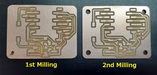
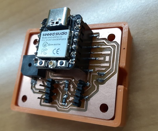
One advantage of this re-make was that it was a good opportunity to work on the unaddressed issue of the past week: Making a case for the board. As described in the last week’s documentation, I had already created holes for all the four courners of the board. I operated the PCB milling machine twice.
Why twice? In the first trial, I tried to cut the outline and holes at one cut. But because the machine started with cutting the outline, once it finished cutting the outline, the board started wobbling and that affected drilling of the holes. So I was forced to stop milling. Also, in the first trial, I forgot to export the outline PNG data with 800 dpi resolution. That also affected the milling result.
I went for the second trial with all the above failures reflected on the way I did PCB milling: 800 dpi resolution, and cutting the outline and holes separately.
Then I proceeded to soldering work. My local session of the day at FabLab Kannai ended when I finished soldering and confirmed the buzzer beat. However, when I went home, I faced with the bad connection again. After the continuity check with a multimeter, I concluded that it was due to insufficient soldering on the buzzer. Since I didn’t have a sodering iron in my house, I went to my office for connection work on the next week day and completed the board development.
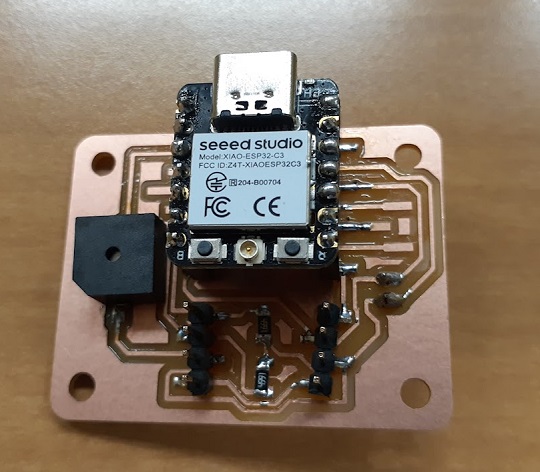
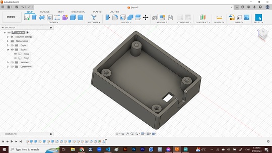
Another issue is the stability of the board. Since I placed the 2-pin battery connector on the bottom side of the wall, the board looked ugly and unstable.
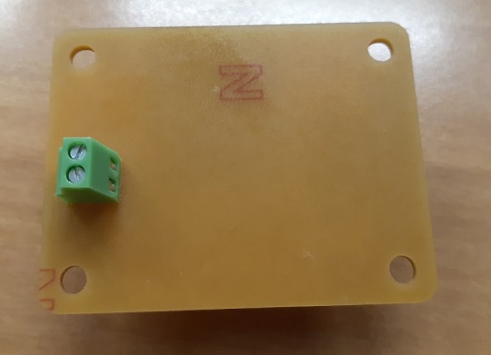
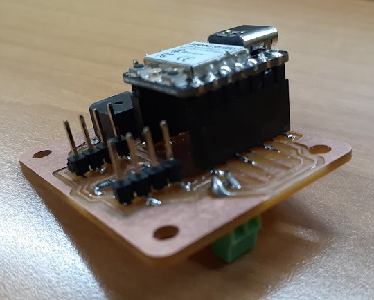
I took the measurement and designed the box with Fusion360. Again I printed twice. First, I misplaced the ditch from which I could put the jump wires into the battery connector. Then, using the mirror function, I reversed the first body and mede the second body for 3D printing.
Device 0: Buzzer
First, I just simply connected the USB cable to the board, and wrote the following simple code to see if I could get the continuous buzzer beat.
const int speakerPin = D0; // the number of the speaker pin

void setup() {
  pinMode(speakerPin, OUTPUT);
  }

void loop() {
  tone(speakerPin, 1000); // When the button is not pressed, keep speaker on with 1000Hz
}
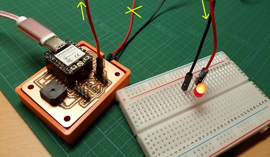
Device 1: LED
Next I tried adding an output device, starting with an simple LED circuit. For this, I assigned the D6 pin for digital output. I placed an red LED and a 220Ω resistor on the bread board, then connected them to the digital output pin and the GND.
| Wire Color | Function | ESP32C3 Pin |
|---|---|---|
| Red | PWM | GPIO21 |
| Black | GND | GND |
Note (Resistor): Resistors act as an impediment to the flow of electricity. The higher the current, the more intense the LED emits light. However, at currents above 20mA, the intensity of LED luminescence does not change much. Even if the current fluctuates, the voltage of the LED does not change much, at around 2V. For normal luminous intensity, a current of a few mA is sufficient. Under these circumstances, the resistance value for current limiting when emitting LEDs at 5mA with a 3.3V power supply is as follows. Since I didn’t have the exact 260Ω resistor at hand, I tried it with a 220Ω resistor.
Resistance = (3.3V - 2V) / 5mA = 260Ω
Power Consumption = 3.3V x 5mA = 16.5mW
The code is very simple. I used the sample LED blink code on the Arduino IDE and specified the GPIO pin for digital outpt.
// the setup function runs once when you press reset or power the board
void setup() {
// initialize digital pin LED_BUILTIN as an output.
   pinMode(21, OUTPUT);
}

// the loop function runs over and over again forever
void loop() {
  digitalWrite(21, HIGH);  // turn the LED on (HIGH is the voltage level)
  delay(1000);             // wait for a second
  digitalWrite(21, LOW);   // turn the LED off by making the voltage LOW
  delay(1000);             // wait for a second
}
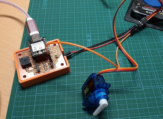
Device 2: Servo
I also tried to connect a servo to my board. I searched for a sample code on the Internet and learned from this site: 趣味的ロボット研究所. It is a project to turn the servo 180 degrees clockwise and after 20 milliseconds to turn 180 degrees backward. This sequence will continue as long as there is power supply.
For this, I made the circuit connection as described in the snapshot below. I appointed GPIO21 as a digital output pin.
| Wire Color | Function | ESP32C3 Pin |
|---|---|---|
| Orange | PWM | GPIO21 |
| Red | Vout | Vout(3.3V) |
| Black | GND | GND |
const int servoPin = 21;
float DutyCycle = 500;

void setup() {
  pinMode(servoPin, OUTPUT);
}

void loop() {
  for (DutyCycle = 500; DutyCycle <= 2400; DutyCycle += 10) {
    digitalWrite(servoPin, HIGH);
    delayMicroseconds(DutyCycle);
    digitalWrite(servoPin, LOW);
    delayMicroseconds(20*1000 - DutyCycle);
  }
  delay(1000);
  for (DutyCycle = 2400; DutyCycle >= 500; DutyCycle -= 10) {
    digitalWrite(servoPin, HIGH);
    delayMicroseconds(DutyCycle);
    digitalWrite(servoPin, LOW);
    delayMicroseconds(20*1000 - DutyCycle);
  }
  delay(1000);
}
Device 3: Solenoid
Finally, until the close of the individual assignment of the week, I also tried a solenoid. The working voltage is different from one type to another. I used the push solenoid of 5V.
One problem I faced when I made the circuit was that my board has no pin for 5V. It only has 3.3V power supply. This forced me to consider adding a transistor to my circuit. For the overall circuit development, I studied it in the following YouTube video: Circuit to safely control a Solenoid with an Arduin.
Note (Transistor): Transistors work to amplify current. In other words, the input current is amplified to the output current. In contrast, field-effect transistors (FET) have the characteristic of controlling the output “current” with the input “voltage”. While the transistor is amplified in proportion to the “current” of the input, in the case of a FET, the amplified current flows to the load in proportion to the “voltage” of the input. I only had N MOSFET (60V25A) at hand and there was no choice but to use the one.
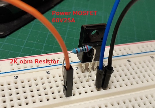
Here is the table for wire connections. As for resistance, I used a 4kΩ resistor without any confidence.
| MOSFET Legs | Wire Color | Connected Pins |
|---|---|---|
| G (Gate) | Orange | GPIO21 (with resistor in between) |
| D (Drain) | Blue | Cathode of Diode Rectifier |
| S (Source) | Black | GND |
Note (Diode Rectifier): A diode is a semiconductor device in general that conducts current in only one direction. Among them, those called “rectifier diodes” are used to convert alternating current (AC) to direct current (DC) by utilizing the fact that current flows only in a certain direction. Also, we have to be aware that the diode has direction. One side of the cylinder-shaped body is wrapped around by a white band. This side is the GND side. Also, I added a 220Ω resistor to the anode of the rectifier diode.
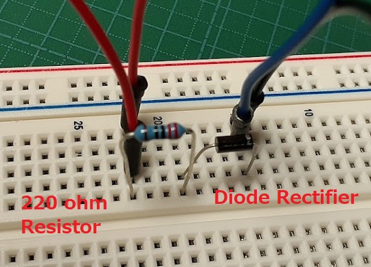
| Diode Electrodes | Wire Color | Connected to |
|---|---|---|
| Anode | Red | Vout |
| Anode | Red | Solenoid |
| Cathode | Blue | MOSFET D |
| Cathode | Black | Solenoid |
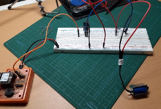
Here is the comprehensive view of the circuit:
Then I proceeded to the programming with Arduino IDE. However, this time I tried to use ChatGPT to get the basic code. Here is the prompt I typed:
I would like to write a program in the Arduino IDE to run a solenoid
push type 5V at 3 second intervals. This will be connected to an ESP32C2.
How should I make the circuit connection and what kind of program should I write?
Then I got the following answer. I changed the GPIO pin assignment to 21.
// Pin assignment for controlling the solenoid
const int solenoidPin = 21;
// Interval set for 3 seconds (3000 milliseconds)
const unsigned long interval = 3000;

// Variables to keep track of time and solenoid state
unsigned long previousMillis = 0;  // Variable to store the last time the solenoid was toggled
bool solenoidState = false;  // Variable to store the current state of the solenoid (on or off)

void setup() {
  // Set the solenoid pin as an OUTPUT
  pinMode(solenoidPin, OUTPUT);
}

void loop() {
  // Capture the current time
  unsigned long currentMillis = millis();

  // Check if the time since the last toggle is greater than or equal to the interval
  if (currentMillis - previousMillis >= interval) {
    // Update the last toggle time to the current time
    previousMillis = currentMillis;

    // Toggle the solenoid state
    solenoidState = !solenoidState;

    // Control the solenoid according to the toggled state
    digitalWrite(solenoidPin, solenoidState ? HIGH : LOW);
  }
}
You can see the result in the following videoclip. However, I have to confess that I was not sure about my resistor choice.