13. Networking and Communications
Weekly Digest (Thu. April 25 to Wed. May 1)
| Date | Time | Place | Activities |
|---|---|---|---|
| Thu. April 25 | 11:30-20:00 | FabLab Kannai | Follow-up on Week11 and 12 |
| Fri. April 26 | 11:00-14:00 | Home | Documentation on Week12 |
| 15:00-18:30 | Akihabara | (Final Project) Shopping Electronics Parts | |
| Sat. April 27 | 10:00-18:00 | FabLab Kannai | Local Session on Week13 |
| 21:00-01:00 | Home | Follow-up on Week11 (Distance Sensor x Arduino IDE) and Documentation | |
| Sun. April 28 | 8:00-10:30 13:00-14:00 |
Home | Documentation on Week13 |
| Mon. April 29 | 9:00-17:00 20:00-23:00 |
Home | Documentation on Week13, (Final Project) BLE Connection Test and Documentation, Recitation |
| Tue. April 30 | 16:00-20:00 21:00-23:00 |
Home | (Final Project) BLE Connection Test and Documentation, Asian Review |
| Wed. May 1 | 9:00-18:00 | Home | (Final Project) BLE Connection Test, Research on Buzzer Setting |
Individual Assignments Overview
Here is the list of individual assignments given by the instructors. As for the Group Assignment, please see the Group Assignment page on the FabLab Kannai website:
  Design, build, and connect wired or wireless node(s) with network or bus addresses
  and local input &/or output device(s)
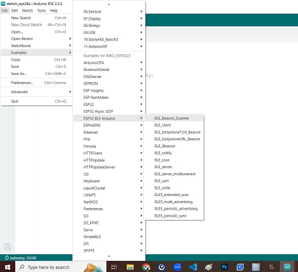
1. Familiarization to Bluetooth Low Energy (BLE)
While I was browsing the Internet, I have found the webpage Seeed Studio XIAO ESP32C3でBLE ② BLEのサンプルを動かす that shares the owner’s experience in running sketches for Xiao ESP32C3 using the Arduino IDE. Instead of the ArduinoBLE library, he uses ESP32’s BLE library.
In BLE, the device that transmits data, such as sensor readings, is called the peripheral, and the device that connects to the transmitter to receive data is called the central. The peripheral performs an advertising action to attract centrals to connect. The central performs a scanning action to discover devices that are advertising.
In this website, the owner tried to upload two sample sketches from the ESP32 BLE Arduino Library: “BLE_scan” and “BLE_uart”.
1-1. BLE_scan
The BLE_scan is the code for the Xiao ESP32C3 board to scan the active BLE transmitters. We could just open the sample sketch and upload it.
/*
   Based on Neil Kolban example for IDF: https://github.com/nkolban/esp32-snippets/blob/master/cpp_utils/tests/BLE%20Tests/SampleScan.cpp
   Ported to Arduino ESP32 by Evandro Copercini
*/

#include <BLEDevice.h>
#include <BLEUtils.h>
#include <BLEScan.h>
#include <BLEAdvertisedDevice.h>

int scanTime = 5; //In seconds
BLEScan* pBLEScan;

class MyAdvertisedDeviceCallbacks: public BLEAdvertisedDeviceCallbacks {
    void onResult(BLEAdvertisedDevice advertisedDevice) {
      Serial.printf("Advertised Device: %s \n", advertisedDevice.toString().c_str());
    }
};

void setup() {
  Serial.begin(115200);
  Serial.println("Scanning...");

  BLEDevice::init("");
  pBLEScan = BLEDevice::getScan(); //create new scan
  pBLEScan->setAdvertisedDeviceCallbacks(new MyAdvertisedDeviceCallbacks());
  pBLEScan->setActiveScan(true); //active scan uses more power, but get results faster
  pBLEScan->setInterval(100);
  pBLEScan->setWindow(99);  // less or equal setInterval value
}

void loop() {
  // put your main code here, to run repeatedly:
  BLEScanResults foundDevices = pBLEScan->start(scanTime, false);
  Serial.print("Devices found: ");
  Serial.println(foundDevices.getCount());
  Serial.println("Scan done!");
  pBLEScan->clearResults();   // delete results fromBLEScan buffer to release memory
  delay(2000);
}
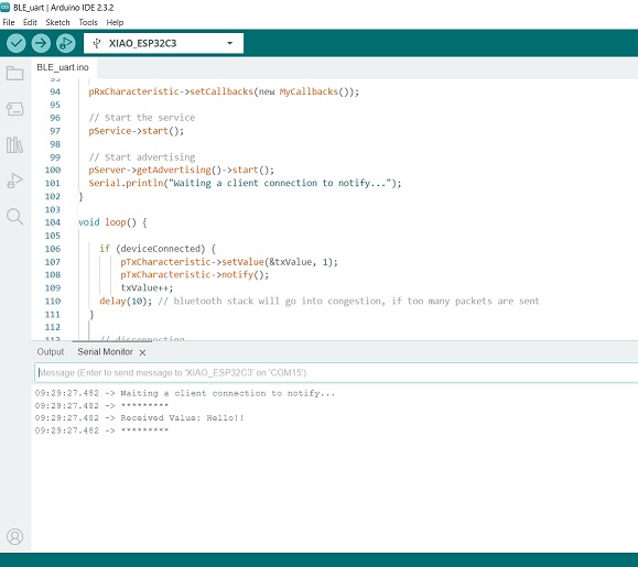
1-2. BLE_uart
The BLE_uart is the code that makes the Xiao ESP32C3 board a BLE server that sends notifications once it receives them. We could just open the sample sketch and upload it. But this time, I changed the BLE device name to “KojiESP32” and ran it.
/*
    Video: https://www.youtube.com/watch?v=oCMOYS71NIU
    Based on Neil Kolban example for IDF: https://github.com/nkolban/esp32-snippets/blob/master/cpp_utils/tests/BLE%20Tests/SampleNotify.cpp
    Ported to Arduino ESP32 by Evandro Copercini

   Create a BLE server that, once we receive a connection, will send periodic notifications.
   The service advertises itself as: 6E400001-B5A3-F393-E0A9-E50E24DCCA9E
   Has a characteristic of: 6E400002-B5A3-F393-E0A9-E50E24DCCA9E - used for receiving data with "WRITE"
   Has a characteristic of: 6E400003-B5A3-F393-E0A9-E50E24DCCA9E - used to send data with  "NOTIFY"

   The design of creating the BLE server is:
   1. Create a BLE Server
   2. Create a BLE Service
   3. Create a BLE Characteristic on the Service
   4. Create a BLE Descriptor on the characteristic
   5. Start the service.
   6. Start advertising.

   In this example rxValue is the data received (only accessible inside that function).
   And txValue is the data to be sent, in this example just a byte incremented every second.
*/
#include <BLEDevice.h>
#include <BLEServer.h>
#include <BLEUtils.h>
#include <BLE2902.h>

BLEServer *pServer = NULL;
BLECharacteristic * pTxCharacteristic;
bool deviceConnected = false;
bool oldDeviceConnected = false;
uint8_t txValue = 0;

// See the following for generating UUIDs:
// https://www.uuidgenerator.net/

#define SERVICE_UUID           "6E400001-B5A3-F393-E0A9-E50E24DCCA9E" // UART service UUID
#define CHARACTERISTIC_UUID_RX "6E400002-B5A3-F393-E0A9-E50E24DCCA9E"
#define CHARACTERISTIC_UUID_TX "6E400003-B5A3-F393-E0A9-E50E24DCCA9E"


class MyServerCallbacks: public BLEServerCallbacks {
    void onConnect(BLEServer* pServer) {
      deviceConnected = true;
    };

    void onDisconnect(BLEServer* pServer) {
      deviceConnected = false;
    }
};

class MyCallbacks: public BLECharacteristicCallbacks {
    void onWrite(BLECharacteristic *pCharacteristic) {
      std::string rxValue = pCharacteristic->getValue();

      if (rxValue.length() > 0) {
        Serial.println("*********");
        Serial.print("Received Value: ");
        for (int i = 0; i < rxValue.length(); i++)
          Serial.print(rxValue[i]);

        Serial.println();
        Serial.println("*********");
      }
    }
};


void setup() {
  Serial.begin(115200);

  // Create the BLE Device
  BLEDevice::init("KojiESP32");

  // Create the BLE Server
  pServer = BLEDevice::createServer();
  pServer->setCallbacks(new MyServerCallbacks());

  // Create the BLE Service
  BLEService *pService = pServer->createService(SERVICE_UUID);

  // Create a BLE Characteristic
  pTxCharacteristic = pService->createCharacteristic(
                                        CHARACTERISTIC_UUID_TX,
                                        BLECharacteristic::PROPERTY_NOTIFY
                                    );

  pTxCharacteristic->addDescriptor(new BLE2902());

  BLECharacteristic * pRxCharacteristic = pService->createCharacteristic(
                                             CHARACTERISTIC_UUID_RX,
                                            BLECharacteristic::PROPERTY_WRITE
                                        );

  pRxCharacteristic->setCallbacks(new MyCallbacks());

  // Start the service
  pService->start();

  // Start advertising
  pServer->getAdvertising()->start();
  Serial.println("Waiting a client connection to notify...");
}

void loop() {

    if (deviceConnected) {
        pTxCharacteristic->setValue(&txValue, 1);
        pTxCharacteristic->notify();
        txValue++;
        delay(10); // bluetooth stack will go into congestion, if too many packets are sent
    }

    // disconnecting
    if (!deviceConnected && oldDeviceConnected) {
        delay(500); // give the bluetooth stack the chance to get things ready
        pServer->startAdvertising(); // restart advertising
        Serial.println("start advertising");
        oldDeviceConnected = deviceConnected;
    }
    // connecting
    if (deviceConnected && !oldDeviceConnected) {
        // do stuff here on connecting
        oldDeviceConnected = deviceConnected;
    }
}
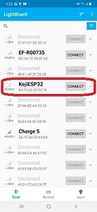
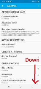
Once installed, I tapped the LightBlue app and searched for my BLE “KojiESP32”. I found it and tapped “Connect” to the Advertisement Data page.
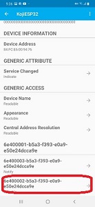
Then I scrolled down the page and tapped my UUID to proceed. There are two options: “Notify” and “Writable”. If you tap “Notify”, you could receive the serial data sent by the Xiao board. If you tap “Writable”, you could send a message to the board.
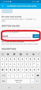
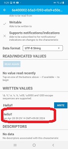
This time I tapped “Writable”. After switching the data format to “UTF 8-string”, I typed “Hello!!” in the blank box under the “WRITTEN VALUES” headline and typed “Write”. Then I could see the texts both on my mobile app and the Arduino IDE serial monitor.
2. Wireless Connection of Input Devices
2-1. Setup of the Temperature Sensor: MCP9808
The owner of the above website further tried to transmit the air pressure data via BLE Seeed Studio XIAO ESP32C3でBLE ③ I2CでセンサBMP280をつなぐ with BMP280 temperature and air pressure sensor. However, I didn’t have the same sensor with me and then decided to test the data transmission with another temperature sensor, Adafruit MCP9808, instead.
Here is the summary of the wire connection.
| ESP32C3 | MCP9808 Breakout Board |
|---|---|
| 3V3 | VIN |
| GND | GND |
| SDA | SDA |
| SCL | SCL |
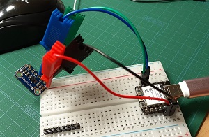
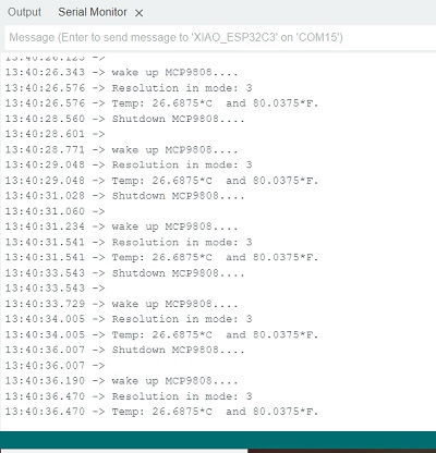
Then I called the sample sketch “mcp9808test” from the Arduino IDE Library and uploaded.
/**************************************************************************/
/*!
This is a demo for the Adafruit MCP9808 breakout
----> http://www.adafruit.com/products/1782
Adafruit invests time and resources providing this open source code,
please support Adafruit and open-source hardware by purchasing
products from Adafruit!
*/
/**************************************************************************/

#include <Wire.h>
#include "Adafruit_MCP9808.h"

// Create the MCP9808 temperature sensor object
Adafruit_MCP9808 tempsensor = Adafruit_MCP9808();

void setup() {
  Serial.begin(9600);
  while (!Serial); //waits for serial terminal to be open, necessary in newer arduino boards.
  Serial.println("MCP9808 demo");

  // Make sure the sensor is found, you can also pass in a different i2c
  // address with tempsensor.begin(0x19) for example, also can be left in blank for default address use
  // Also there is a table with all addres possible for this sensor, you can connect multiple sensors
  // to the same i2c bus, just configure each sensor with a different address and define multiple objects for that
  //  A2 A1 A0 address
  //  0  0  0   0x18  this is the default address
  //  0  0  1   0x19
  //  0  1  0   0x1A
  //  0  1  1   0x1B
  //  1  0  0   0x1C
  //  1  0  1   0x1D
  //  1  1  0   0x1E
  //  1  1  1   0x1F
  if (!tempsensor.begin(0x18)) {
    Serial.println("Couldn't find MCP9808! Check your connections and verify the address is correct.");
    while (1);
  }

   Serial.println("Found MCP9808!");

  tempsensor.setResolution(3); // sets the resolution mode of reading, the modes are defined in the table bellow:
  // Mode Resolution SampleTime
  //  0    0.5°C       30 ms
  //  1    0.25°C      65 ms
  //  2    0.125°C     130 ms
  //  3    0.0625°C    250 ms
}

void loop() {
  Serial.println("wake up MCP9808.... "); // wake up MCP9808 - power consumption ~200 mikro Ampere
  tempsensor.wake();   // wake up, ready to read!

  // Read and print out the temperature, also shows the resolution mode used for reading.
  Serial.print("Resolution in mode: ");
  Serial.println (tempsensor.getResolution());
  float c = tempsensor.readTempC();
  float f = tempsensor.readTempF();
  Serial.print("Temp: ");
  Serial.print(c, 4); Serial.print("*C\t and ");
  Serial.print(f, 4); Serial.println("*F.");

  delay(2000);
  Serial.println("Shutdown MCP9808.... ");
  tempsensor.shutdown_wake(1); // shutdown MSP9808 - power consumption ~0.1 mikro Ampere, stops temperature sampling
  Serial.println("");
  delay(200);
}
2-2. Transmitting the Temperature Data to Mobile Phone
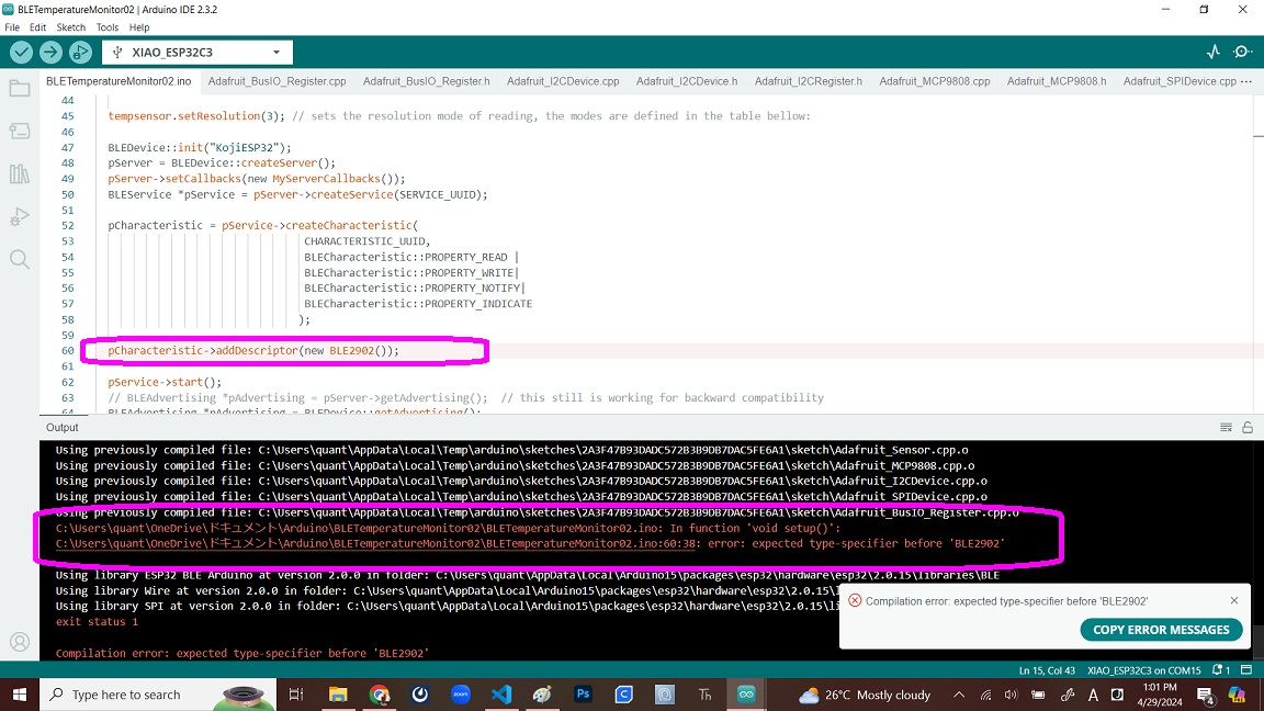
Now that I confirmed the code for getting the serial data from the input device, the next step is to make ESP32C3 a server to send the serial data to my mobile phone via BLE. As of afternoon, Monday, April 29, I have not been successful in setting up the Bluetooth connection between the ESP32C3 board and my mobile phone so that I could receive the temperature data with my mobile. I have faced a series of compiling errors and have been stacked by the last one. Therefore, as temproary measure, I hereby document what happened to my exercise.
I opened the sample sketch “BLE_notify” from the “ESP32 BLE Arduino” Library and uploaded successfully.
/*
    Video: https://www.youtube.com/watch?v=oCMOYS71NIU
    Based on Neil Kolban example for IDF: https://github.com/nkolban/esp32-snippets/blob/master/cpp_utils/tests/BLE%20Tests/SampleNotify.cpp
    Ported to Arduino ESP32 by Evandro Copercini
    updated by chegewara

   Create a BLE server that, once we receive a connection, will send periodic notifications.
   The service advertises itself as: 4fafc201-1fb5-459e-8fcc-c5c9c331914b
   And has a characteristic of: beb5483e-36e1-4688-b7f5-ea07361b26a8

   The design of creating the BLE server is:
   1. Create a BLE Server
   2. Create a BLE Service
   3. Create a BLE Characteristic on the Service
   4. Create a BLE Descriptor on the characteristic
   5. Start the service.
   6. Start advertising.

   A connect hander associated with the server starts a background task that performs notification
   every couple of seconds.
*/
#include <BLEDevice.h>
#include <BLEServer.h>
#include <BLEUtils.h>
#include <BLE2902.h>

BLEServer* pServer = NULL;
BLECharacteristic* pCharacteristic = NULL;
bool deviceConnected = false;
bool oldDeviceConnected = false;
uint32_t value = 0;

// See the following for generating UUIDs:
// https://www.uuidgenerator.net/

#define SERVICE_UUID        "4fafc201-1fb5-459e-8fcc-c5c9c331914b"
#define CHARACTERISTIC_UUID "beb5483e-36e1-4688-b7f5-ea07361b26a8"


class MyServerCallbacks: public BLEServerCallbacks {
    void onConnect(BLEServer* pServer) {
      deviceConnected = true;
    };

    void onDisconnect(BLEServer* pServer) {
      deviceConnected = false;
    }
};


void setup() {
  Serial.begin(115200);

  // Create the BLE Device
  BLEDevice::init("ESP32");

  // Create the BLE Server
  pServer = BLEDevice::createServer();
  pServer->setCallbacks(new MyServerCallbacks());

  // Create the BLE Service
  BLEService *pService = pServer->createService(SERVICE_UUID);

  // Create a BLE Characteristic
  pCharacteristic = pService->createCharacteristic(
                      CHARACTERISTIC_UUID,
                      BLECharacteristic::PROPERTY_READ   |
                      BLECharacteristic::PROPERTY_WRITE  |
                      BLECharacteristic::PROPERTY_NOTIFY |
                      BLECharacteristic::PROPERTY_INDICATE
                    );

  // https://www.bluetooth.com/specifications/gatt/viewer?attributeXmlFile=org.bluetooth.descriptor.gatt.client_characteristic_configuration.xml
  // Create a BLE Descriptor
  pCharacteristic->addDescriptor(new BLE2902());

  // Start the service
  pService->start();

  // Start advertising
  BLEAdvertising *pAdvertising = BLEDevice::getAdvertising();
  pAdvertising->addServiceUUID(SERVICE_UUID);
  pAdvertising->setScanResponse(false);
  pAdvertising->setMinPreferred(0x0);  // set value to 0x00 to not advertise this parameter
  BLEDevice::startAdvertising();
  Serial.println("Waiting a client connection to notify...");
}

void loop() {
    // notify changed value
    if (deviceConnected) {
        pCharacteristic->setValue((uint8_t*)&value, 4);
        pCharacteristic->notify();
        value++;
        delay(3); // bluetooth stack will go into congestion, if too many packets are sent, in 6 hours test i was able to go as low as 3ms
    }
    // disconnecting
    if (!deviceConnected && oldDeviceConnected) {
        delay(500); // give the bluetooth stack the chance to get things ready
        pServer->startAdvertising(); // restart advertising
        Serial.println("start advertising");
        oldDeviceConnected = deviceConnected;
    }
    // connecting
    if (deviceConnected && !oldDeviceConnected) {
        // do stuff here on connecting
        oldDeviceConnected = deviceConnected;
    }
}
#include <BLEDevice.h>
#include <BLEUtils.h>
#include <BLEServer.h>
#include "BLE2902.h"
#include <Wire.h>
#include "Adafruit_Sensor.h"
#include "Adafruit_MCP9808.h"

// Create the MCP9808 temperature sensor object
Adafruit_MCP9808 tempsensor = Adafruit_MCP9808();

float temp = 0;

BLEServer* pServer = NULL;
BLECharacteristic* pCharacteristic = NULL;
bool deviceConnected = false;
bool oldDeviceConnected = false;
uint32_t value = 0;

#define SERVICE_UUID        "4fafc201-1fb5-459e-8fcc-c5c9c331914b"
#define CHARACTERISTIC_UUID "beb5483e-36e1-4688-b7f5-ea07361b26a8"

class MyServerCallbacks: public BLEServerCallbacks {
    void onConnect(BLEServer* pServer) {
      deviceConnected = true;
    };

    void onDisconnect(BLEServer* pServer) {
      deviceConnected = false;
    }
};

void setup() {
  Serial.begin(115200);
  while (!Serial); //waits for serial terminal to be open, necessary in newer arduino boards.
  Serial.println("MCP9808 demo");

  if (!tempsensor.begin(0x18)) {
    Serial.println("Couldn't find MCP9808! Check your connections and verify the address is correct.");
    while (1);
  }

   Serial.println("Found MCP9808!");

  tempsensor.setResolution(3); // sets the resolution mode of reading, the modes are defined in the table bellow:

  BLEDevice::init("KojiESP32");
  pServer = BLEDevice::createServer();
  pServer->setCallbacks(new MyServerCallbacks());
  BLEService *pService = pServer->createService(SERVICE_UUID);

  pCharacteristic = pService->createCharacteristic(
                                 CHARACTERISTIC_UUID,
                                 BLECharacteristic::PROPERTY_READ |
                                 BLECharacteristic::PROPERTY_WRITE|
                                 BLECharacteristic::PROPERTY_NOTIFY|
                                 BLECharacteristic::PROPERTY_INDICATE
                                );

  pCharacteristic->addDescriptor(new BLE2902());

  pService->start();
  // BLEAdvertising *pAdvertising = pServer->getAdvertising();  // this still is working for backward compatibility
  BLEAdvertising *pAdvertising = BLEDevice::getAdvertising();
  pAdvertising->addServiceUUID(SERVICE_UUID);
  pAdvertising->setScanResponse(false);
  pAdvertising->setMinPreferred(0x0);
  BLEDevice::startAdvertising();
  Serial.println("Waiting a client connection to notify...");

}

void loop() {
   // notify changed value
  if (deviceConnected) {
    pCharacteristic->setValue((uint8_t*)&value, 4);
    pCharacteristic->notify();
    value++;
    delay(3); // bluetooth stack will go into congestion, if too many packets are sent, in 6 hours test i was able to go as low as 3ms
  }
  // disconnecting
  if (!deviceConnected && oldDeviceConnected) {
    delay(500); // give the bluetooth stack the chance to get things ready
    pServer->startAdvertising(); // restart advertising
    Serial.println("start advertising");
    oldDeviceConnected = deviceConnected;
  }
  // connecting
  if (deviceConnected && !oldDeviceConnected) {
      // do stuff here on connecting
    oldDeviceConnected = deviceConnected;
  }
}
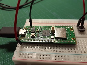
3. Alternative Scenario with Raspberry Pi PicoW
With the possibility of using Raspberry Pi PicoW (hereinafter referred to as “RPi PicoW” or “PicoW” as a board for my final project, I also tried to replicate the same serial communication with PicoW via Thonny IDE. I browsed the Internet and searched for the way to set up the BLE connection. For the exercieses I did for the documentation of this section, I mainly followed the steps described in the following website Pi Pico W でBluetooth Low Energy(BLE)を試してみる.
As a matter of course, the first step described in the above reference site was about the installing of the MicroPython UF2 file Raspberry Pi Documentation to the device.
3-1. Preparation for Wireless Connection via BLE
I learned that for setting up the BLE connection we should create the following three files and save them in the RPi PicoW device.
ble_advertising.py
# Helpers for generating BLE advertising payloads.

from micropython import const
import struct
import bluetooth

# Advertising payloads are repeated packets of the following form:
#   1 byte data length (N + 1)
#   1 byte type (see constants below)
#   N bytes type-specific data

_ADV_TYPE_FLAGS = const(0x01)
_ADV_TYPE_NAME = const(0x09)
_ADV_TYPE_UUID16_COMPLETE = const(0x3)
_ADV_TYPE_UUID32_COMPLETE = const(0x5)
_ADV_TYPE_UUID128_COMPLETE = const(0x7)
_ADV_TYPE_UUID16_MORE = const(0x2)
_ADV_TYPE_UUID32_MORE = const(0x4)
_ADV_TYPE_UUID128_MORE = const(0x6)
_ADV_TYPE_APPEARANCE = const(0x19)


# Generate a payload to be passed to gap_advertise(adv_data=...).
def advertising_payload(limited_disc=False, br_edr=False, name=None, services=None, appearance=0):
    payload = bytearray()

    def _append(adv_type, value):
        nonlocal payload
        payload += struct.pack("BB", len(value) + 1, adv_type) + value

    _append(
        _ADV_TYPE_FLAGS,
        struct.pack("B", (0x01 if limited_disc else 0x02) + (0x18 if br_edr else 0x04)),
    )

    if name:
        _append(_ADV_TYPE_NAME, name)

    if services:
        for uuid in services:
            b = bytes(uuid)
            if len(b) == 2:
                _append(_ADV_TYPE_UUID16_COMPLETE, b)
            elif len(b) == 4:
                _append(_ADV_TYPE_UUID32_COMPLETE, b)
            elif len(b) == 16:
                _append(_ADV_TYPE_UUID128_COMPLETE, b)

    # See org.bluetooth.characteristic.gap.appearance.xml
    if appearance:
        _append(_ADV_TYPE_APPEARANCE, struct.pack("<h", appearance))

    return payload


def decode_field(payload, adv_type):
    i = 0
    result = []
    while i + 1 < len(payload):
        if payload[i + 1] == adv_type:
            result.append(payload[i + 2 : i + payload[i] + 1])
        i += 1 + payload[i]
    return result


def decode_name(payload):
    n = decode_field(payload, _ADV_TYPE_NAME)
    return str(n[0], "utf-8") if n else ""


def decode_services(payload):
    services = []
    for u in decode_field(payload, _ADV_TYPE_UUID16_COMPLETE):
        services.append(bluetooth.UUID(struct.unpack("<h", u)[0]))
    for u in decode_field(payload, _ADV_TYPE_UUID32_COMPLETE):
        services.append(bluetooth.UUID(struct.unpack("<d", u)[0]))
    for u in decode_field(payload, _ADV_TYPE_UUID128_COMPLETE):
        services.append(bluetooth.UUID(u))
    return services


def demo():
    payload = advertising_payload(
        name="micropython",
        services=[bluetooth.UUID(0x181A), bluetooth.UUID("6E400001-B5A3-F393-E0A9-E50E24DCCA9E")],
    )
    print(payload)
    print(decode_name(payload))
    print(decode_services(payload))


if __name__ == "__main__":
    demo()
ble_simple_peripheral.py
# This example demonstrates a UART periperhal.

import bluetooth
import random
import struct
import time
from ble_advertising import advertising_payload

from micropython import const

_IRQ_CENTRAL_CONNECT = const(1)
_IRQ_CENTRAL_DISCONNECT = const(2)
_IRQ_GATTS_WRITE = const(3)

_FLAG_READ = const(0x0002)
_FLAG_WRITE_NO_RESPONSE = const(0x0004)
_FLAG_WRITE = const(0x0008)
_FLAG_NOTIFY = const(0x0010)

_UART_UUID = bluetooth.UUID("6E400001-B5A3-F393-E0A9-E50E24DCCA9E")
_UART_TX = (
    bluetooth.UUID("6E400003-B5A3-F393-E0A9-E50E24DCCA9E"),
    _FLAG_READ | _FLAG_NOTIFY,
)
_UART_RX = (
    bluetooth.UUID("6E400002-B5A3-F393-E0A9-E50E24DCCA9E"),
    _FLAG_WRITE | _FLAG_WRITE_NO_RESPONSE,
)
_UART_SERVICE = (
    _UART_UUID,
    (_UART_TX, _UART_RX),
)


class BLESimplePeripheral:
    def __init__(self, ble, name="mpy-uart"):
        self._ble = ble
        self._ble.active(True)
        self._ble.irq(self._irq)
        ((self._handle_tx, self._handle_rx),) = self._ble.gatts_register_services((_UART_SERVICE,))
        self._connections = set()
        self._write_callback = None
        self._payload = advertising_payload(name=name, services=[_UART_UUID])
        self._advertise()

    def _irq(self, event, data):
        # Track connections so we can send notifications.
        if event == _IRQ_CENTRAL_CONNECT:
            conn_handle, _, _ = data
            print("New connection", conn_handle)
            self._connections.add(conn_handle)
        elif event == _IRQ_CENTRAL_DISCONNECT:
            conn_handle, _, _ = data
            print("Disconnected", conn_handle)
            self._connections.remove(conn_handle)
            # Start advertising again to allow a new connection.
            self._advertise()
        elif event == _IRQ_GATTS_WRITE:
            conn_handle, value_handle = data
            value = self._ble.gatts_read(value_handle)
            if value_handle == self._handle_rx and self._write_callback:
                self._write_callback(value)

    def send(self, data):
        for conn_handle in self._connections:
            self._ble.gatts_notify(conn_handle, self._handle_tx, data)

    def is_connected(self):
        return len(self._connections) > 0

    def _advertise(self, interval_us=500000):
        print("Starting advertising")
        self._ble.gap_advertise(interval_us, adv_data=self._payload)

    def on_write(self, callback):
        self._write_callback = callback


def demo():
    ble = bluetooth.BLE()
    p = BLESimplePeripheral(ble)

    def on_rx(v):
        print("RX", v)

    p.on_write(on_rx)

    i = 0
    while True:
        if p.is_connected():
            # Short burst of queued notifications.
            for _ in range(3):
                data = str(i) + "_"
                print("TX", data)
                p.send(data)
                i += 1
        time.sleep_ms(100)


if __name__ == "__main__":
    demo()
main.py
Now in the main file, I prepared the code to record the button push on the mobile app, LightBlue. For this, I prepared the simple wire connection between the PicoW board and the toggle switch.
# Import necessary modules
from machine import Pin
import bluetooth
from ble_simple_peripheral import BLESimplePeripheral
import time

# Create a Bluetooth Low Energy (BLE) object
ble = bluetooth.BLE()
# Create an instance of the BLESimplePeripheral class with the BLE object
sp = BLESimplePeripheral(ble)

# Set the debounce time to 0. Used for switch debouncing
debounce_time=0

# Create a Pin object for Pin 0, configure it as an input with a pull-up resistor
pin = Pin(0, Pin.IN, Pin.PULL_UP)

while True:
    # Check if the pin value is 0 and if debounce time has elapsed (more than 300 milliseconds)
    if ((pin.value() is 0) and (time.ticks_ms()-debounce_time) > 300):
        # Check if the BLE connection is established
        if sp.is_connected():
            # Create a message string
            msg="pushbutton pressed\n"
            # Send the message via BLE
            sp.send(msg)
        # Update the debounce time
        debounce_time=time.ticks_ms()
Wireless Connection
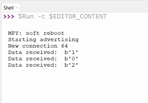
With the above three files onboard, I ran the program and immediately the python shell showed that the the board started advertising.
Next I took up my mobile phone and opened the LightBlue app. Soon I could find the “MPR-URT” signal.
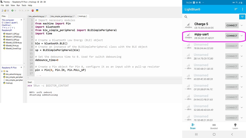
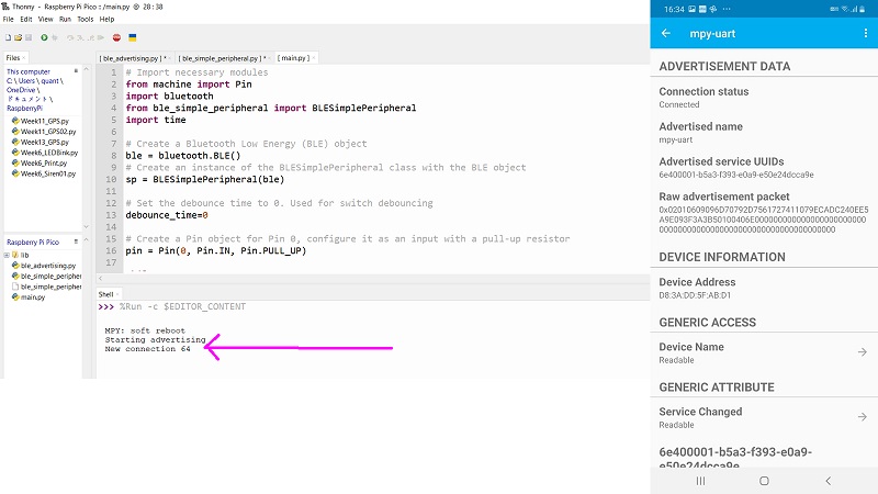
Once I tapped “Connect”, then the mobile page automatically changed to the profile of the MPR-URT, and at the same time, I could see a new message in the python shell as well.
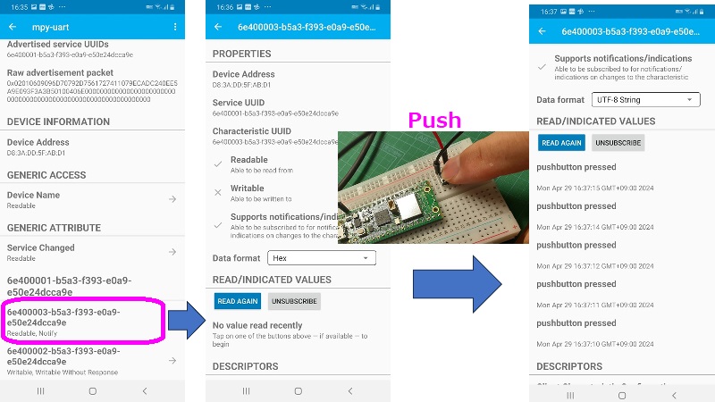
Then I pressed the toggle button a few times on the peripheral side. This was recorded on the central side and I could see at what time the button was pressed.
3-2. Monitoring of the Built-in Temperature Sensor of the Board
Based on the above connection setting, I tried to collect the temperature data of the board with the built-in sensor.
I used the sample sketches from raspberrypi/pico-micropython-examples. There were three py files to download and I opened all of them on the Thonny IDE: ble_advertising.py / picow_ble_temp_reader.py / picow_ble_temp_sensor.py. Due to the length of my weekly assignment page, I will skip posting the whole codes herewith.
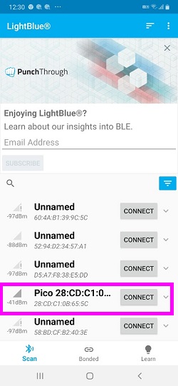
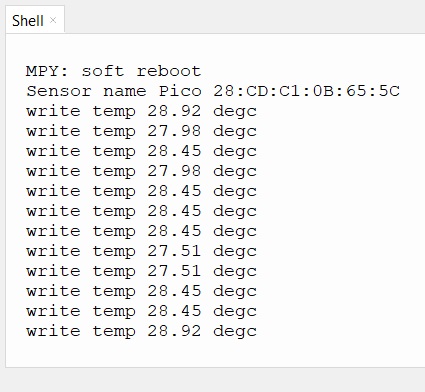
Once I started running the program, the python shell started listing the temperature data the sensor collected periodically. Also, I could see that the periphery name and its MAC address were indicated in the python shell, too.
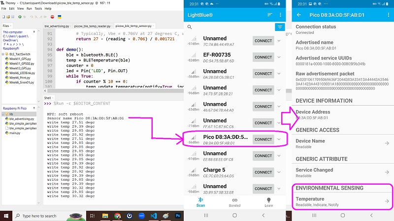
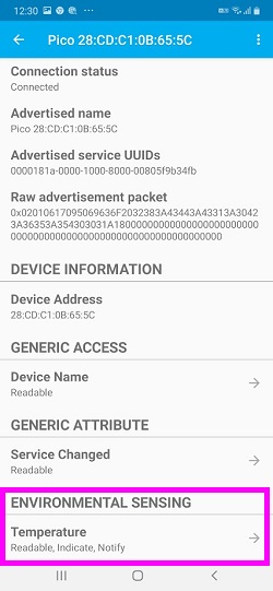
I took my mobile phone and opened the LightBlue app. I could find the periphery name and its MAc address easily. I tapped “Connect” and opened the profile of the periphery. Down in the profile, I found the sub-title headline “ENVIRONMENTAL SENSING” and the “Temperature” was ready for tapping. When I tapped “Temperature”, I moved to the Temperature page and saw the serial data keep coming into the center.
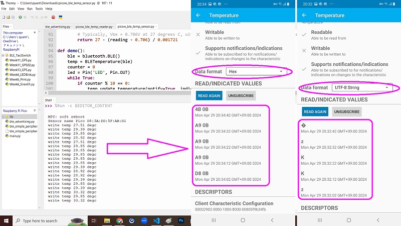
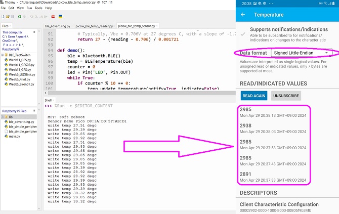
However, default data format “Hex” was not suitable to show serial temperature data. After trying a few different format options, I finally found that “Signed Little-Endian” could be the best data format for temperature, but still it was 100 times larger than the actual degrees Celsius.
Updates on June 21, 2024
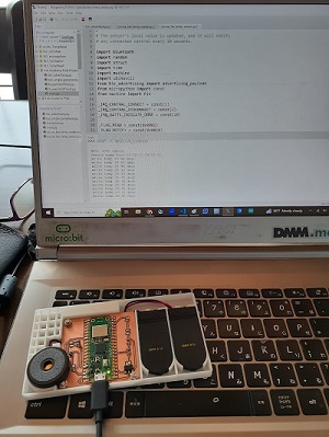
As pointed out by our Instructor, who said that I should replicate this with the board I developed, I once tried to test it with my board. Here is the result.
I simply uploaded the three files I mentioned in the 3-2 above. Here is the result photo and video.
Also, you could see how the temp data on the central and peripheral devices were recorded. First, please see the steps I took to start reading the temperature with the LightBlue app on my mobile. Then please see how it was recorded on the python shell of the Thonny IDE.

With this, I feel that I could meet all the requirements for the Individual Assignment for Week13. But there still remain the following problems:
-
When I scanned for I2C address for the MCP9808 sensor with Thonny IDE and PicoW board, I saw there were too many I2C addresses. This made it difficult to identify the I2C address for the sensor. This happened even though the MCP9808 was the only sensor connected to my PicoW board.
-
I came up with an assumption that the MCP9808 sensor was damaged, and tried to flash the same codes I used in 2-1 and 2-2 above with Arduino IDE and Xiao ESP32C3 board. I saw the message that the program was not able to detect the MCP9808 sensor. I tried the same with another laptop and faced the same result. I concluded that there was something wrong with the sensor.
In order to continue to work with MCP9808 temperature sensor, I need to wait until I get a new sensor I ordered on the e-commerce platform.
3-3. Switching On/Off LED
Then as a warm-up exercise for my final project, I tried to set up a communication for the central side to control the peripheral side. The first step would be to turn on/off the LED connected to the Pico W board.
I expected that I could use the same files: “ble_advertising.py” and “ble_simple_peripheral.py”. I thought that the only thing I should do is to prepare the main code for LED blinking and communication with the central in terms of the “main.py” file.
There were a few predecesors who have already tried this and shared their experience online. Many of them tried to turn on/off the onboard LED of the PicoW. Therefore, I assigned another Pin for output and added an LED circuit on the breadboard.
Also, I wanted to assign two different messages, say “1” and “0” to turn on and off the LED respectively.
The following is the code I wrote and tried for test run:
# Import necessary modules
from machine import Pin
import bluetooth
from ble_simple_peripheral import BLESimplePeripheral

# Create a Bluetooth Low Energy (BLE) object
ble = bluetooth.BLE()

# Create an instance of the BLESimplePeripheral class with the BLE object
sp = BLESimplePeripheral(ble)

# Create a Pin object for the LED, configure it as an output
led = Pin( 15, Pin.OUT)

# Initialize the LED state to 0 (off)
led.off()

# Define a callback function to handle received data
def on_rx(data):
    print("Data received: ", data)  # Print the received data
    if data == b'1\r\n':  # Check if the received data is "1"
        led.on()          # LED on
        sp.send("LED ON\n")  # Send a confirmation message
    elif data == b'0\r\n':  # Check if the received data is "0"
        led.off()           # LED off
        sp.send("LED OFF\n")  # Send a confirmation message
    else:  # Check if the received data is other than 0 or 1
        sp.send("Do Nothing\n")  # Send a confirmation message

# Start an infinite loop
while True:
    if sp.is_connected():  # Check if a BLE connection is established
        sp.on_write(on_rx)  # Set the callback function for data reception
Unfortunately, as of the evening of Tuesday, April 30, it’s never been successful. It’s connected to my Android phone via BLE. But nothing happened to the LED. Also, my Android app and the python shell on my laptop only showed the messages (1, 0, other numbers/texts) I wrote from the central, but didn’t show the messages that the peripheral sent back to the central.
Updates on June 21, 2024
I left the Week13 Individual Assignment without rectifying this problem. It was not a good idea to document what went wrong without writing about what I did to solve it. Therefore, before the closure of the local evaluation, I took time to write what I did for this issue.
Test1 Toggle Switch:I started with the toggle-switching to turn on/off the on-board LED and the buzzer. In fact, I did succeed on this earlier as the first step to reach the final code for my Final Project. Please see the Final Projet - Bluetooth Connection.
This is the code I modified for toggling LED on and off. I also added a few lines to switch on/off the buzzer together with the on-board LED.
    # Import necessary modules
    from machine import Pin
    import bluetooth
    from ble_simple_peripheral import BLESimplePeripheral

    # Create a Bluetooth Low Energy (BLE) object
    ble = bluetooth.BLE()

    # Create an instance of the BLESimplePeripheral class with the BLE object
    sp = BLESimplePeripheral(ble)

    # Create a Pin object for the onboard LED and the buzzer configure it as an output
    led = machine.Pin("LED", machine.Pin.OUT)
    buzzer = machine.Pin(0, machine.Pin.OUT)

    # Initialize the LED state to 0 (off)
    led_state = 0
    buzzer_state = 0

    # Define a callback function to handle received data
    def on_rx(data):
        print("Data received: ", data)  # Print the received data
        global led_state  # Access the global variable led_state
        global buzzer_state
        if data == b'1\r\n':  # Check if the received data is "1"
            led.value(not led_state)  # Toggle the LED state (on/off)
            buzzer.value(not buzzer_state)  # toggle the Buzzer state (on/off)
            led_state = 1 - led_state  # Update the LED state
            buzzer_state = 1 - buzzer_state  # Update the Buzzer state
            sp.send("LED and Buzzer Switched\n")  # Send a confirmation message

    # Start an infinite loop
    while True:
        if sp.is_connected():  # Check if a BLE connection is established
            sp.on_write(on_rx)  # Set the callback function for data reception
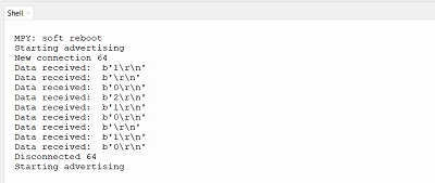
On the BLE central device side (mobile phone), I downloaded the Serial Bluetooth Terminal app as it’s easier to find the same MAC address once it’s paired up with that device.
Once I let the peripheral device start adversizing, the app detected the peripheral device. I selected the one to pair up and then the new terminal window appeared. I could read the record of serial communication between the BLE central and peripheral devices. It succeeded in turning on and off the on-board LED and the buzzer by writing “1” to send to the peripheral device. Then the peripheral device also retured the message to the central device.
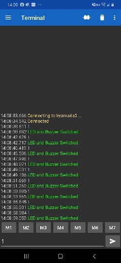
Comparing the program with the previous one which didn’t work, one big difference was that I added “machine” to the line to assign specific pin as output pin.
led = machine.Pin("LED", machine.Pin.OUT)
Test2 Control On/Off with Different Messages: The next step is to modify the program so that I could control the switch with two different texts: “1” for switching on and “0” for switching off. To do this, I added two more branches for the received data.
    # Import necessary modules
    from machine import Pin
    import bluetooth
    from ble_simple_peripheral import BLESimplePeripheral

    # Create a Bluetooth Low Energy (BLE) object
    ble = bluetooth.BLE()

    # Create an instance of the BLESimplePeripheral class with the BLE object
    sp = BLESimplePeripheral(ble)

    # Create a Pin object for the onboard LED and the buzzer configure it as an output
    led = machine.Pin("LED", machine.Pin.OUT)
    buzzer = machine.Pin(0, machine.Pin.OUT)

    # Initialize the LED state to 0 (off)
    led_state = 0
    buzzer_state = 0

    # Define a callback function to handle received data
    def on_rx(data):
        print("Data received: ", data)  # Print the received data
        if data == b'1\r\n':  # Check if the received data is "1"
            led.on()
            buzzer.on()
            sp.send("LED/Buzzer ON\n")  # Send a confirmation message
        elif data == b'0\r\n':  # Check if the received data is "0"

            led.off()           # LED off
            buzzer.off()
            sp.send("LED/Buzzer OFF\n")  # Send a confirmation message
        else:  # Check if the received data is other than 0 or 1
            sp.send("Do Nothing\n")  # Send a confirmation message

    # Start an infinite loop
    while True:
        if sp.is_connected():  # Check if a BLE connection is established
            sp.on_write(on_rx)  # Set the callback function for data reception
Then this is the result I got. Looks like I succeeded in turning on by sending “1”, and off by sending “0”. Also, if I send the other texts, the peripheral device returned the message “Do Nothing”.
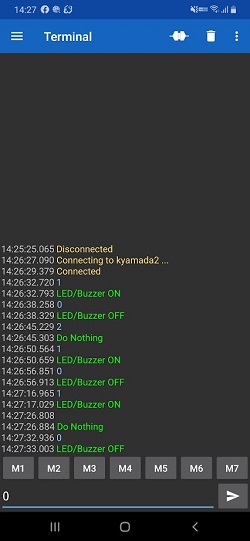
Sorry about the video which only shows the reaction of the peripheral device after I sent the message to turn it on. That’s all I could do with the only one on-board camera available.
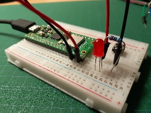
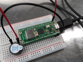
Test3: Replicate It with My Board: Finally, the last test is to replicate it with the board I developed. First, I connected the wires and the active buzzer between the bread board and the Alarm Device already made for my Final Project. I assigned the Pin1 as the output pin for the active buzzer.
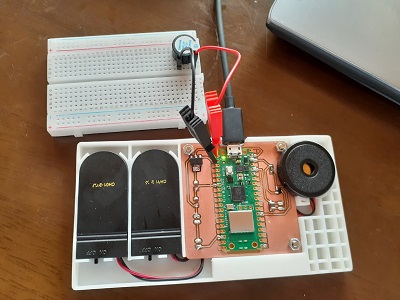
For this, I copy-and-pasted the above code to the main.py file for my board with a slight change in line 14 so that I could allocate pin1 for output pin for the buzzer.
buzzer = machine.Pin(1, machine.Pin.OUT)
When I uploaded the program and connected it with my mobile app, both the app and the pyothon shell of the Thonny IDE started recording the messages transmitted between the two devices.
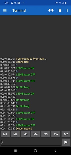
Here is the video to show how the on-board LED and the buzzer were responding. (My apologies again. I started recording the video after I sent the turn-on message to the peripheral device from my mobile.)
3-4. Preparation for Group Assignment (Updates on June 30, 2024)
In addition to exchanging messages between my board and the mobile phone in 3-3 above, I also did some preparatory work for the reading/writing messages between the boards we designed as part of our Group Assignment for Week13.
One of our boards was Seeed Xiao ESP32C3 programmed by Arduino IDE. Therefore, the Group Assignment should be between MicroPython language (for PicoW with Thonny IDE) and C++ language (for Xiao ESP32C3 with Arduino IDE). Before we directly jumped at this BLE connection between the two different languages, I thought that it would be a good idea to prepare programs for the BLE communication between two PicoW boards programmed in MicroPython languages.
Therefore, I prepared the two codes with Thonny IDE and saved them in each board.
| PicoW Board | BLE Role Assignment | Actions |
|---|---|---|
| Board for Final Project | Peripheral | - Read the temperature data from the on-board sensor. - Send messages about the temp data |
| New PicoW with Breadboard | Cental | - Receive messages about temp data. - Print the messages on the Serial Plotter. |
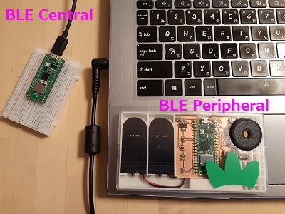
BLE Peripheral
The following program is prepared in the file name main.py and saved in the PicoW board used for my Final Project. Once I finished flashing. I disconnected it from the USB cable so that it could start reading the temp sensor and also BLE advertising once I switch on the coin battery holders.
    #BLE Peripheral Reading the On-Board Temp Sensor Values
    from micropython import const
    import uasyncio as asyncio
    import aioble
    import bluetooth
    import struct


    # UUID Definition
    _ENV_SENSE_UUID = bluetooth.UUID(0x181A)  # org.bluetooth.service.environmental_sensing
    _ENV_SENSE_TEMP_UUID = bluetooth.UUID(0x2A6E)  # org.bluetooth.characteristic.temperature
    _ADV_APPEARANCE_GENERIC_THERMOMETER = const(768)  # org.bluetooth.characteristic.gap.appearance.xml

    _ADV_INTERVAL_MS = 250_000  # Advertising interval (ms)


    # Registration of GATT Server
    temp_service = aioble.Service(_ENV_SENSE_UUID)  # Define the service
    temp_characteristic = aioble.Characteristic(
        temp_service, _ENV_SENSE_TEMP_UUID, read=True, notify=True
    )  # Setting of the Temp Read Characteristic (reading possible, notify possible)
    aioble.register_services(temp_service)  # Register temp server

    sensor_temp = machine.ADC(4)  # Define PIN for taking data from On-board Temp Sensor
    conversion_factor = 3.3 / (65535)

    # Define temp read from On-board Temp Sensor
    def _read_temperature():
        reading = sensor_temp.read_u16() * conversion_factor
        temperature = 27 - (reading - 0.706)/0.001721
        return temperature


    def _encode_temperature(temp_deg_c):
        # Encode temp sensor values to the transmittable format
        # To be more specific, it goes throught the following process.
        # - Multiply Temp Sensor Values by 100 so that they could be read as integer value
        # - Convert the bytearray to binary code for packing

        return struct.pack("<h", int(temp_deg_c * 100))


    async def sensor_task():
        # Renew the temp sensor values after writing
        # - Read temp sensor values
        # - Write them in the Characteristics
        # - Pause for 1000ms
        while True:
            t = _read_temperature()  # Read temp sensor
            temp_characteristic.write(_encode_temperature(t))
            await asyncio.sleep_ms(1000)


    async def peripheral_task():
        # Keep advertising until connected
        # When connected, write its MAC address on the BLE central device
        # Wait until it's disconnected
        while True:
            async with await aioble.advertise(
                _ADV_INTERVAL_MS,
                name="mpy-temp",
                services=[_ENV_SENSE_UUID],
                appearance=_ADV_APPEARANCE_GENERIC_THERMOMETER,
            ) as connection:
                print("Connection from", connection.device)
                await connection.disconnected()


    async def main():
        # Define the function to undertake the two tasks in async
        # t1(task1):Renewal of the Temp Sensor read
        # t2(task2):Tas as BLE Peripheral
        t1 = asyncio.create_task(sensor_task())
        t2 = asyncio.create_task(peripheral_task())
        await asyncio.gather(t1, t2)


    asyncio.run(main())
BLE Central
The other code is for the BLE central device, another PicoW board on the breadboard. It could be connected to the PC via USB cable. This code is saved in the PicoW board as temp_client.py file.
    #BLE Central Device to Receive Temp Data and Plot it on the Console
    from micropython import const
    import uasyncio as asyncio
    import aioble
    import bluetooth
    import struct

    # UUID definition
    _ENV_SENSE_UUID = bluetooth.UUID(0x181A)  # org.bluetooth.service.environmental_sensing
    _ENV_SENSE_TEMP_UUID = bluetooth.UUID(0x2A6E)  # org.bluetooth.characteristic.temperature


    # Helper to decode the temperature characteristic encoding (sint16, hundredths of a degree).
    def _decode_temperature(data):
        # Function to decode the received data to temp sensor value
        # More specifically, it defines the following tasks:
        #・unpack the binary code
        #・divide the temp sensor value by 100
        return struct.unpack("<h", data)[0] / 100


    async def find_temp_sensor():
        # Scan the advertising devices for 5 sec.
        async with aioble.scan(5000, interval_us=30000, window_us=30000, active=True) as scanner:
            async for result in scanner:
                # If the target device is named "mpy-temp" and incuding env sensing, returns the device info.
                if result.name() == "mpy-temp" and _ENV_SENSE_UUID in result.services():
                    return result.device
        return None


    async def main():
        device = await find_temp_sensor()
        if not device:  # If it fails in detecting the target device
            print("Temperature sensor not found")
            return

        # If the target device is detected, the following taskes will also be undertaken
        try:
            print("Connecting to", device)
            connection = await device.connect()  # Connecting to the BLE peripheral device
        except asyncio.TimeoutError:
            print("Timeout during connection")  # Post message if the connection timeout error occurs
            return

        # When successful in device.connect(), proceed to the following tasks as well
        async with connection:
            try:
                temp_service = await connection.service(_ENV_SENSE_UUID)  # Environmental sensing service
                temp_characteristic = await temp_service.characteristic(_ENV_SENSE_TEMP_UUID)
            except asyncio.TimeoutError:
                print("Timeout discovering services/characteristics")
                return

            # If the BLE central device reads the characteristics of the peripheral, proceed to the following tasks.
            while True:
                temp_deg_c = _decode_temperature(await temp_characteristic.read())  # Decode temp sensor data from received data
                print("Temperature: {:.2f}".format(temp_deg_c))  # Plotting the temp read on the Plotter
                await asyncio.sleep_ms(1000)  # Sleep for 1000ms


    asyncio.run(main())
Result
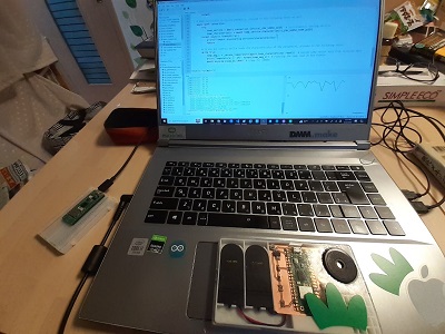
Once both devices were ready, I switched on the Alarm Device (BLE peripheral), and then clicked “RUN” on the Thonny IDE for the other PicoW on the breadboard (BLE central). Immediately the Python Shell started printing the serial data and also the Plotter started plotting the temperature data transition on the Thonny IDE.
Based on these program set, I proceeded to the Group Assignment and the test result was documented in the Group Assignment page.
Acknowledgement: This practice was made possible with the sample codes available on the website Raspberry Pi Pico WでBLE通信を使ってみる(micropython).