2. Computer-Aided Design
Weekly Highlight (January 31 to February 7)
Collected the data on the number of incidents that the Japanese officials working for JICA programs had their passports lost or stolen annually.
Went through the literature survey on the Bluetooth Lower Energy (BLE) device and also took advice from the early achiever on the items required for the final project.
Studied 2D and 3D CAD and did some exercises for design of the final project in the future. Spent too much time in familiarizing to Photoshop and Illustrator. Couldn’t do much on GIMP, Inkscape, Onshape and Solidworks.
Compressed two video files, including the one on the animation with Fusion360.
Celebrated setsubun for the arrival of the early spring together with the other Fab Academy student and the instructor at FabLab Kannai during the local session, eating a giant eho-maki roll.

Individual Assignments Overview
Here is the list of individual assignments given by the instructors:
 - Model (raster, vector, 2D, 3D, render, animate, simulate, ...) a possible final project,
 - Compress your images and videos,
 - Post a description with your design files on your class page
Learning About 2D Design
We learned that there are two types of 2D design data: raster and vector.
1. Raster: Raster files are the images that combine a large number of pixels, which are small colored squares, to form a high-resolution image, such as a photograph. The more pixels, the higher the quality of the image, and the fewer the pixels, the lower the quality of the image. JPG and PNG are the two most common file formats for raster data. Raster images cannot be scaled without affecting the quality of the images. If we zoom in, the shapes and borders will be blurred.
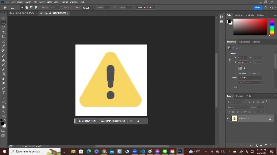
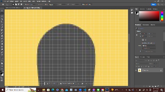
The above two images are the screenshots I took when I opened the JPG file “Alert” on Adobe Illustrator. As I zoomed in, I found that the image consisted of a number of pixels.
2. Vector: Vector files use mathematical formulas, lines, and curves to display an image. Vector files have no pixels. Using mathematical formulas, vector files could represent shapes, borders, and fill colors to construct the image. Vector images can be scaled without affecting quality as they can be recalculated even if their size changes. SVG is one of the most common file format for vector data.
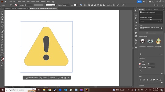
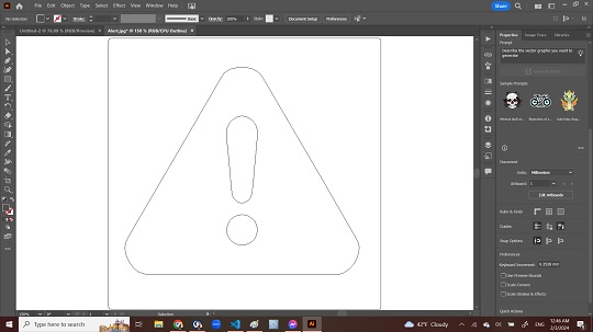
I opened the same JPG file on Adobe Illustrator. First, I searched for the “image trace” command in the menu bar and expanded “Object” and found the “Image Trace”. Once I selected “Expand”, I got the Context Task Bar under the object on the art board. By manipulating the Context Task Bar and Property Panel on the right-hand side of the art board, I could somehow converted image tracing and got the outline of the image.
3. Adobe Photoshop: Although I had been subscribing Adobe Creative Cloud primarily to use Premiere Pro for video editing, I had not used Photoshop before. After a few trials on GIMP for 2D drawing, I decided to explore more on Photoshop. I went through the online tutorials on YouTube the whole Sunday on February 4 and learned 2D drawing by making a few designs:
- Sample Cover of the Card Tag for Final Project: On a trial basis, I started with designing the cover of the card tag for the anti-theft alarm system. I downloaded the free image files and opened them and placed them on two different layers. The first one is the electronics circuit board, and the second one is the famous art work “Great Wave in the Offshore of Kanagawa” by Katsushika Hokusai. The original landscape was just blue sky and I tried to add the image of circuit board.
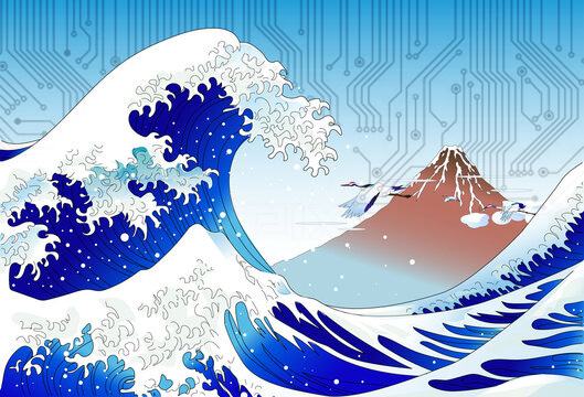
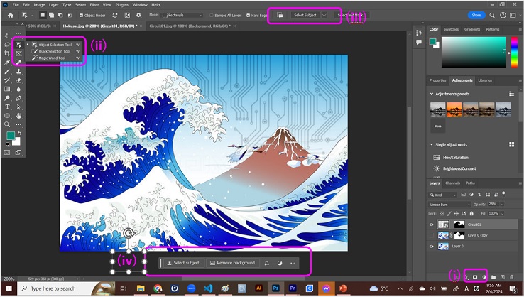
The most difficult part of this trial was the layer masking, dividing the landscape and sky. For this, I used the (i) Layer Mask for the target layer, and then selected the (ii) Object Selection Tool in the Tool Bar. Then I clicked the (iii) “Select Subject” box in the Control Panel to show (iv) Context Task Bar under the object. Then I manipulated in the Context Task Bar to decouple the landscape image. After a few trials and errors, I found that I could do it by duplicating the landscape layer and applying two different layer masks.
- 2D CAD of the Project Idea Sketch: Then I proceeded to convert my hand-drawn project idea sketch to the 2D CAD drawing. I must confess that the image for thief was downloaded from open-source platform Irasutoya. For other images, I designed from scratch.


Most time-consuming part of this exercise is moving from one layer to another. It took much time to understand that the first step to master Photoshop, and probably GIMP as well, would be to understand the layers.
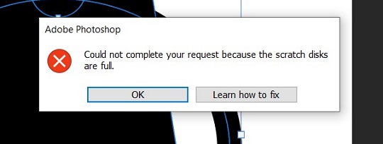
One error message I frequently faced was about “full scratch disk”. I clicked “Learn how to fix” and followed the instructions on the Adobe website. (Windows icon > Settings > System > Storage, and then I purged temporary files and uninstalled unused app. ) Probably you may follow the instructions described in the following website as well: DW Photoshop “How To Clear Your Adobe Illustrator Scratch Disk”.
- Compress Final Project Image: Although I’m not sure if I understood the meaning of image compression described in the assignment, at this point of time, here is the overall image of my final project. The detailed design of the Bluetooth Low Energy device is yet to come.
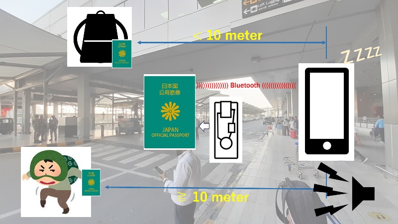
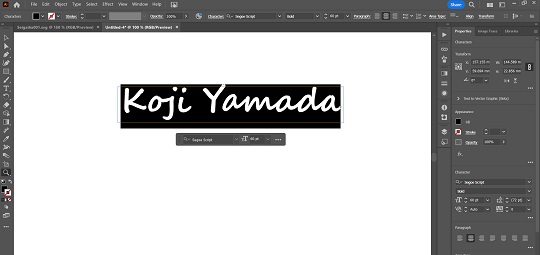
4. Adobe Illustrator: I used to be a user of CorelDRAW. But since I have been subscribing Adobe Creative Cloud for Premiere Pro, I have decided to learn vector data production with Illustrator. For this 2D-drawing practice, I decided to prepare two data in terms of SVG file. Since my project is to design the BLE device attached to official passport, I thought there could be three possible ways to do it:
- Small card (as small and thin as a credit card), which could be inserted into the vinyl pocket of the passport holder.
- Leather cover, which could wrap up the whole official passport like a book cover.
- Small box, which could have the BLE device monted inside and could always be carried in a backpack, a handbag or any other bag we always carry together with other valuables, such as wallet.
Currently my aspirational target is a small card or a leather cover while I am thinking of starting with a box and then downsizing it. Therefore, as a practice for the future design, I decided to work on the cover design for the card and the leather cover.
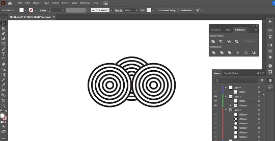
- Sample Cover v.2 of the Card Tag for Final Project: As for the cover design, I already made one design with Photoshop. This time I tried to draw another traditional Japanese design pattern called seigaiha, which means “blue wave”. It’s a pattern of concentric arcs arranged in a scaly pattern.

Seigaiha Sample Image from Akiko Yamagata
Therefore, the first step for the design was to draw concentric arcs:
 - Diameters as multiples of 5.
 - Black Stroke as 3 pt.
 - Always set the infill color in white.
 - Perhaps you have to rearrange the layers for the smaller arcs
   could be visible on the larger arcs.
After completing the first set of the concentric arcs, I selected all the arcs and grouped them. After that, I duplicated two more sets, grouped each of them, and placed them under the first set as described in the figure below:
After grouping all of them arcs, I drew a rectangle to cover the area to be used for making the pattern. Then I went to the “Object” in the menu bar and selected “Clipping Masks” only to show that area.

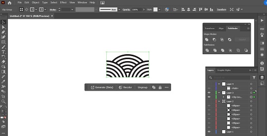
The last step was to duplicate the area side-by-side horizontally. After completing the horizontal pattern making, I selected all the pattern images and duplicated once again. Placing the duplicated images vertically, I could reach the seigaiha design.
However, here I noticed one critical design failure. If I go for cutting the black areas, all the remaining white areas should be interconnected. In other words, all the black areas should always be separated. To achieve this objective, I decided to revert the first concentric arcs and add another white arc outside the largest black arc. Then I followed the same operations described above and reached the image I wanted. :
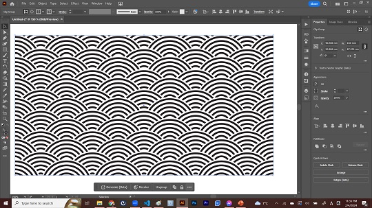
Now that I got a satisfactory image, I exported the design data in terms of SVG file for further design on the 3D CAD.
- Preparation for Computer-Controlled Cutting (Gold Foil Stamping): One great feature of the FabLab Kannai, our local Fab Academy node, is that it has a cutting machine that could cut out and stamp gold foil on leather or vinyl sheet. Since we are supposed to work on computer-controlled cutting next week, I also made a text data for cut-out:
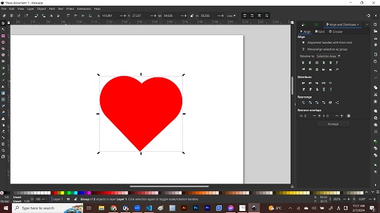
5. CorelDRAW, GIMP and Inkscape: In addition to the above journey with Adobe Photoshop/Illustrator, I tried other 2D CAD programs as advised by my instructors. They said that the Adobe CC monthly subscription might not be affordable for many of my peers in other countries in Asian and African Regions and therefore I should have the alternative platform on which I could communicate with my peers. I did a lot with CorelDRAW before I took Fab Academy and still feel that it is more familiar to me. Perhaps CorelDRAW could still be my first option. However, CorelDRAW is not free, either. Therefore, I tried other free-downloadable 2D CAD programs: GIMP and Inkscape. I tried to see how long it would take to design a heart shape without reading tutorials. It may be too early to decide, my temporary conclusion was Inkscape is more friendly to me than GIMP in the sense that I had hard time finding the way to select objects for coloring or cancel the object selection on GIMP while I could do it almost intuitively on Inkscape. During the Fab Academy, I would use Inkscape to work on my assignments.
Learning About 3D Design
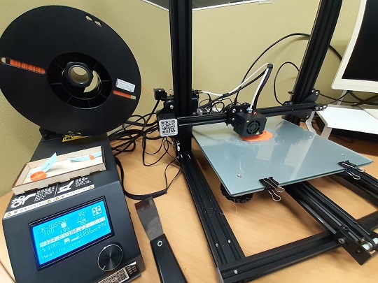
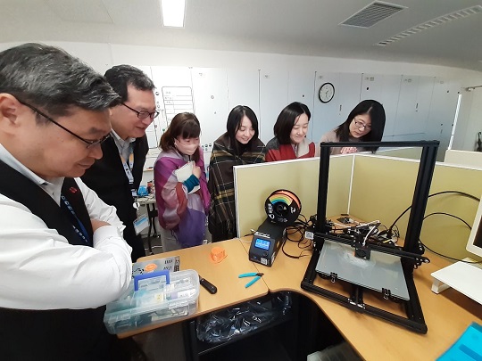
Since January 25, I have been hosting a hands-on workshop on 3D modeling in my workplace. As soon as I joined in my new workplace, I remembered that there was a 3D printer in the store room, which they purchased a few years ago for the purpose of the display of new technology that could be applied to international development and UN Sustainable Development Goals (SDGs). But after the event, it has been left underutilized and many staff who could operate the machine left the office. I wanted to use it for a while for my own sake and also wanted to share my knowledge and experience with the other staff. I got the concurrence of the officer-in-charge and brought the machine to my desk. This workshop series will cover 3D CAD with Tinkercad and be hosted until the end of March.
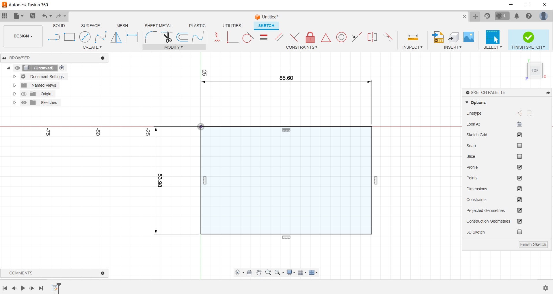
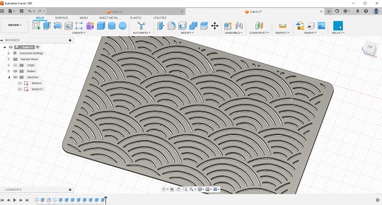
1. Fusion360: In my previous assignment at FabLab CST in Bhutan, I used to use Tinkercad and Fusion360. Also, learned Solidworks a bit. If it’s a credit-card size device, there will be just a slight possibility to work on 3D CAD. While I may go for designing of the small box to have my device mounted in the future, at this point of time, I just worked on the design of the flat card with seigaiha engraved on the surface, with my most familiar program, Fusion360.
First, I switched to creat-sketch mode, chose the X-Y Plain, and drew a rectangle with a credit-card size of 85.60mm by 53.98mm.
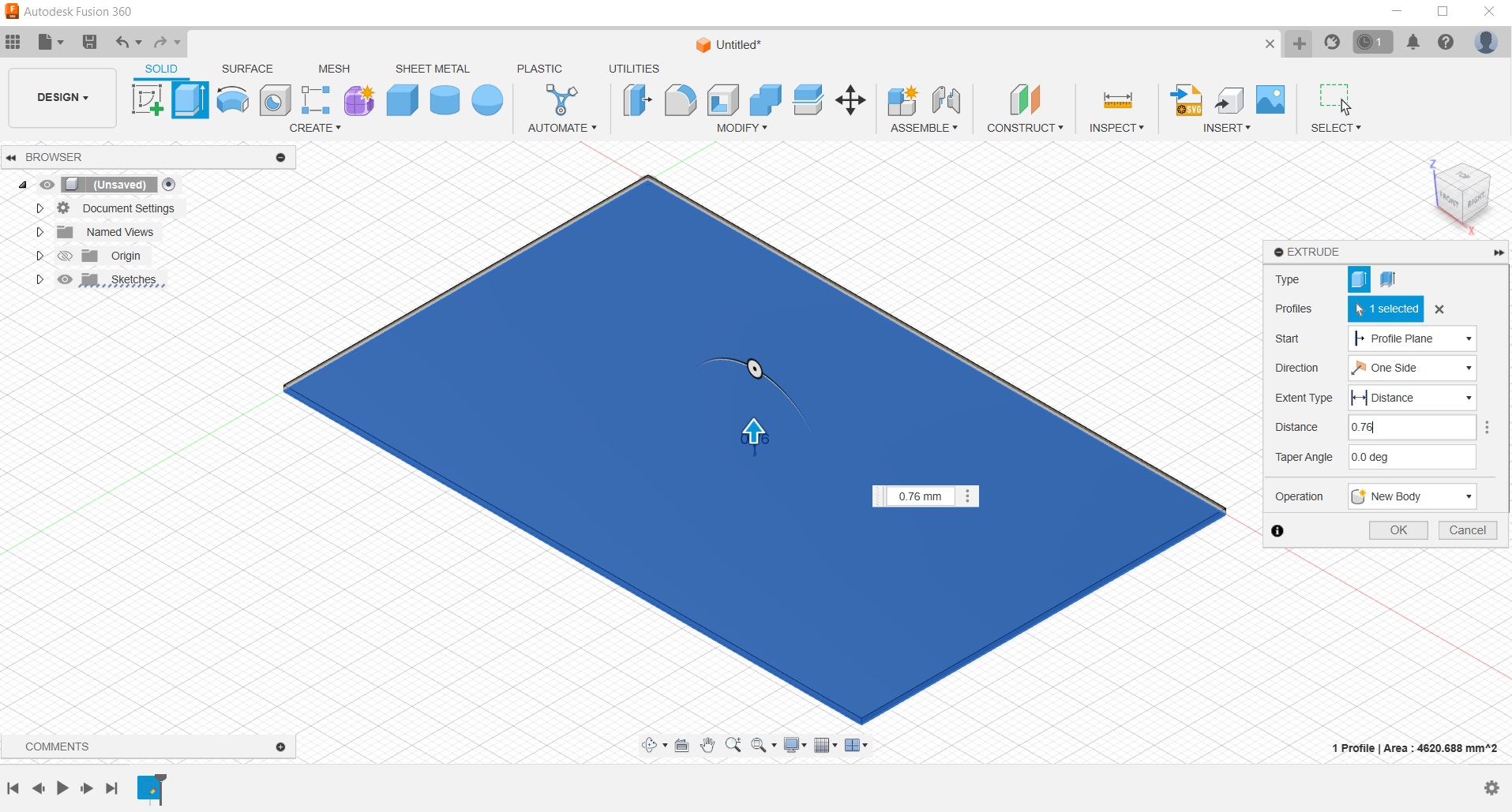
Then I finish sketch mode. After choosing the profile, I clicked the “Extrude” icon on the Tool Bar and vertically extruded by 0.76mm. Of course, as I further proceed to the design of the device, perhaps the device would be thicker than this. This could be modified at the later stage.
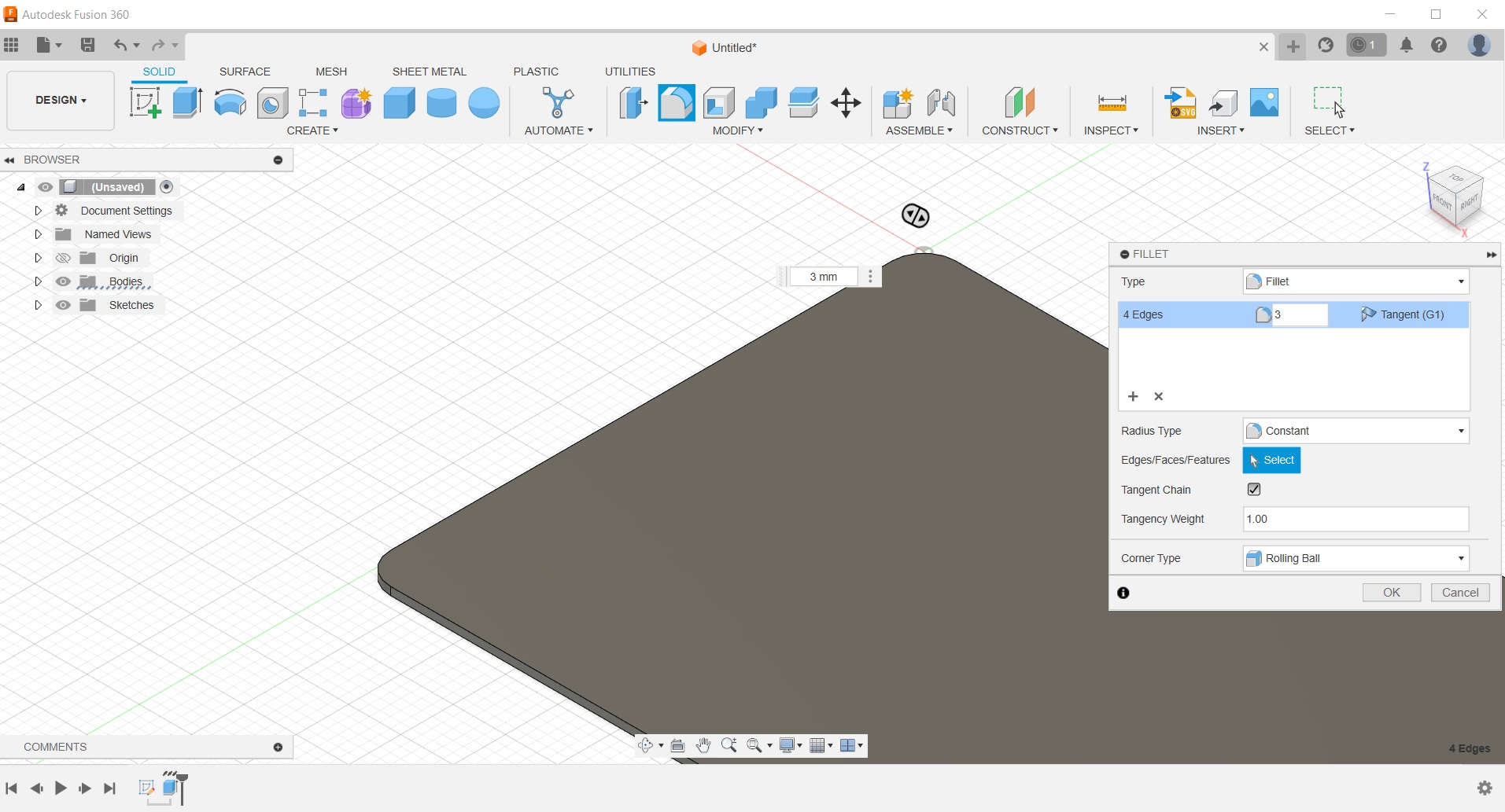
As the usual step after the extrusion, I rounded all the four corners of the card by adding 3mm fillet.
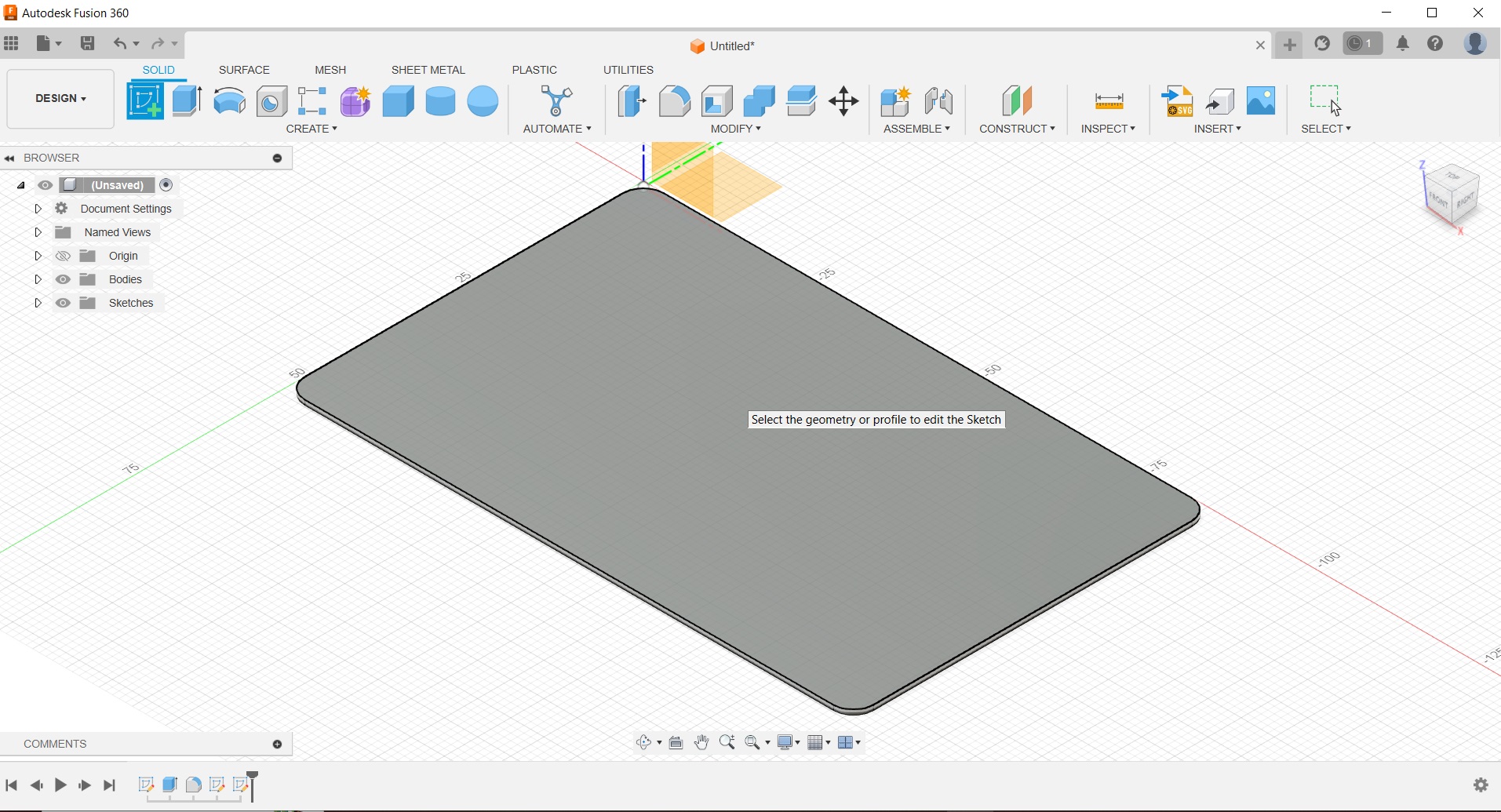
Now the main body is ready. Then I thought that all I had to do is import the SVG file data on the surface of the card, choose the profiles and extrude them. Soon I faced a series of problems.
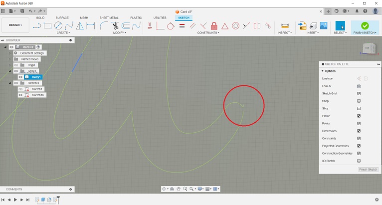
- Problems Faced (I): The first problem occurred when I tried to insert the SVG file of seigaiha. When I created the SVG file on Illustrator, I made a rectangular cut-out data by using the “Clipping Masks” feature, and then exported it. However, when I imported the SVG file to the Fusion360 sketch plain, the outline of all the concentric arcs appeared on the sketch plain.
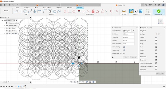
It seemed that the rectangle remained in the center of the imported sketch. However, when I checked the design on Illustrator, I found that full concentric arcs also remained in case they have the overlaps with the rectangular cut-out. This means that even though they were not visible, the full arcs were still there.
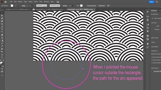
I tried to find the way to get the rectangle separeted from the other remaining paths. Spending a couple of hours, I finally decided to give up and go for an alternative option: Exporting the data in terms of JPG file. Then I placed the image data in the new art board for “Image Trace”. And I could get the outline for exporting in terms of SVG file.
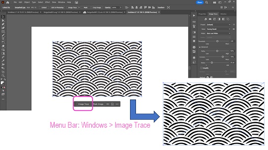
But this is only a temporary measure. If we convert the design to bitmap once, we have to compromize on the quality of the outline trace as described in the above figure. The outlines I got were far from satisfactory, but I inserted the SVG file to the sketch plain on Fusion360 and this time the image insert was successful. I clicked all the profiles covered by the outlines,and extrulded negatively for engraving. I still feel I need to improve the way I design it.
- Problems Faced (II): I also tried to insert the text image to the sketch plain on Fusion360, based on the SVG file I created in the 2D design exercises. I did the image tracing to convert the text to the outline data on Illustrator, and exported it in terms of SVG file. File insert to the sketch plain was not difficult. But when I tried to select all the profiles for extrusion, I found that I could not select some of the profiles. In Fusion360, once I point the mouse cursor to the profile enclosed by the outline, that profile turns blue. But it didn’t happen to four profiles. For your information, I tried to import the data onto Tinkercad, and it went well.
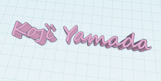
What’s wrong with the data? The fact that some of the profiles didn’t turn blue means that the profiles were not closed with outlines. Therefore, I zoomed in to the sketch plain to see if the had their outlines disconnected somewhere.
I found it! I found that the outlines were disconnected for the non-functioning profiles. I thought of a couple of options to rectify the problem. The most simple solution is just connecting the outline by drawing a straight line or a curve from one broken point to another.
Now all the profiles turned blue. This time I tried emboss.
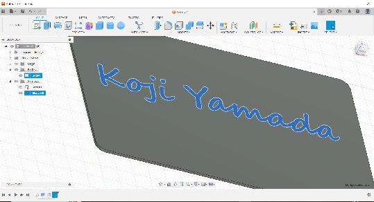
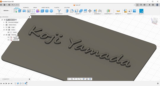
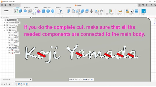
As long as I go for emboss the text, there is no problem. However, if you choose to cut the text, you have to make sure all the essential components are commected to the main body.
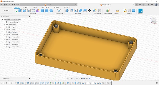
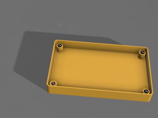
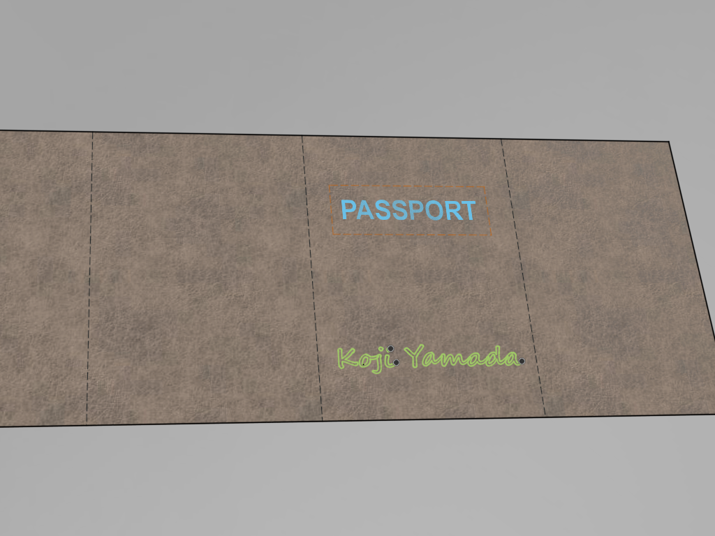
- Rendering with Fusion360: As for the rendering exercises, I designed a small box for mounting the Bluetooth Lower Energy device. Added four screw holes and screws, and assembled them. Also, I have tried rendering the passport holder to be made of leather with laser-cutouts on the cover. It didn’t look nice because it didn’t require any extrusion for the text profiles on the surface.
- Animation with Fusion360: In addition to rendering, I also tried to make an animation video for the box for BLE device. Learned how to edit by doing. When I published the animation, the data was created in terms of AVI file. I followed the same procedure described later in the section of “Data Compression of Videos”. For the troubles I faced during the data compression, please see the following section. In fact, it took longer time for compression than for making data itself.
2. Tinkercad: In fact, I had been a heavy user of Tinkercad when I had been working on the STEAM education delivery for primary and secondary school students during my previous assignment in Bhutan. It’s a browser-based entry model and I understand that we should go for more advanced programs.
3. Blender: To be added later. I have operated it a bit but too little time to say something about it.
4. FreeCAD and Onshape: Our instructor also advised me to try using FreeCAD and Onshape before I decide to stick to Fusion360. Although I started operating it, it’s too early to write about it.
5. Solidworks: According to my past experience, probably Solidworks is the best option for 3D design. Compared to Fusion360, Solidworks has a better assembly function and it’s easier to make 2D sketch drawings of the 3D object. However, I experienced a series of failures in downloading the free program in 2022 with my PC. I downloaded it in another laptop and did a lot of exercises. Since then, I have been using Fusion360 primarily. I’m still using the same PC since 2021 and not so sure if Solidworks runs well this time. *To be added later.
Data Compression
During the first few sessions, the instructors have frequently reminded that each candidate would only have 10MB for Git push. In the last global session on Wednesday, January 31, Prof. Neil also emphasized this and showed us the Students Repository Sizes List. Whenever we post images and videos, we have to be aware of this limit and try to compress the data as much as possible.
1. Image Compression: For image compression for my blog and websites, I have used Windows Paint Accessory for so long. Our instructor recommended ImageMagick. I downloaded exe file and tried it.
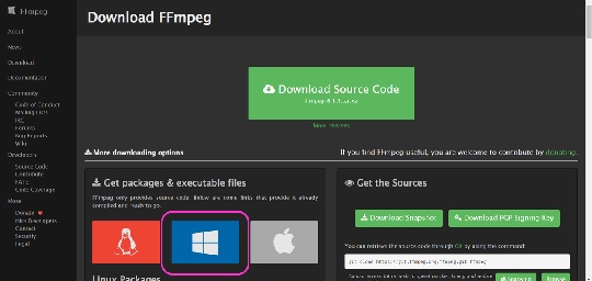
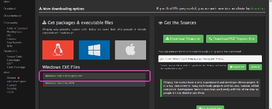
2. Video Compression: Our instructor recommended [FFmpeg] (https://ffmpeg.org/) and we downloaded the files. I went to FFmpeg website and clicked the Windows logo, and then clicked “Windows builds from gyan.dev” and moved to CODEX FFmpeg webpage. There I chose the Git full build package.
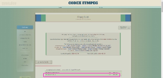
The Git full build package needs unzipping. For this, I needed to download another unzip program (7Z Opener). Once completing unzipping, I cloned all the files and saved them by creating “ffmpeg” folder under “C:\Users\quant".
- Work with Windows PowerShell: Here I opened the Windows PowerShell and confirmed that the Git full build package was successfully place in the above directory.
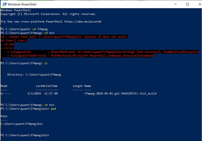
Once I created the “C:\Users\quant\ffmpeg\bin” path, I had to take time and set up an “environment variable” in my Windows 10 system:
An environment variable is a user-definable value that can affect the way running processes will behave on a computer. Environment variables are part of the environment in which a process runs. For example, a running process can query the value of the TEMP environment variable to discover a suitable location to store temporary files, or the HOME or USERPROFILE variable to find the directory structure owned by the user running the process.wikipedia
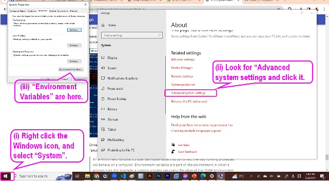
For path setting, I took the following procedures: (i) Right-click the Windows icon and then click “System” to open the control panel; (ii) Click “Advanced systems setting” and opened the “Systems Property” window; and then (iii) Find the “Environment Variables” button and click it.
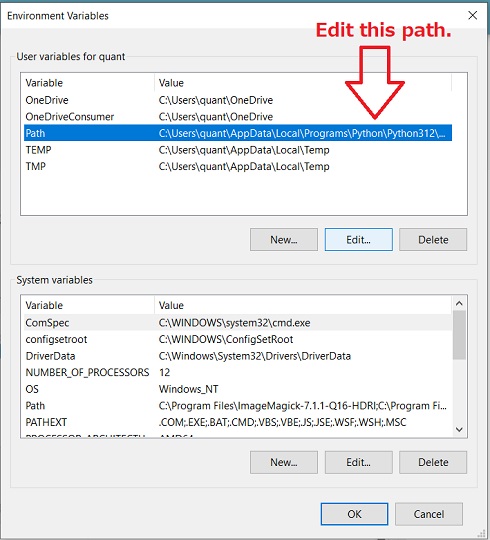
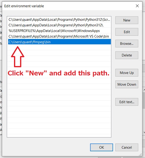
Then in the “Environment Variables” pop-up, I did:(iv) Point at the “Path” in my user variables and click “Edit”; and (v) In the “Edit Environment Variable” pop-up, click “New” button and add “C\Users\quant\ffmpeg\bin” path.
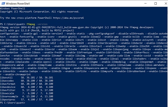
Now I am back to Windows PowerShell. I could check the FFmpeg version by “C\Users\quant >ffmpeg -version” and here is the result:
- Encoding with VS Code: Now I am back to VS Code editor. While the above process on the Windows PowerShell was for setup and one-time process (easy to forget and therefore worth memorizing), the encoding on the code editor was the process I should repeat almost every week. Had to learn by doing, but in the beginning I made a lot of mistakes.
The encoding process is simple.
- (i) Prepare the video file: Any video editor is accepted.
- (ii) Save the video file in the local video folder.
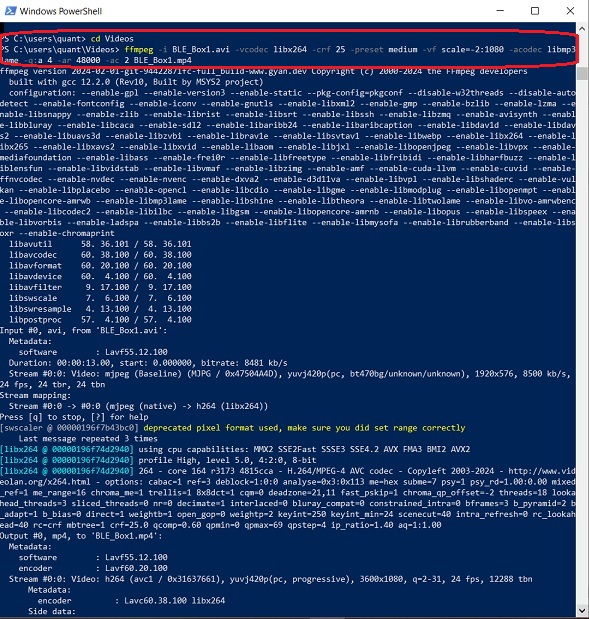
- (iii) Just write the following command in the terminal, replacing “input_video” with your video file name, and “output_video” with the new video name you want:
ffmpeg -i input_video -vcodec libx264 -crf 25 -preset medium -vf scale=-2:1080 -acodec libmp3lame -q:a 4 -ar 48000 -ac 2 output_video.mp4
The first problem I faced was that I couldn’t set the right path to read the input video file. Our instructor advised me that it doesn’t matter where we save the video file. The new encoded file is created in the same folder. So I saved my video files in the “Video” folder. But it took me much time to find that “C\Users\quant\Video” is the right path I wanted.
Now the encoding is completed, next step is writing a code for pushing to repository. This is the last step.
- (iv) Import the encoded file to the code editor.
- (v) Do as we do when we insert image files to the markdown texts.
Now I faced the second problem. Even though I inserted the video file and pushed to local repo, I could only get the video frame but the video was not visible.
<video controls src="Images/GoogleEarthPro001.mp4" title="Title" width="600" ></video>
Then our instructor advised me to add “../” before the video file name as shown in the following screenshot.
<video controls src="../Images/GoogleEarthPro001.mp4" title="Title" width="600" ></video>
Now it’s working. First I tried encoding with the existing video file I made a few months ago (route map from the location of FabLab CST to Gedu, in Bhutan) and here is the result. Based on this experience, I tried to convert the animation I created with Fusion360 to the encoded file as already shown above.
List of Design Files Created
2D
Photoshop: Hokusai “Big Wave” / Passport / Mobile Phone / Device / Backpack / Alarm / Bluetooth
Illustrator: Seigaiha / My Name
3D
Fusion360: Card Design Seigaiha / Dard Design “My Name” / Passport Cover Design / BLE Box Design