7. Computer-Controlled Machining
Assignments Overview
Here is the list of individual assignments given by the instructors. As for the Group Assignment, please see the Group Assignment page on the FabLab Kannai website:
  > Make (design+mill+assemble) something big (~meter-scale)
  > [Extra Credit]: Don’t use fasteners or glue
  > [Extra Credit]: Include curved surfaces
1. Preconditions
We had been reminded since two weeks ago that we had to come up with an idea on the thing to make with a large CNC milling machine. It could be something practical and I had thought of making a bookshelf which could be perfectly fit to my requirement to use it in my study room at home. However, in our assignment, there were the following conditions on the material and the machine:
Material Thickness: typically 9-12mm (it depends on your choice in a shop)
Material Size: 910mm x 1,820mm x 2 pieces (Group x1, Individual x1)
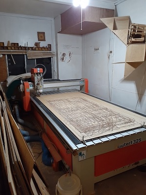
Machine: CNC Router ZN1325
End Mill: Straight, 6mm
Software: CUT2D (for making G-code) / Mach3 (for controlling CNC)
Location: FabLab Hamamatsu/TAKE SPACE, Hamamatsu City, Shizuoka
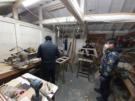
Because our lab, FabLab Kannai, didn’t have a large CNC router, our instructor consulted with the manager of FabLab Hamamatsu and made an arrangement for us to have a hands-on local session in Hamamatsu in one day on Saturday, March 9. It takes two hours to reach the lab from Tokyo even by bullet train. If we leave Tokyo/Yokohama at 8 am and take the hands-on session starting at 10 am, we have to complete all the assingments by night and take the last train at around 9:30 pm in the evening. We have to be very efficient to take full advantage of this opportunity.
That made us feel we had to be very proactive. After the global session on Wednesday, we took a local session online on Thursday. We got our first design ready by the local session. And after the consultation with the local instructor, we had to brush up the desing and get the data ready by the time we visited FabLab Hamamatsu.
2. Product to Make
As mentioned above, at the earlier stage I had been thinking of making a cutomized bookshelf. However, considering the above preconditions, I decided not to. The bookshelf must have a backboard and it doesn’t have to be as thick as 9-12mm. If I choose to use the material of 9-12mm thickness and cut out the backboard from it, it may cause extra weight and that makes it diffisult to carry and bring it back to Tokyo/Yokohama. Another weakness was the use of the hinges. I understood that we were supposed not to use fasteners and glue. By the same token, we were probably not allowed to use hinges.
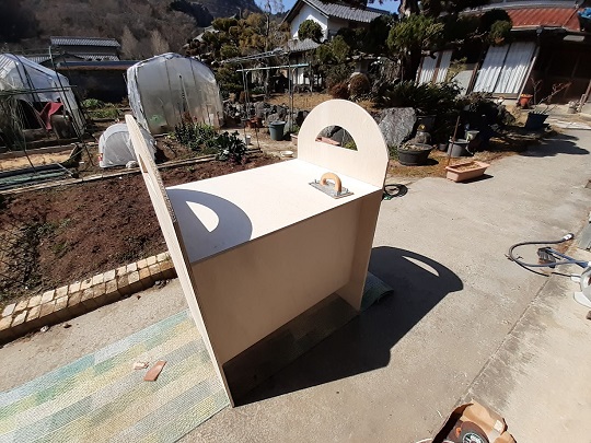
Therefore, immediately after the global session, I decided to go for the alternative design and take the advice from my family. My wife said she wanted a portable sales stall to sell the vegetables she and her parents-in-law harvest in their kitchen garden. Also, it could be used to set up a pop-up shop in the ad hoc free market events.
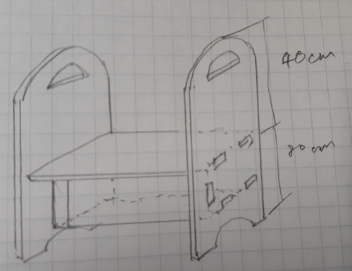
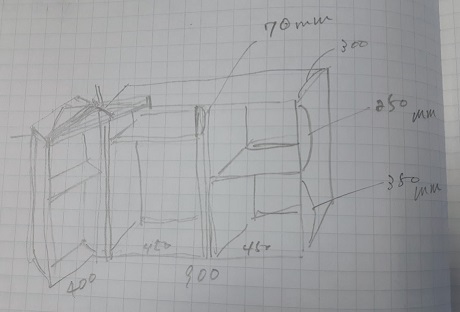
Before I proceeded to computer-assisted design, I set the following design principles:
  1. The table must be 800mm x 600mm;
  2. It must be 80mm high above the ground, following the product standard in Japan;
  3. It has the second layer below the table so that it could keep stock products or bags;
  4. This second layer is hidden by the front wall, on which we could put banners and posters.
3. Dogbone/T-Bone Fillets
In the meantime, since last week, our instructor had reminded us how to design the wood joint without glue or any other adhesive measure. He briefed us of dogbone fillets first and then added T-bone fillets later.
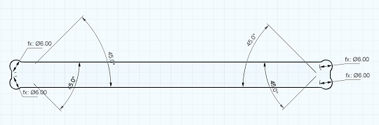
Dogbone fillets are added to both pockets/holes and plugs, by creating a circular hole at the neck of the plug and at each corner of the hole. The diameter of the circular hole is the one of the end mill. This is because when we cut the board with CNC router, we are not able to cut the inner corners sharper than the diameter of the cutting tool. This will cause the plug not to fit perfectly into the bottom of the hole. If we make the fillet at each bottomo corner of the hole, the plug could be slid deep into the hole.
Dogbone fillets should be added by drawing a 2-point circle outside (for plugs) and inside (for holes and pockets) of the target corner. The circle should coincide with the corner point and the center of the circle should be plotted along the 45 degree construction line from the corner point. The radius of the fillet (or the circle) is half of the diameter of the end mill.
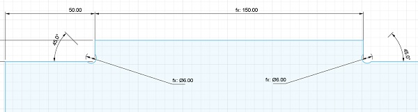
However, after the assembly, the dogbone fillets are visible. In order to reduce the visibility of such fillets, our instructor advised that there was an alternative measure, T-Bone fillets. 2-point circle is the same. But in this case, both the center and the periphery of the circle should coincide the straght line of the profile.
Again, I felt T-Bone fillets might have their cons. Making the T-Bone fillets on the plug is fine. But if the board is thin, we would not be able to draw two circles for each corner of the rectangle, and this might weaken the stability of the joint.
To recap on how to design these two fillets, the following YouTube video will be very helpful.
4. Design with Fusion360
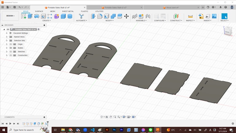
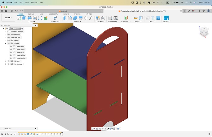
Immediately after the last global session, I started designing the portable sales stall with Fusion360. The above YouTube video and other tutorial videos showed that we could draw sketches on XY, YZ and ZX plains from the beginning and make a 3D shape. But I just simply drew 2D sketches on the XY plain. I only drew one sketch of the side wall. After all the four profiles were extruded, I made a mirror copy of one side wall. The first design looked like the one shown in the next screenshot.
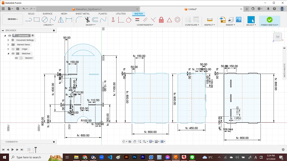
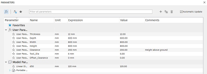
For this, I made a few sets of parameters. The most important one was the “Tool_Diameter” for the size of the end mill and “Thickness” for the thickness of the material.
     - Tool_Diameter: 6mm (diameter of the end mill);
     - Thickness: 12mm (thickness of the material)
After drawing the outlines of the four components as well as plugs and pockets, I added dogbone fillets. Although I trimmed all the unnecessary lines from my sketches, soon I learned that that’s not necessary for getting the outlines of the profiles I wanted.
Once completing the sketches, I selected the profiles and extruded them by thickness parameter.
5. Comments from the Instructors and My Reactions
During the local session on Thurday, March 7, I presented my design described above. Here are the comments from our instructors:
-
If it’s portable and disassemblable, firm wood joints might be crucial. It’s worth while to consider: (i) Loose-Wedge Mortise & Tenon Joints; and (ii) T-Slot.
-
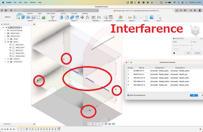
I must check if there is no interfarence between the components.
For the first comments, I did consider if I could reflect them in my final design. Perhaps T-Slot could be dropped for this particular assignment. With regards to the Loose-Wedge Mortise & Tenon Joints, I wondered how I should design the wedge to be cut out of the board which only has 12mm thickness. Maybe I could do it if I had plenty of time for redesign. But this time I decided to stick to Dogbone Fillets.
The interfarence check was made by our instructor, who detected interfarence at seven plugs and pockets.
Our instructor has also pointed out that although the number of the components was only 5, they were all very large and they would not be able to fit into the “910mm x 1,820mm x 2 pieces” requirement. He kindly agreed to make use of the remains of the board left by the previous batch Fab Academy student who took the hands-on session in Hamamatsu. But even so, total cutting area requirement was larger than the boards available.
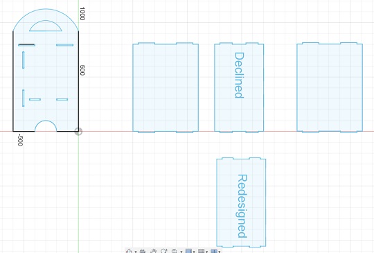
Therefore, I spent extra time for redesigning the stall. First, I took the measurements on the distance between the four plugs and pockets, and made readjustments on their locations. As for the three plugs and pockets for the front wall, I decided to do without them due to time constraints. Second, I reduced the height of the side walls so that one side wall and one 800mm x 600mm rectanglar components could fit to one board and ready for cutting.
This is my final design. After the extrusion of the profiles, I exported the svg files by Shaper Utilities plug-in.
SVG files: Table1 / Table2 / Front Wall / Side Wall1 / Side Wall2
F3D file: Portable Sales Stall Set
6. Woodwork
6-1. Data Preparation
Opening the Adobe Illustrator, I placed all the SVG data onto the same art board. We must be careful so that we would enlarge the art board to cover all the vector data. Otherwise, it could not be read and uploaded to the CUT2D software at FabLab Hamamatsu.
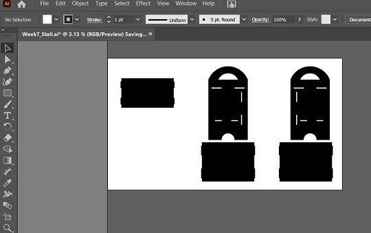
AI file: All the Components
6-2. Procurement of the Board
As soon as we arrived in Hamamatsu, we went out for a DIY center. There are a few such stores in our neighborhood in Japan: Cainz, Kohnan and Valor. Depending on the shops, we are able to cut the board there so that the materials could be accommodated in the customers’ vehicle. There were a few varieties of the boards in the shop. Because of the requirements of my portable sales stall, I picked up the falcata board. It’s white and good for displaying vegetables and handicrafts on it. Plus it’s one of the lightest wood materials.
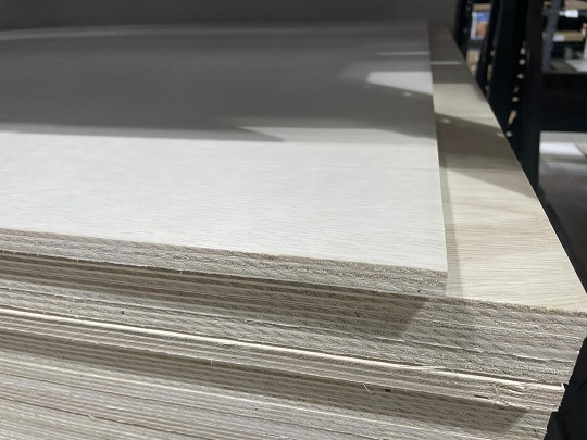
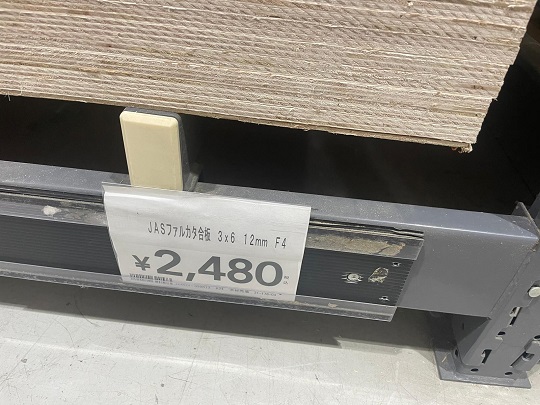
Photos courtesy to Masato Takemura, FabLab Hamamatsu/TAKE Space
6-3. Board Setting
Although it wasn’t so critical for cutting a small piece, if we place the 910mm x 1,820mm board on the CNC router, we have to be careful about the bending of the board. With screws, we have to ensure that the board is layed flat and the end mill could cut precisely. Screws must be placed as near as the tool path. One trick to do this was besides making the toolpath for cutouts, we draw circles with the same diameter as the one for end mill, and drill holes before we proceed to cutting out the components.
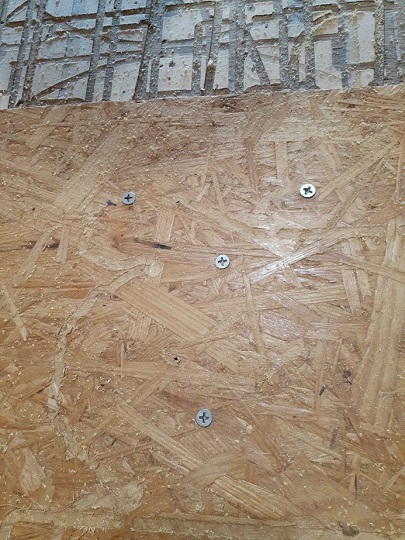
A snapshot in the group assignment
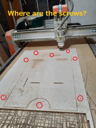
After drilling a few holes around the toolpath of the components, I drove screws to the hole as deep as possible.
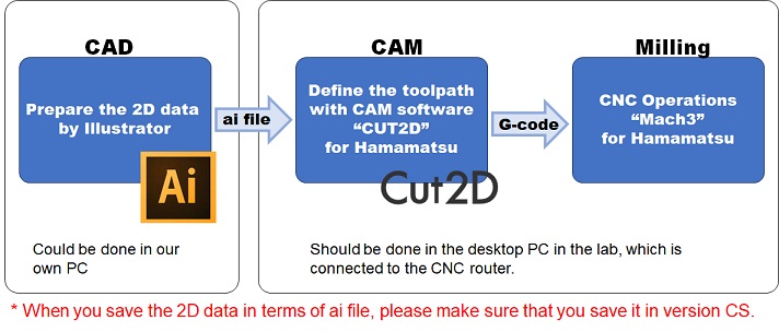
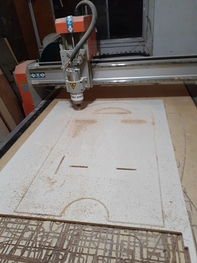
6-4. Cutting
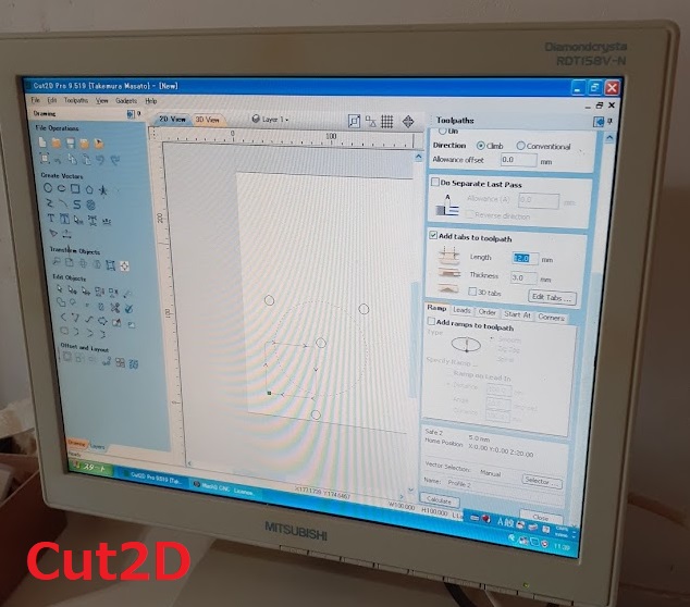
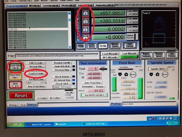
The following image is the description of the whole process. After preparing the 2D data in terms of Ai file, I defined the toolpath with Cut2D CAM software and then proceeded to CNC operations with the router “Mach3”.
CAM settings on the Cut2D was described in details in our Group Assingment website.
Cutting with the CNC router “Mach3” was also documented in our Group Assignment website.
Since the design of my components were so simple, the toolpaths were relatively short and it didn’t take too much time for cutting out all the components.
6-5. Sanding
Sanding is for smoothing the surface and edges of the components. Not much to explain about. Perhaps the second process where we are exposed to a lot of wood dusts. Must wear a face mask, groves and an eye shield.
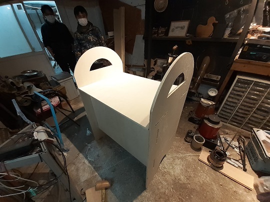
6-7. Assembly, and Sanding Again
After a little sanding, I tried to assemble them and found that some pockets were not thin enough to have the plugs perfectly fit to them. I found that the board thickness was larger than 12mm by 0.1-0.2mm. I should have measured the thickness when I procured the material and reflected it in my parameter on Fusion360. That’s the largest lesson I learned from the local session. I did a patch work by filing the pockets to widen them and the plugs to make them thinner. We were running out of time to take the last train to go back. After a little filing, I tried to assemble them once again. After a few trials, I could reach the point I could assmble them by hammering the joints with a wooden hammer. It was still a bit too tight. But I decided to leave the lab for that night.
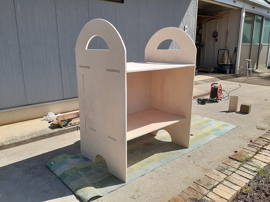
6-8. Follow-up
I carried the whole set of the portable sales stall to my home village that night. On Monday, March 11, I did some more sanding and filing and made it easy enough to assemble them.
7. Reflections
-
Wood-working is probably one of the most needed knowledge and skills for my to live a post-retirement life in a sustainable manner. My house in the home village has already been more than 70 years old and need repair works here and there. However, it has been resided only by my mother at the age of mid 80 and all her children have their own family. Thorough reconstruction may not be a good idea in this situation. I’m feeling that a series of patchwork-type rennovations could be the alternative. Also, both my mother and my wife have separately been asking me if I could design and make the pop-up shop for them to sell the vegetables they harvest in their garden. Therefore, the assignments of the Week 7 meant a lot to me.
-
Actually the large CNC wood router had been one of the critical weaknesses in my skill set. When I was stationed at the FabLab CST in Phuentsholing, Bhutan, I could not show the users how to prepare the design and operate the ShopBot. The assignments of the Week 7 were a great complement to fill my knowledge deficit. This week we visited FabLab Hamamatsu to have hands-on experience in the operations of a CNC router. However, I’m fortunate to have a makerspace in our neighborhood, such as Lifull Fab in Kojimachi, Tokyo, and Colors Factory in Wanouchi-cho, Gifu prefecture. Also, Vuild has been offering on-demand 2D cutting services. I’m feeling I should do more on wood-working.
-
Back to our weekly assignments, it seemed I had designed too big furniture for our requirments of the week. Although I called it “portable”, it was so only when we carry the dissembled parts by car to the target destination. If I just carry them a long distance by train, I may face difficulty in finding a seat to sit down or sometimes I have to bear extra tariffs for large luggage. I haven’t finished painting. Due to the bad weather conditions on Tuesday, March 12, I left the product in my home village. I should go back and finish it, but I need to learn how I should paint it.
-
Also, I should find out the reason why my original design went wrong with interfarence. I started with drawing 2D sketches just on the XY plain and tried to assemble the components after extruding the profiles. But as I browsed the YouTube videos, I learned that there was an alternative approach drawing sketches on all the three plains so that they could form a 3D shape after the extrusion. When I make furniture next time, I should try this approach and add a few documents on this page about my experience.