11. Input devices
Group Assignment
So, in our group task we used distance sensors, one of them is the HC-SR04 ultrasonic sensor, the other is the Sharp GP2Y0A21YK0F infrared sensor. We tested analog and digital signals.
Ultrasonic sensor HC-SR04
We measured ultrasonic signals using an oscilloscope.
Briefly about the important
We wrote code to calculate distance by converting the time it takes to transmit and receive sound.
 distance = duration * 0.034 / 2
Duration * 0.034 converts duration to centimeters. 0.034 - speed of sound in air 0.034 cm/µs.
The result is then divided by 2 because the beep takes time to go back and forth.
distance = duration * 0.034 / 2
Duration * 0.034 converts duration to centimeters. 0.034 - speed of sound in air 0.034 cm/µs.
The result is then divided by 2 because the beep takes time to go back and forth.
Infrared sensor Sharp GP2Y0A21YK0F
So, using a meter and white cardboard, we measured the distance from the sensor every 10 cm and entered the value into the table.Which, using comparison, converted these values into an equation that could be used to write code.

It turned out that the infrared sensor has a minimum distance of approximately 20 cm. We achieved approximately the same result, but there was an deflection of three centimeters.
Individual Assignment
So this week we got to test out the input devices. And since I will be using a lot of capacitive sensors in my final project, this week I decided to make a step response sensor. So I started by studying our lecture with Neil. And I did a little research on RC circuits and eventually found out what is the reason for the resistor in this circuit and understood the whole process of capacitive touching.
Research
 So, I discovered that a resistor in RC circuits is used to prevent the initial current surge. But for step responding - big resistance important to respond the big distance
Step Response
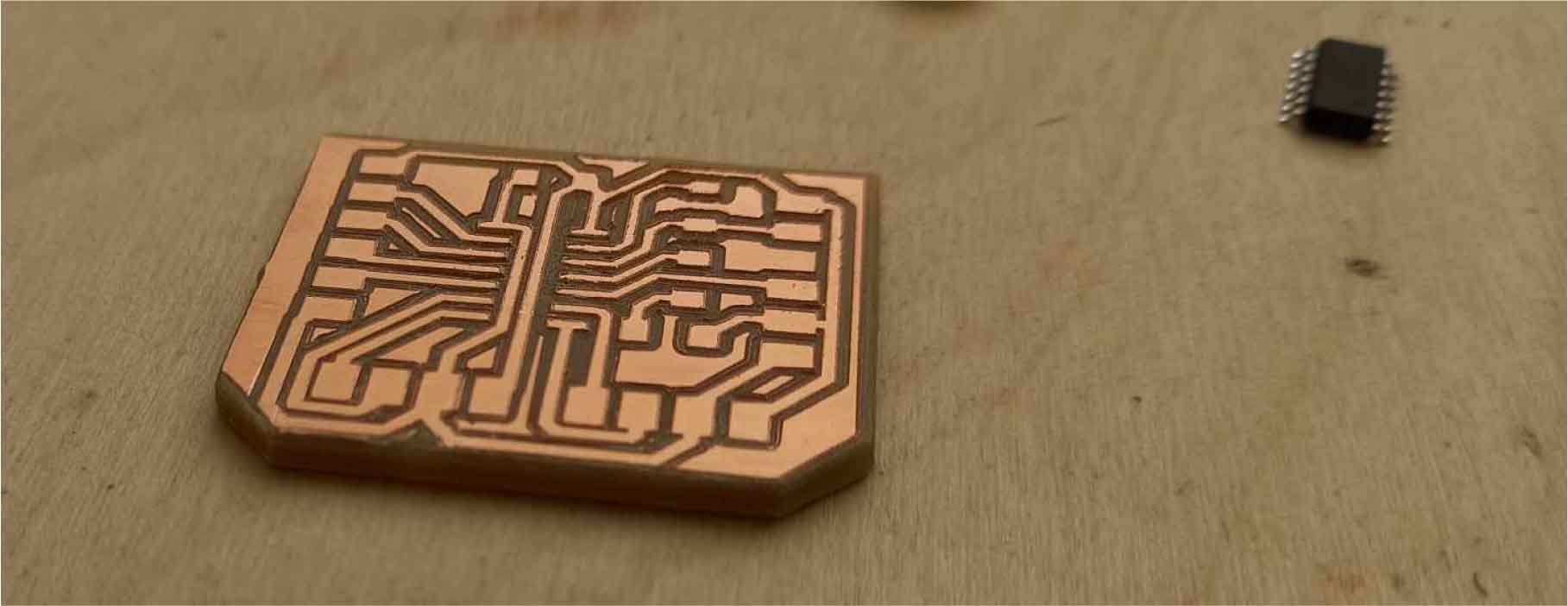
And so after research I started designing my board using ATtiny 1614.

So this is my schematics and board
- On this board I designed 3 pins for the updi converter for programming .
- Also made 2 4-pin ports for connecting I2C and UART.
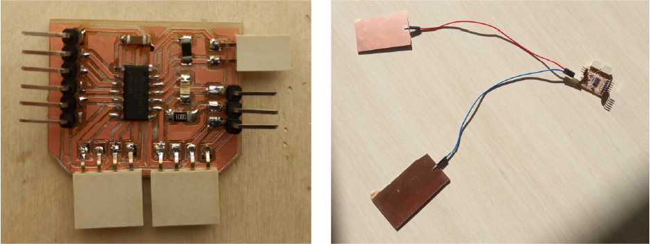
- I also added two pins for the capacitor plates, one of them is connected to ground, the other to pins 10, 9 via a 1 M Ohm resistor as Neil advised.
- I also added led with his resistor connected some free pin as integrated output for test
- Some free pins.
Then I make 2 separate plates with wires.
Problems
I ended up trying to program it using Neil’s code,
- but it turns out it was written in assembly language using Python or using another microcontrollers and I couldn’t find the code I needed.
- Then I also realized that my serial monitor will not work with ATtiny directly.
Solution
- And that why I decided use lcd monitor or usb cable to connect my board with serial monitor.
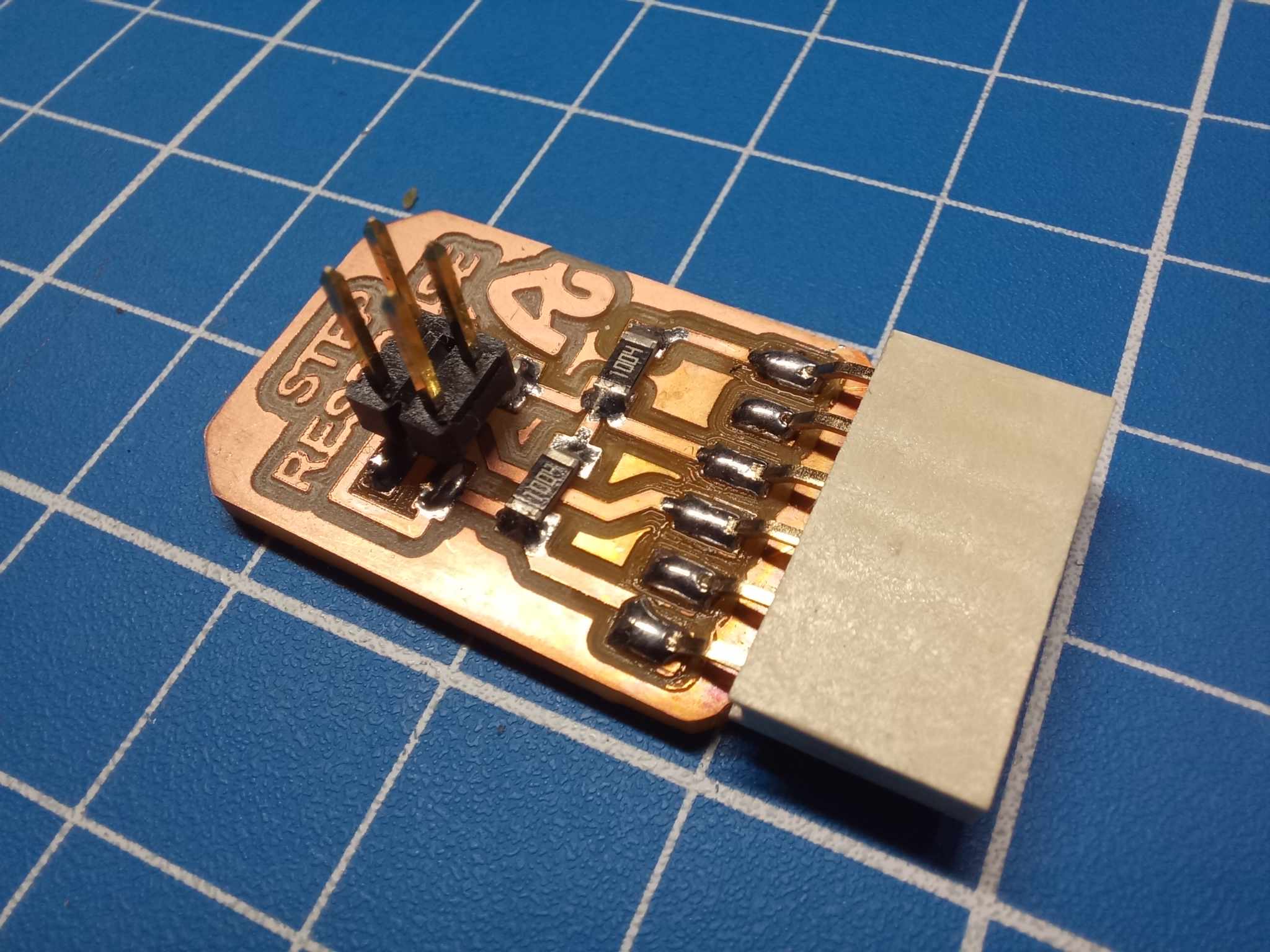
- I also decided to use Adrian’s Step Response board without modifications, because I didn’t have enough time then
Second attempt
I made a board and tried it again according to Adrian’s instructions.
//tx_rx03 Robert Hart Mar 2019.
//https://roberthart56.github.io/SCFAB/SC_lab/Sensors/tx_rx_sensors/index.html
//Modified by Adrián Torres Omaña
//Fab Academy 2021
//Step Response TX, RX
//Adrianino
//ATtiny1614
// Program to use transmit-receive across space between two conductors.
// One conductor attached to digital pin, another to analog pin.
//
// This program has a function "tx_rx() which returns the value in a long integer.
//
// Optionally, two resistors (1 MOhm or greater) can be placed between 5V and GND, with
// the signal connected between them so that the steady-state voltage is 2.5 Volts.
//
// Signal varies with electric field coupling between conductors, and can
// be used to measure many things related to position, overlap, and intervening material
// between the two conductors.
//
long result; //variable for the result of the tx_rx measurement.
int analog_pin = 1; // PA5 of the ATtiny1614
int tx_pin = 2; // PA6 of the ATtiny1614
void setup() {
pinMode(tx_pin,OUTPUT); //Pin 2 provides the voltage step
Serial.begin(115200);
}
long tx_rx(){ //Function to execute rx_tx algorithm and return a value
//that depends on coupling of two electrodes.
//Value returned is a long integer.
int read_high;
int read_low;
int diff;
long int sum;
int N_samples = 100; //Number of samples to take. Larger number slows it down, but reduces scatter.
sum = 0;
for (int i = 0; i < N_samples; i++){
digitalWrite(tx_pin,HIGH); //Step the voltage high on conductor 1.
read_high = analogRead(analog_pin); //Measure response of conductor 2.
delayMicroseconds(100); //Delay to reach steady state.
digitalWrite(tx_pin,LOW); //Step the voltage to zero on conductor 1.
read_low = analogRead(analog_pin); //Measure response of conductor 2.
diff = read_high - read_low; //desired answer is the difference between high and low.
sum += diff; //Sums up N_samples of these measurements.
}
return sum;
} //End of tx_rx function.
void loop() {
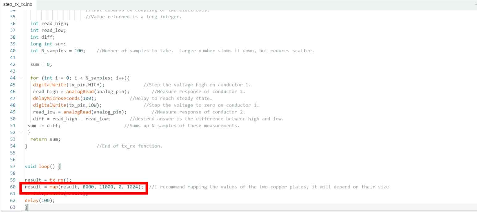
result = tx_rx();
result = map(result, 8000, 11000, 0, 1024); //I recommend mapping the values of the two copper plates, it will depend on their size
Serial.println(result);
delay(100);
}
Uploaded the code to the board and connected an exposed USB-B cable to the board to see the result. Connected the terminals of VSC to VSC, GND to GND, Tx to RX and RX to Tx.
Sensor calibration
Then I calibrate my sensor changing this values.
It is important to note that My sensors are affected by both the size of the plates and the distance between them.
- And so I fixed the plates.
- Then i deleted mapping code and uploaded it.for getting origin result.
- I then noted the value of my sensor in natural environment and compared those values with 0.
- Then I did the same thing, only moving the value up maximally with the touch of my hand.
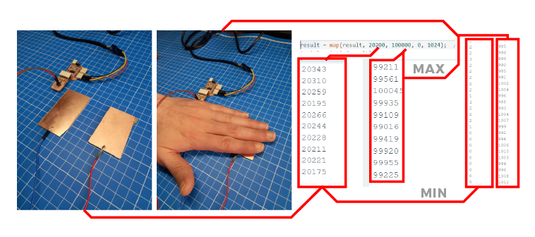
This way I got the minimum and maximum values that I need. Naturally my sensor is very sensitive and could use more, but I don’t need it.
In this way you can calibrate the sensor for every occasion
After that I checked the readings on the serial monitor as well as on the Serial plotter and everything worked.
Procesing
Then I rendered it using Adrian’s code in Processing.
//Fab Academy 2021 - Fab Lab León
//Step Response
//Adrianino
//ATtiny1614

import processing.serial.*;

float sensorValue; //variable for the serial data
Serial myPort;

void setup() {  //as dynamic/setup function called initially, only once
size(1024, 200);// is the window (1024=sensor max. value)
//replace the port String with the port where your Arduino is connected
//myPort = new Serial(this, "/dev/tty.wchusbserial1450", 115200);
myPort = new Serial(this, "COM4", 115200); // serial port
background(255);  //set background white

}

void draw() {  //draw function loops

noStroke(); // outline
fill(255,0,0,20); // color inside
rect(0, 0, sensorValue, height); //position and size

fill(255,70);
rect(sensorValue, 0, width-sensorValue, height);

println(sensorValue);
fill(0,0,0);// these are the colors inside
text(sensorValue + " " , sensorValue, height/2);
textSize(32);

}

void serialEvent(Serial myPort) { // sketch read the serial data
String inString = myPort.readStringUntil('\n');
if (inString != null) {
    inString = trim(inString);
    float[] values = float(split(inString, ","));
    if (values.length >=1) {
    sensorValue = values[0]; //first value in the list
    }
}
}
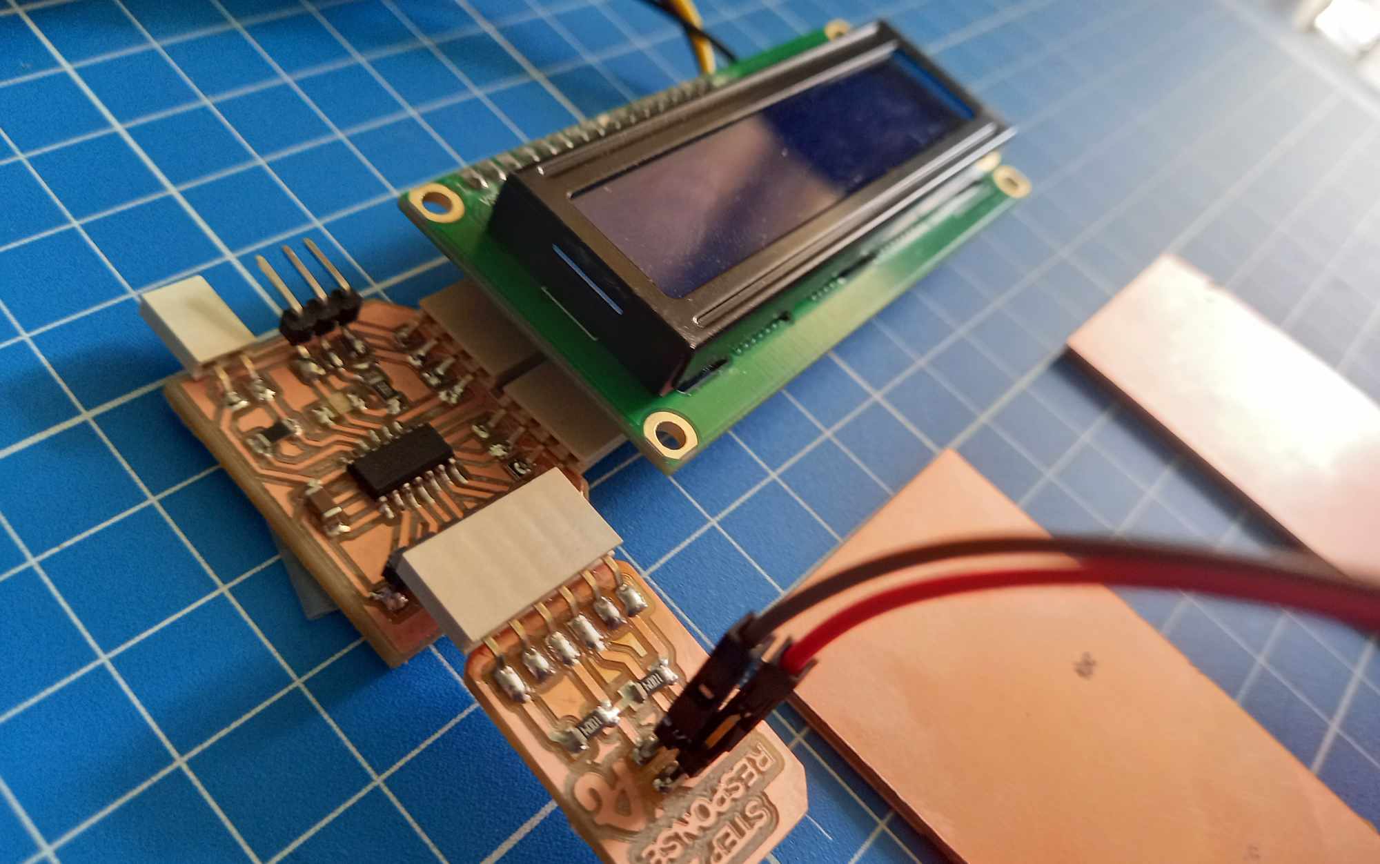
Displaying on the LCD
In the end, I connected an LCD display to the board, slightly changing the code for convenience.
#include <Wire.h>
#include <LiquidCrystal_I2C.h>
long result;   //variable for the result of the tx_rx measurement.
int analog_pin = 1; //  PA5 of the ATtiny1614
int tx_pin = 2;  //     PA6 of the ATtiny1614
LiquidCrystal_I2C lcd( 0x27, 16 , 2 );
void setup() {
pinMode(tx_pin,OUTPUT);      //Pin 2 provides the voltage step

lcd.init();
lcd.setBacklight(255); // turn on backlight
}

long tx_rx(){         //Function to execute rx_tx algorithm and return a value
                    //that depends on coupling of two electrodes.
                    //Value returned is a long integer.
int read_high;
int read_low;
int diff;
long int sum;
int N_samples = 100;    //Number of samples to take.  Larger number slows it down, but reduces scatter.

sum = 0;

for (int i = 0; i < N_samples; i++){
digitalWrite(tx_pin,HIGH);              //Step the voltage high on conductor 1.
read_high = analogRead(analog_pin);        //Measure response of conductor 2.
delayMicroseconds(100);            //Delay to reach steady state.
digitalWrite(tx_pin,LOW);               //Step the voltage to zero on conductor 1.
read_low = analogRead(analog_pin);         //Measure response of conductor 2.
diff = read_high - read_low;       //desired answer is the difference between high and low.
sum += diff;                       //Sums up N_samples of these measurements.
}
return sum;
}                         //End of tx_rx function.

void loop() {

result = tx_rx();
result = map(result, 19700, 65000, 0, 1024);  //I recommend mapping the values of the two copper plates, it will depend on their size
lcd.setCursor(0, 0);
lcd.clear();
lcd.print(result);
delay(100);

}
Sensores
So what we have after testing. I made from this device to Touch , Proximity, Pressure & Capacity Sensors.
Conclusion
So this week I tested the step response sensor and at first I lost a lot of time because I wanted to develop it myself and I did a lot of research about capacitive touch sensors but I had problems with the coding and the first attempt failed. Well what can I say about this sensor, it is great, it can be used almost anywhere, it reads everything from touch to capacity. It can also be used as a dimmer or proximity sensor or pressure sensor, and I also found that it reads not only the thickness of objects but also texture, for example it responds to water much better than paper. The reason for this is that water is electrically conductive. And the most important advantages - This is that it can distinguish a person from an object in the sense that when a person approaches, their indicators decrease, and when an uncharged object approaches, they increase. And with this sensor you can read touch or proximity coordinates like on smartphones, I haven’t tested it now but in my final project I want to use this feature.
Source files
Click for downloading
Input zip-all files