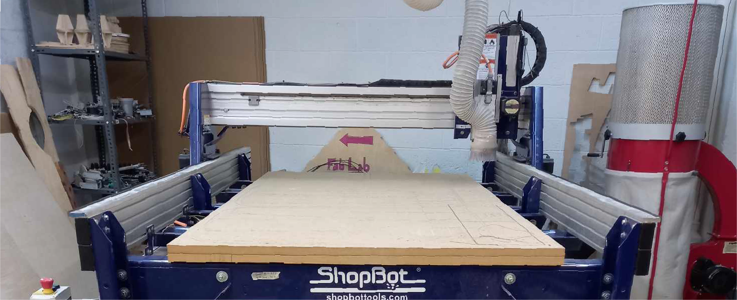
7. Computer controlled machining
It’s finally time to do something big and I have a lot of plans for this week.
So during the week of design and laser cutting I have already carried out several experiments and now I will develop the idea.
Group assignment:
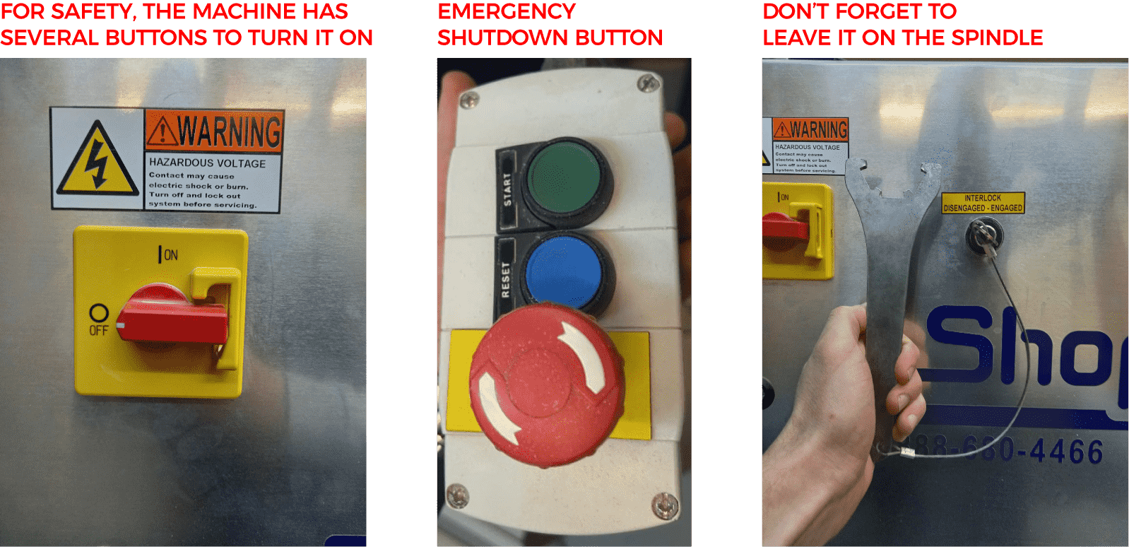
During the group assignment, I learned a lot about safety and using a computer controlled machine.
Safety I learned how important it is to practice safety when operating the machine. This includes inspecting equipment before use, wearing protective clothing and eyewear, and ensuring the work area is clean and safe.
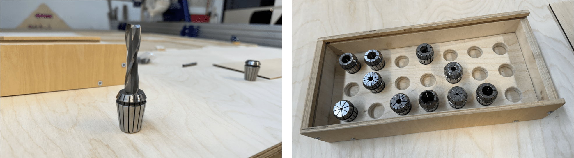
Using the machine I learned how to set up the machine, select the right tools and cutting parameters. I also learned how important it is to position the material correctly on the machine bed to achieve the best results. We assessed the machine’s capabilities and its accuracy. I learned how important it is to consider machine performance when designing parts to ensure they assemble and function correctly.
Testing: Of course, an important part of our work this week was testing the machine’s kerf accuracy. We conducted a series of experiments to determine how accurately the machine could cut materials and how the cut affected the final size of the parts. In testing, we found that the kerf, or width of the cut, can have a significant effect on the size of the parts being cut. This is especially important when designing connections and assemblies where high precision is required. Understanding the kerf allowed us to adjust our designs to compensate for the width of the kerf and ensure proper fit and assembly of parts.

Individual assignment
Planning
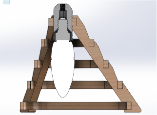
My project will be in two parts.
| 1.Final Project | 2.Lamp |
|---|---|
| The first is a perforated sheet for my final project. | The second is a large vertical and horizontal lampshade made from scraps from my final project. |
| So I’ve already designed the base in previous weeks and now I need to add holes for the magnets and change the dimensions to be more efficient. | In previous weeks I’ve already designed the lamp shade but it made with cardboard and now I need to change parameters and change the geometry to make it longer. |
Design Process
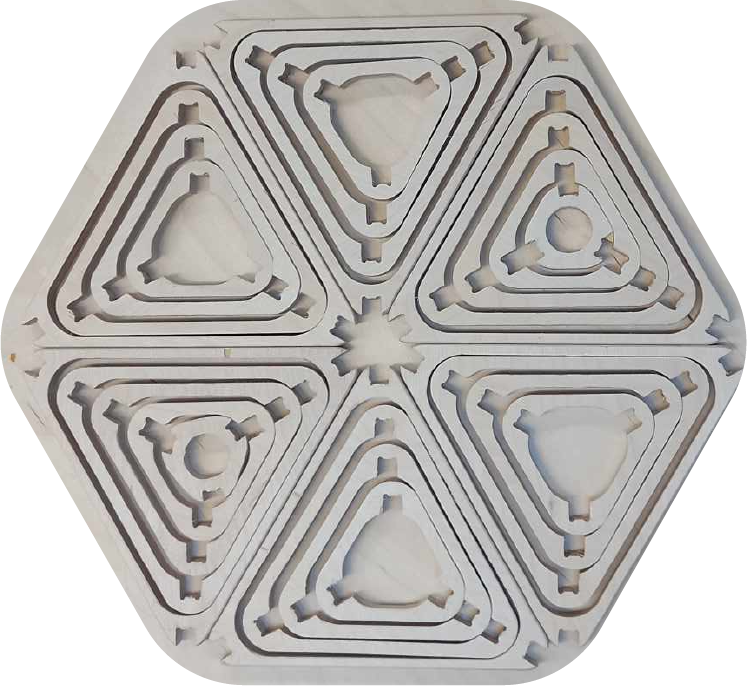
First of all I changed the number of cells.
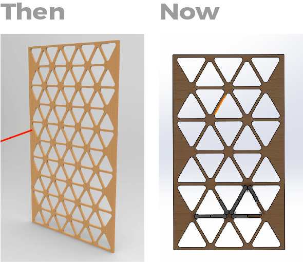
Than i added holes for magnets 7x3.
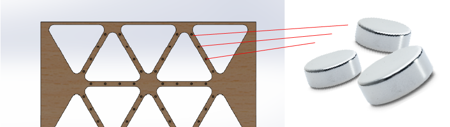
So before I continue I want to point out that I intended to use the waste from my Final project into something useful and so on the week of the Computer controlled cutting I designed a parametric model of a lamp which was just a prototype and this week I want to change its model a little and make it from plywood.
And I started changing the parameters of the lamp to 12 mm thick plywood.I also changed the tool diameter .
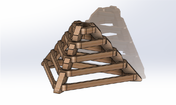
After that I started experimenting with the assembly and this is what I came up with..
I also designed several types of frames for different sizes.
Single one
I also made some renders for clarity and this is what I came up with.
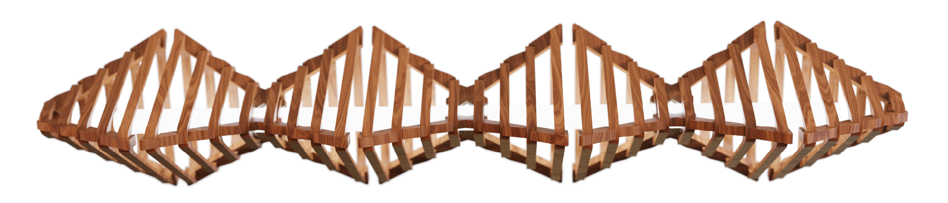
After that I made an assembly for cnc machine
Cutting Process
Let me start by saying that it turned out that the cutting I had planned took a very long time, and since we have limited time, I changed the layout a little.
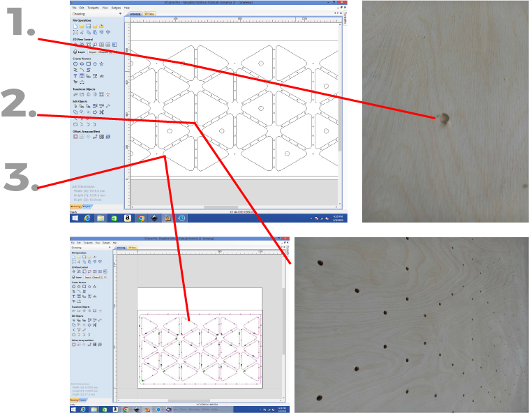
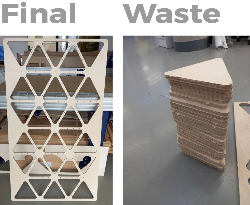
I ended up with a piece of my final project and a bunch of scraps.
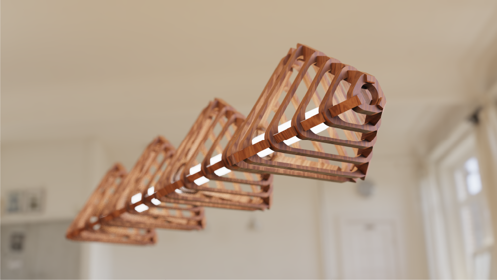
The Lamp
And here’s the problem:
How do I use these scraps to get the desired result?

Creating a template
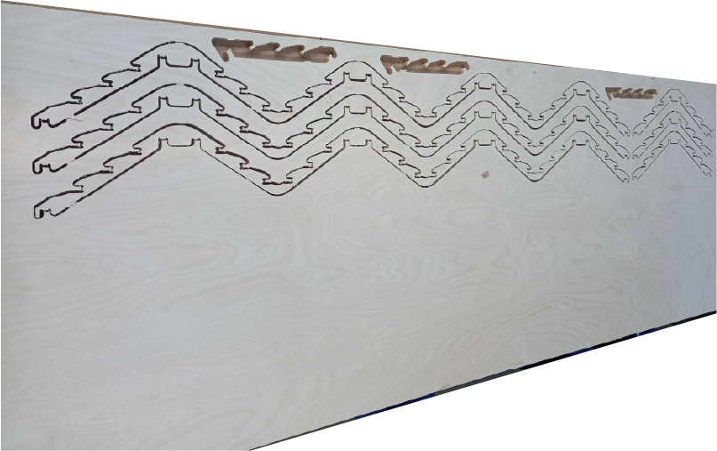
Since I needed to cut out each triangle separately, I decided to use a template for positioning. And for this I took plywood 6 mm thick and fixed it in the upper left corner for convenience .And also I cleaned triangles of burrs.
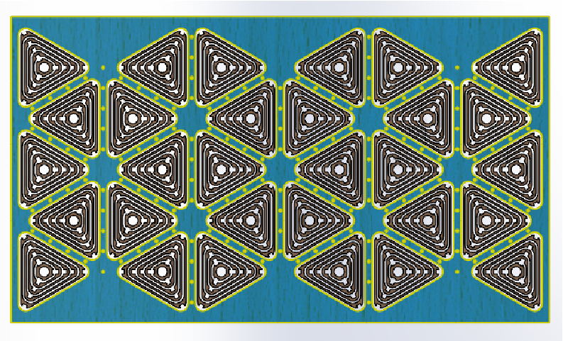
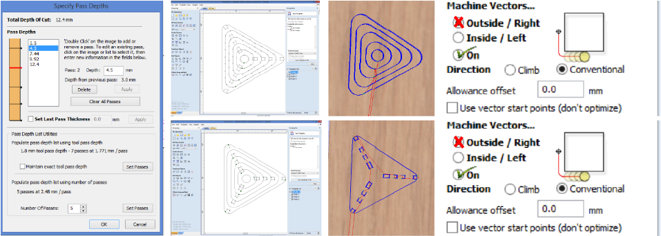
And in the V Carve program I generated a g-code with 3 subdivisions
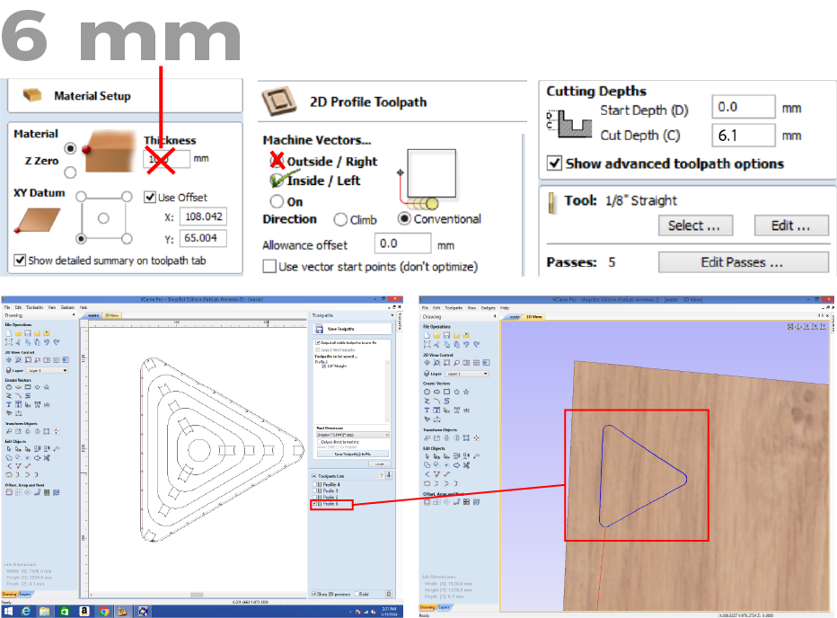
First I set the thickness of the material and change the cutting depth, and also select the type of cut. I first used the outer curve to cut out the stencil. for this I use a 1/8 cutter and select the inside option to create a path.
Since our cutter is round and it cannot directly cut “Inside Corner” I need to add dogbones. Based on past experience, I realized that I cannot simply export the curves I need from 3D models, because the machine will take a long time and the result will not be what I need.So I decided to draw the curves myself for the machine to cut ON the line , and I also added the dog bones manualy.
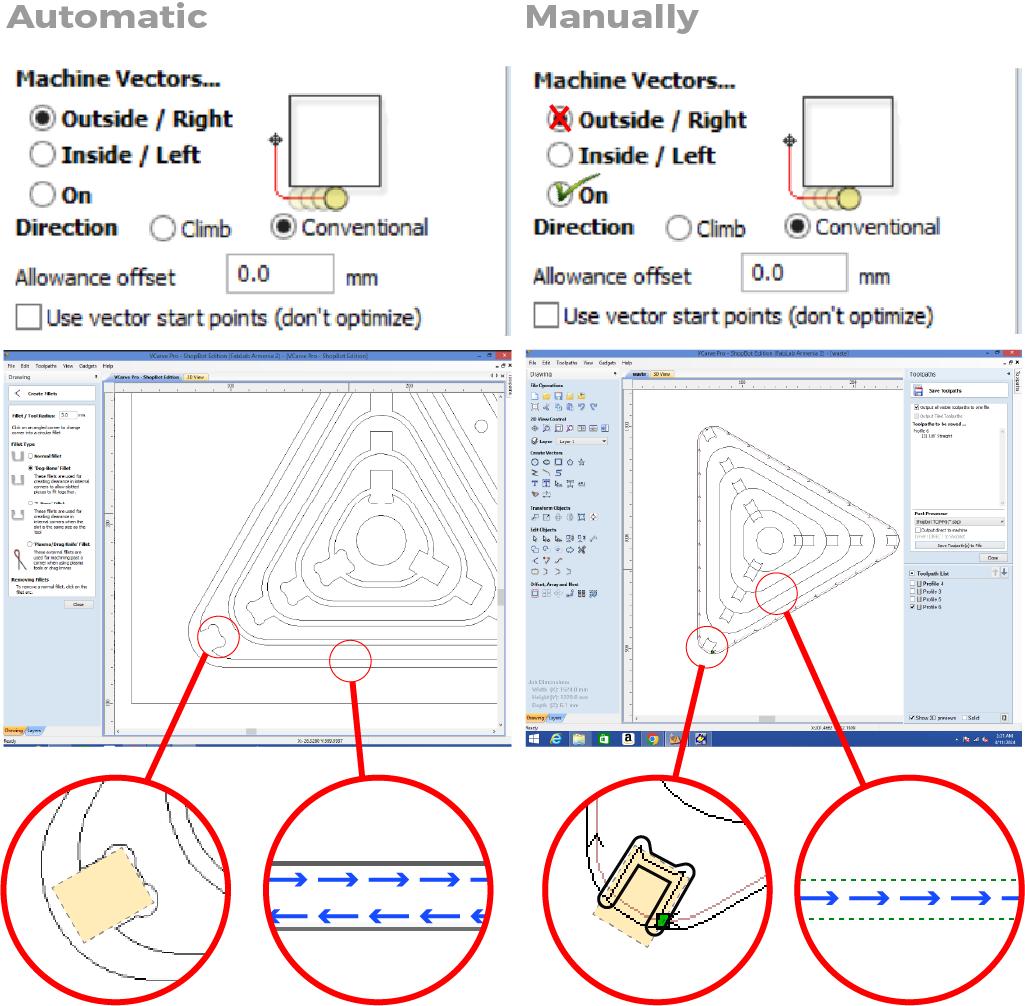
| On the left with blue lines you see the path of the cutter with Inside settings. | On the right with the setting ON there is one blue one path |
|---|---|
And this means that with such settings the machine will cut along one line and gain twice the time
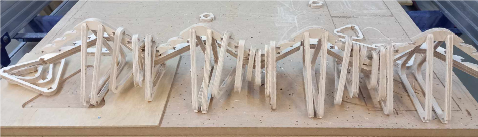
Cutting of workpieces
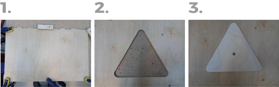
And so cutting I did it in two stages, first I cut out the squares for the connections and then in the second stage I cut out the outlines.
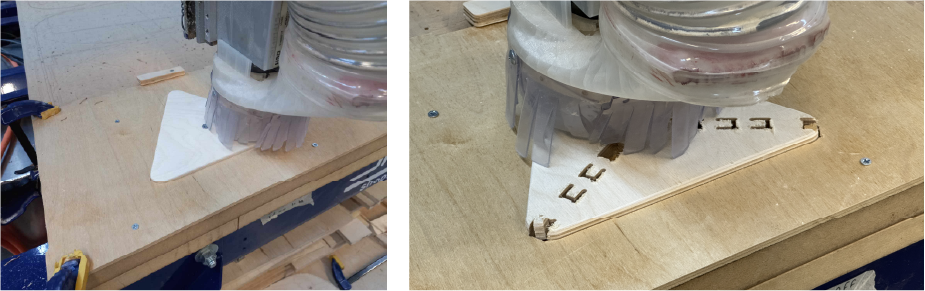

 After cutting, I processed the parts a little with sandpaper and a drill
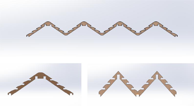
Frame
I cut out the frame parts separately

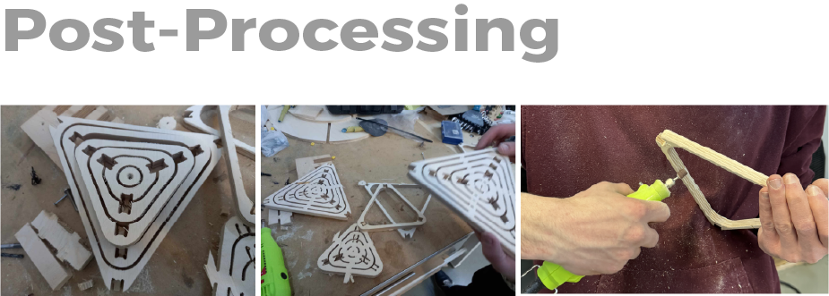
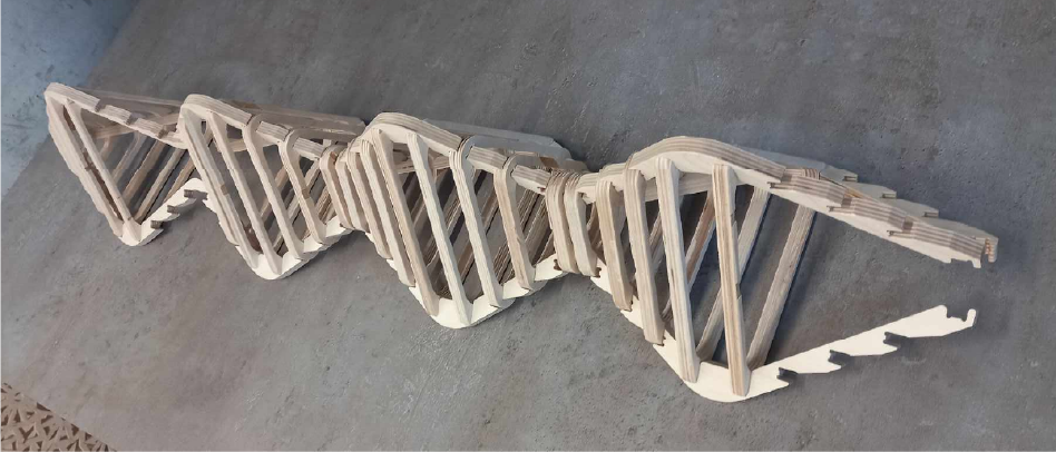
Assembly
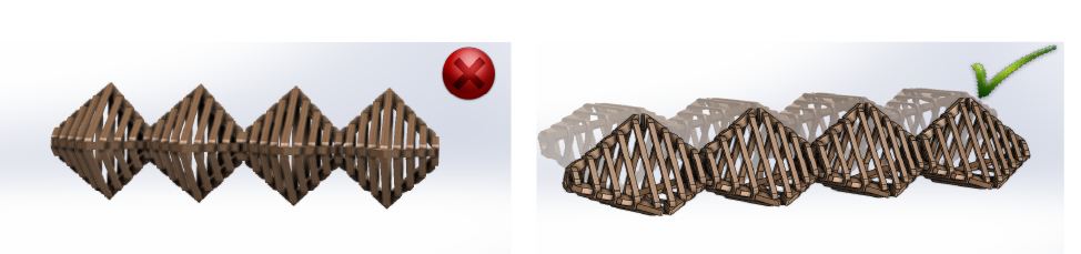
And so my designed joints worked perfectly but I didn’t consider that fact that I have to assembly the wery long lamp that will have a lot of small parts.
And it turned out that it was impossible to do.
But I found out what the problem is and in the future I can slightly change my design for assembling parts and achieve the desired result
Conclusion
Despite the problems it looks very good and I’m happy with my work This week I took on the challenge of making not only something big, but also something very detailed, meaning my intended project had a lot of parts and they were very fragile. It may have been a mistake, but for this reason I can to say that it gave me much more experience than if I did something just big. It was very difficult in fact. And in my project, in addition to the difficulties, I encountered such a problem that cutting my file took me much more time and so I decided to simplify the task a little and make each element separately. And this is what happened: I had to cut each triangle separately and for this reason I had to turn the machine on and off many times and for this reason I got used to it and gained much more experience, for example, how the machine works and in what order the operations need to be done for safety and etc . And also, since I had to cut all the parts separately at a specific place so that the axles would not mix, I learned how to mount the parts separately at a specific place. I had problems with assembly because my product was very complex and there were many small parts in it, but in the future I will fix this error and figure out how to collect such things in a simpler way.
-
Source files
Click for downloading