5. 3D Scanning and printing
It’s finally 3D printing week. I was really looking forward to this because I have a lot of experience in this matter. I have my own 3D pinter, but I would like to do something unique that I haven’t done before.
Group assignment
So this is a group assignment that was done in Fablab so you can read about it at this link. Group assignment
Our laboratory has several 3D printers from Creality:
These 3 printers use a standard Cartesian motion system
| Characteristics | Ender 3 | Ender 3 Pro | Ender 3 V2 |
|---|---|---|---|
| Print area: | 220 x 220 x 250 mm | 220 x 220 x 250 mm | 220 x 220 x 250 mm |
| Maximum table temperature: | 110°C | 110°C | 100°C |
| Maximum hotend temperature: | 255°C | 255°C | 255°C |
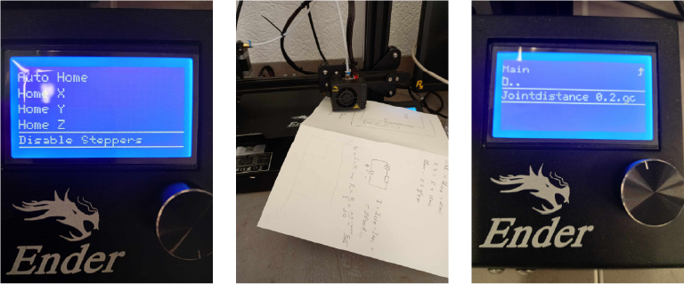
Printer accuracy test
We also conducted a test to determine the optimal distance between the two walls to prevent filament sticking during printing and ensure that the walls are formed separately.
We decided to run this test on the following printers:

Ender 3 PRO - we see that the valve opened in cases of 0.5mm and 0.4mm, that is, with this printer you can work with gaps starting from 0.4mm.
Ender 3 V2 - in this case we see that the valve opened by 0.5mm, 0.4mm and 0.3mm, that is, with this printer you can work with gaps starting from 0.3mm.
Creality CR-30 did’nt give any results.
We also have the CR-30, which differs in that it prints at an angle of 45 degrees and has a movable platform for printing long objects. We decided to test our printers in several ways.
| Print area | Maximum table temperature | Maximum hotend temperature |
|---|---|---|
| 200 x 170 x unlimited length | 100°C | 240°C |
Special features
- Unlimited Print Length - Thanks to the movable platform, this printer can print objects of any length, which is especially useful for making long parts.
- 45 Degree Angle Printing - The platform is tilted at 45 degrees, allowing you to print models with less support and make more efficient use of space.
- Conveyor Belt The platform’s moving belt automatically moves finished products, facilitating mass production and continuous printing.
- Compact Design - Despite its unique capabilities, the printer has a relatively compact size, allowing it to be used in confined spaces.
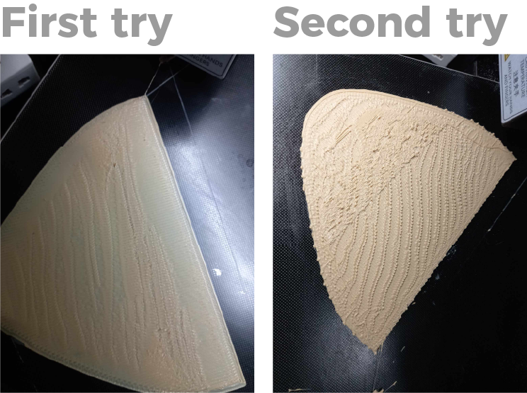
For this printer we used Creality Slicer. We made two printing attempts. However, print quality was equally poor for both attempts.

Second group assignment
Well, besides this group assignment, Ellen and I decided to do something else. So let’s start with a group task. Elen and I agreed to do something very big together because my printer has a large working area. But I have never done anything like that.
I would also like to complicate the task because there are practically no problems with PLA and PET G.
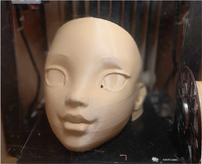
And so we decided to choose ABS plastic because it is very capricious, has a lot of shrinkage and this is very problematic for large parts that we want to print. So, we started work by designing the parts, the part turned out to be not a part, we wanted to make a mask in the shape of a doll. More information about modeling and sculpting can be found on Elen’s website.
Slicing
After modeling, we opened the UltiMaker Cura slicer and started selecting settings for Anycubic Mega X.
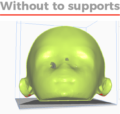
During the process, it turned out that in some places needed support. But this added a lot of time and wasted a lot of plastic, so we decided to remove these points.
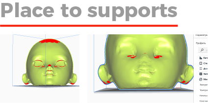
Except that Elen changed the geometry to remove supports I set the angle for support to 65 I already knew this is an acceptable number and also I used blocking for support in some places.
Printing
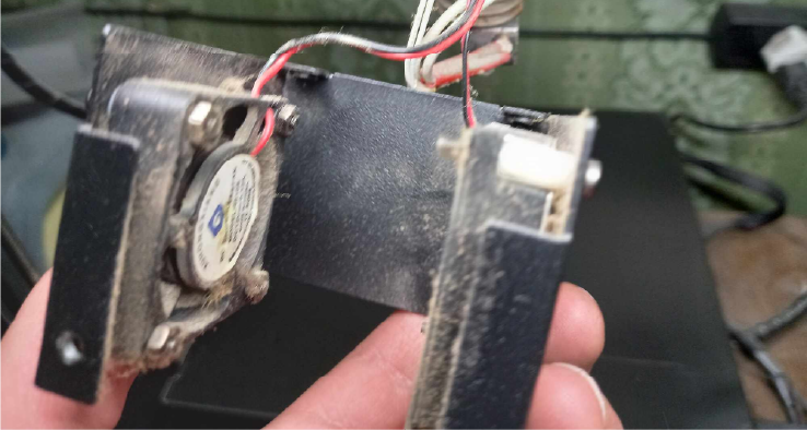
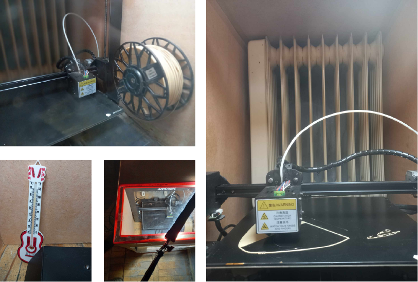
So, I haven’t used the printer for a month and it has accumulated dust and dirt.
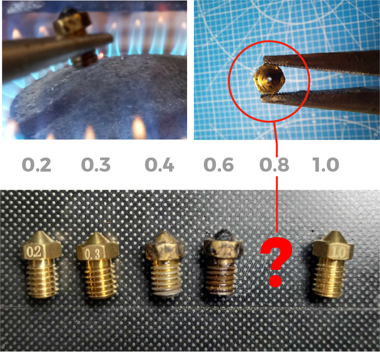
I cleaned the printer and cleaned the nozzle that I want to use.
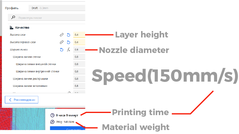
I decided to use a 0.8 mm nozzle to save time
Nozzle installation
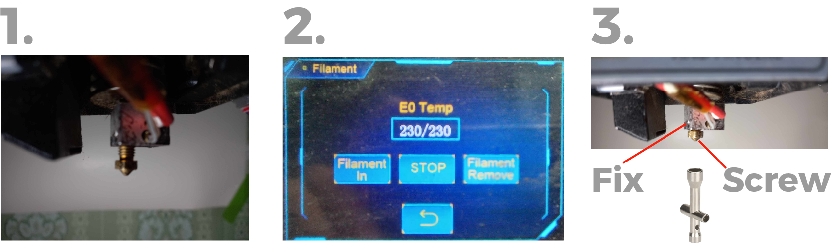
Step 1. I install it but don’t screw it in completely
Step 2. Turn on hotend heating
Step 3. Then hold the cap and completely unscrew the nozzle
Desk height and level adjustment

I also used adhesive spray because I knew that ABS has problems sticking to the table.

First fail
So I started printing but it turned out that something was wrong and at first I thought that there was a problem with the surface and started to fix leveling. But the second attempt was still unsuccessful.
It turned out that the problem was with speed. I really wanted my printer to be faster, but unfortunately it is beyond its capabilities

I changed the speed to 80mm/s and installed it again.

And that’s what happened

And the warping problem big as model. Due to shrinkage, all the corners began to deform and eventually the model came unstuck from the table
Challenge accepted
I wasn’t upset and started thinking about how to treat the problem.
And to do this I decided to do three things:
1. I need to solve the adhesion problem.
2. So that the heat from the table works more efficiently.
3. My table only heats 90° and for this I need an additional heater.
1. Adhesion problem
For adhesion I used ABS juice, mixed the waste with acetone and applied it to the bed surface.
2. Thermal chamber
So we made a box out of cardboard and put the heater in it.

I got really carried away and made a door, a window, and installed a light.

Some other feils.

Last Chance
This time I coated the table with glue, as much as possible, and printed it again.
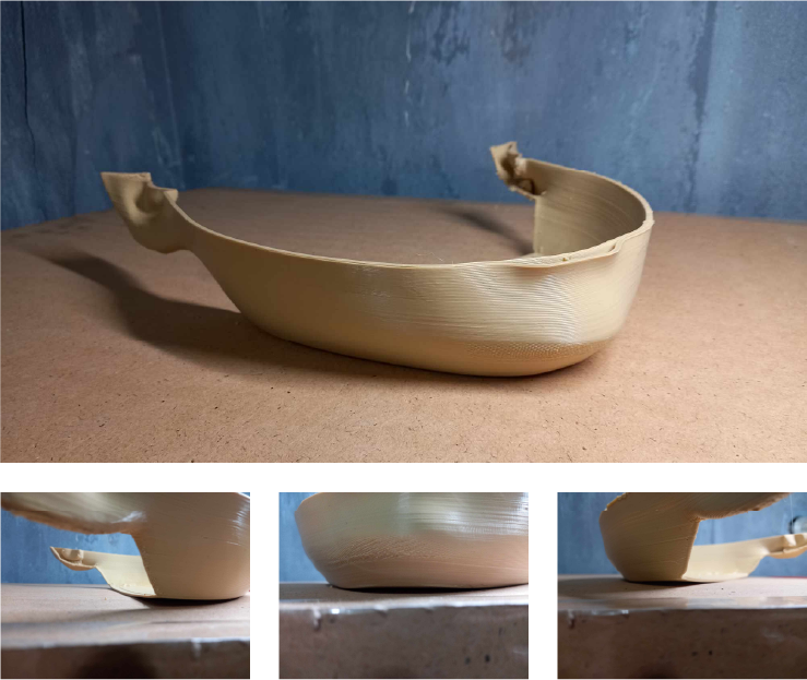
And I finally have result.
Disadvantages
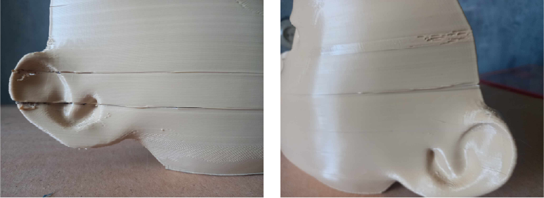
This time I did better. Although one piece came off the table during printing, I reattached it using ABS juice.Then delaminations appeared in some places and the model began to crack, so I stopped printing and glued.after that, 2 hours later, when another 5 cm was printed, the model appeared again with delamnations, but it did not crack.
The main problem
With ABS plastic is high shrinkage and therefore other problems arise.
- Warping
The Reason
So this problem manifests itself when the upper layers begin to cool and the lower ones remain hot and since our table is heated, tension appears in the layers which leads to warping.
Solution - So this problem appears in the first layer and for this we need to use a good adhesive .
-
And since the deformation occurs from small to large, I mean that the shrinkage goes to the center, where the mass is greater. Parts with corners are at great risk because they have an uneven cross-sectional area and the corners are very small and subject to very large deformations.
During the design process we must minimize the corners or add a perfectly round shaped rafting. -
Delamination
The Reason
So this problem manifests itself most on large and tall parts. The problem itself arises for the same reason of shrinkage, but when we solve the problem of attaching to the table, the layers must go somewhere and they seem to decide to separate from each other.
Solution
Here’s just one solution you can print in thermal chambers, preferably in an active thermal chamber, which maintains a temperature closer to 90°.
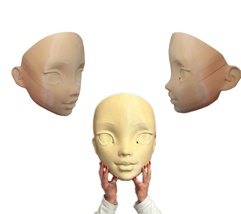
Conclusion
I consider this experiment successful, because I managed to finish printing despite the fact that ABS is very capricious and in general my printer is not designed for this. For abs, the required table temperature is 110-130 degrees, but I printed at 90, but besides this, even good printers cannot cope with such sizes. Despite the result, I achieved this in very complex ways, and 3D printers are not here to torture us I will not print large ABS parts on this 3D printer. Pet g or Pla are suitable for these tasks better. As far as nozzles go, I used a 0.8 nozzle but got a great finish and think I could have used larger nozzles.
Individual assignment:
As you already know, I decided to do my final project gradually according to the tasks of the week.
And so this week I decided to model my vision for the final project and make angle adjustment joints for it.
-
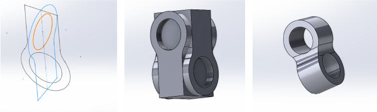
1. Connections
 The first thing I did was the connection details. These pieces will connect my devices and act as decorative lighting.
 -
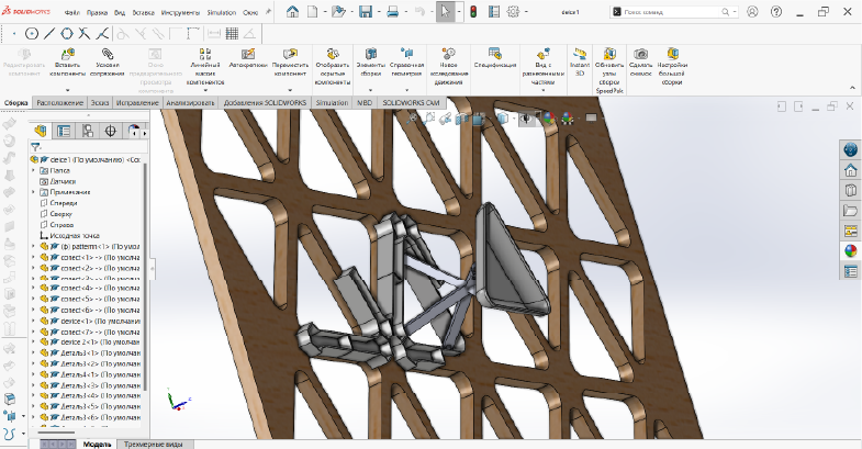
2. Assembly
 Then I made the assembly with a wooden base which I developed during design week.
 -
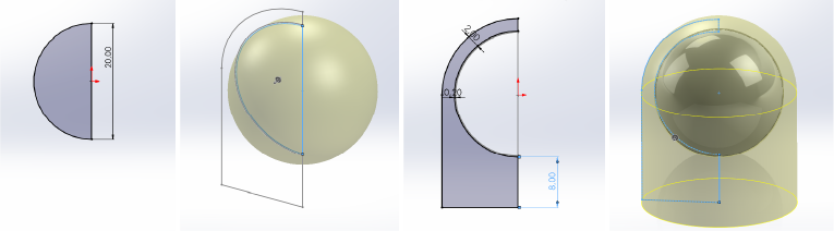
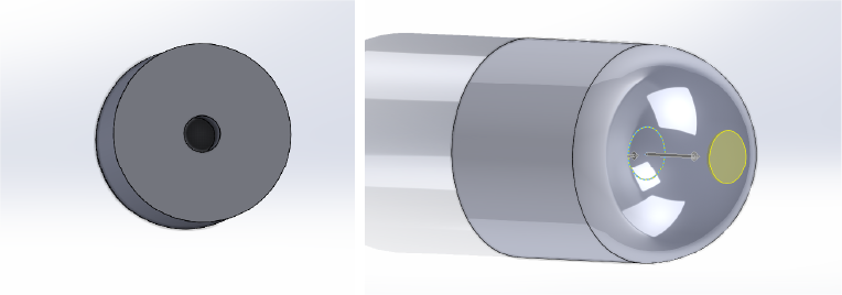
3. device
 And I created the main device form.It is a basic shape that can be a light source, a speaker, a display, or anything else for my final project.
 -
4. Possible joints
I wanted to do something like that Source of inspiration but I think it’s so complicated and unuseful for my final project and I decided to do something else.
-
5. Real one
-
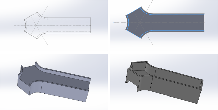
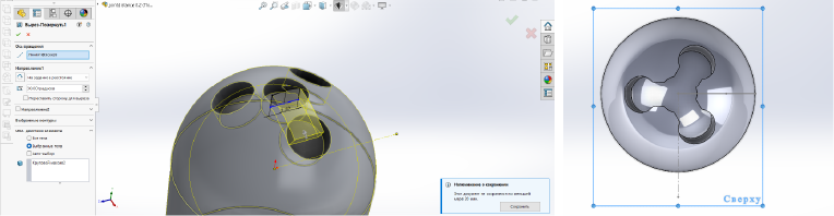
So I created a new part and drew two sketches: one for the shell, the other for the inner sphere.using by revolved boss I transformed the sketch into a body.
-
Then I create holes for future screws
-
And using a circular array, I first cloned the hole at 30 degrees and then in the same way cloned the last hole at 120 degrees in the Z axis 3 times.

-
I then create the paths by first creating a new sketch and using a revolved cut to connect the holes.
-
Then I added some fillets to smooth it out.

-
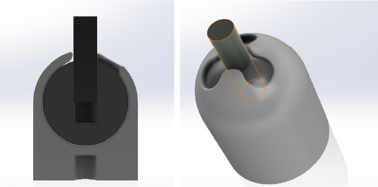
So it will be a ball joint with positioning without assembly.
-
And finally I added some fillets so I could print them without support.

3D Printing
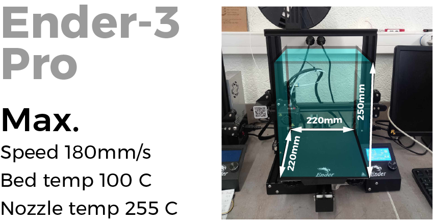
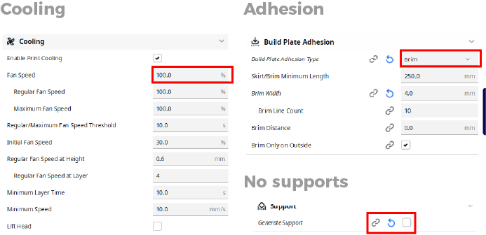
For this task I used Fablab printers, namely Ender-3 Pro and used a 0.4 nozzle. with a layer thickness of 0.2 thicknes of wall I seted 3mm. and I also use the adaptive layers option for smoother surfaces.
This printer is smaller than mine, but has good performance because the bed can heat up to 100°. and it’s faster than my printer.
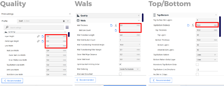

 Other settings
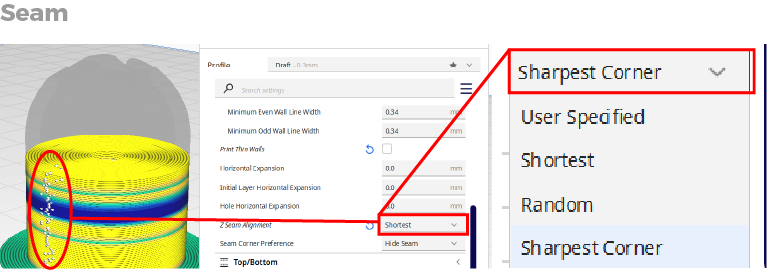 I don’t have any corners so I put the shortest one
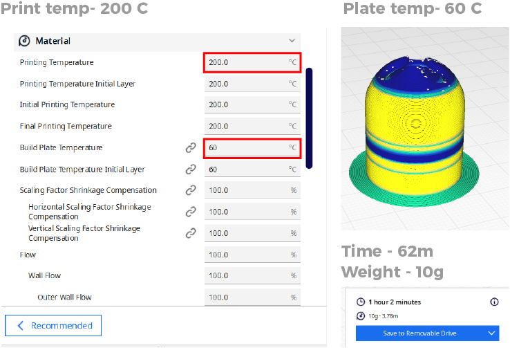 For the print i will use pla plastic and that why I set the bed temp 60 and the hotend temp was 200
-
Attempts:
First I set the bed level and start to print.

-
First unsuccessful attempt:
The first attempt was not very successful, since I set the distance between the parts to 0.2 mm, and when I tried to move the ball from its place, I simply bent the screw.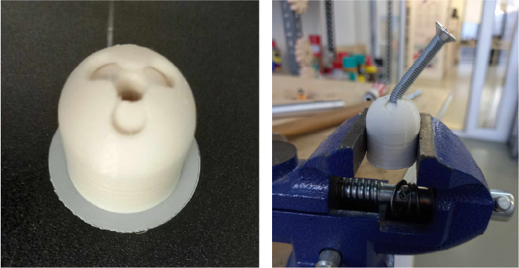 The distance options 0.2
 -
Second attempt:
But the second try was great.I finally get my ball joint.
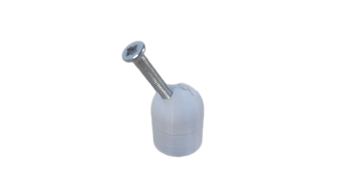
This is my results .The perfect one is a 0.4
![]()
Testing:
Click for downloading
- Ball Joint
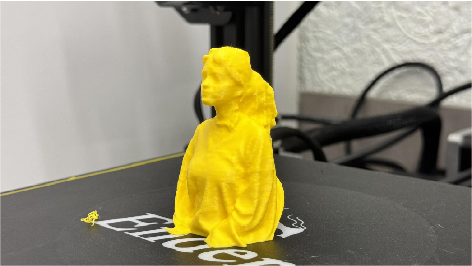
Scaning:
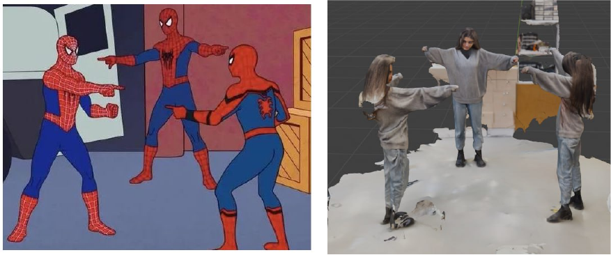
For the 3D scan, I used “Scaniverse” software, which uses iPhone lidar combined with photogrammetry to create a 3D scan.
Set to range:
I can choose between these three options.Or chose the range manually
The scanning process is very simple, I just had to revolve with camera towards the object and that’s it, but the result not so much. I tried many times but never got a better result.
Processing:
At the processing stage, I simply select the detailed option and save it in the format I need


Augmented reality:
This program also has AR and we played in every possible way
The lower part was not scanned very well and in general it would not have been necessary so I lowered the model down the slicer leaving only those places that I needed.

Results:

Conclusion
So this week we’ve been doing a lot of modeling and printing using ABS and PLA plastic. I also designed and printed a mechanical joint that could not be produced subtractively. I also used phone scanning, I liked everything and it is a very useful thing, but phone scanning does not give a detailed and good result, but who wants to make a generalized model or will use it as a sketch for the future - this is what you need, because it free and accessible. Regarding mechanical printing, I can say that this is one of the advantages of the 3rd printer, because it is impossible to do it in other ways.
Click for downloading
- Ball Joint