6. Embedded programming

This week my goal is to learn embedded programming for microcontrollers. This will be very difficult for me, because I first became acquainted with programming in general and electronics in fablabs. I don’t know what will come of this.
Group assignment:
This week our group assignment: compare the performance and development workflows for other architectures. We started comparing the ATtiny1614 and XIAO RP2040 microcontrollers by studying their technical characteristics.
The ATtiny1614 is a member of the AVR family of microcontrollers. It has a built-in 8-bit AVR processor operating at up to 20 MHz, 16 KB flash memory and 2 KB SRAM. It offers a variety of peripherals including UART, SPI, I2C, ADC, PWM, timers and more. The ATtiny1614 is well suited for low power and cost-effective applications due to its compact size and low pin count.
XIAO RP2040 is based on the RP2040 microcontroller manufactured by Raspberry Pi. It features a dual-core ARM Cortex-M0+ processor clocked at up to 133 MHz, 264 KB SRAM and 2 MB flash memory. The RP2040 also offers a rich set of peripherals, including UART, SPI, I2C, ADC, PWM, USB and more. It is designed for a wide range of applications, including Internet of Things, robotics and consumer electronics, and enjoys strong community support and extensive documentation.
So while both microcontrollers offer similar peripherals and capabilities, they target different market segments. The ATtiny1614 is ideal for low-power and cost-effective applications, while the XIAO RP2040 offers higher performance and memory capacity, making it suitable for more demanding projects that require additional processing power and memory resources.
We also compare the performance of ATtiny and RP2040 using the simple equation of 5 + 10/n times 1000. As it turned out, the RP2040 is more than 11 times more powerful than the ATtiny1614.
We also used two different languages micropython and C++ And in the end it turned out that c++ is 100 times more productive than micropython.
After a group assignment, I decided to use AtTiny with c++. Because even though the rp2040 is more powerful, it is much more expensive than the ATtiny. For small projects ATtiny is more convenient and affordable.and with this chip it works much better than micropython
So I got acquainted with the Arduino program in the week of electronics production since we would have to test our boards i already tried this program a little, changed and mixed blink and fade.Here you can find my work
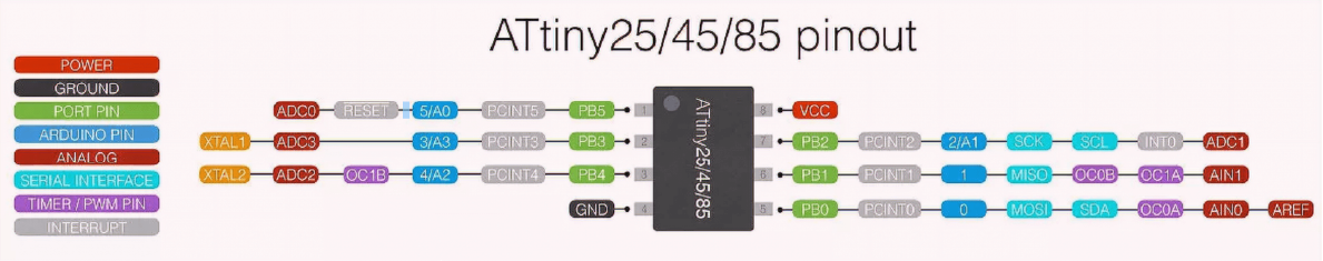
ATtiny
After the group assignment I decided to use AtTiny and that’s why I open the data sheet and found the pins
Tinker Cad
So, before I came to Fab lab, I did a little research on the topic of electronics because I didn’t know anything about it, and I accidentally came across a program called Tinker Cad, which is very simple and I think it is made for beginners and for For me this is the best program to start with.
So, this is an online program created by autodesk, it is free and first we need to register there.
Using Tinker Cad first designed a simple circuit with power and LED.
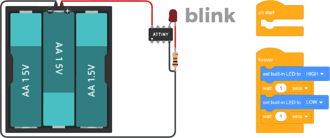
Then I programmed a simple code using blocks that allows the LED to flash.
// C++ code
//
void setup()
{
  pinMode(0, OUTPUT);
}

void loop()
{
  digitalWrite(0, HIGH);
  delay(1000); // Wait for 1000 millisecond(s)
  digitalWrite(0, LOW);
  delay(1000); // Wait for 1000 millisecond(s)
}

Then added code to dim the LED.
Attention!
In this simulator the light does not fade, it is either there or not.
int brightness = 0;
int fadeAmount = 10;

void setup() {


  pinMode(0, OUTPUT);
  pinMode(3, OUTPUT);
}


void loop() {
  analogWrite(3, brightness);
  brightness = brightness + fadeAmount;
  if (brightness <= 0 || brightness >= 255) {
    fadeAmount = -fadeAmount;
  }

  digitalWrite(0, LOW);
  delay(600);

  digitalWrite(0, HIGH);
  delay(600);


}
Thonny
I also install Thonny for MicroPython programming. But i didnt use it.
RP 2040- ARDUINO -C++
In this code i tried to enable the button. I managed to connect everything to the button .
But I noticed another problem that I haven’t solved yet, but I want to share it.
Frst I wrote the code to understand the button and with the button I started to turn on the LED, but since in my code I had another LED blinking, my button worked with a delay due to the delay in the blinking of my LED. While my microcontroller was in delay mode, it did nothing.
int lus2 = 26;
int koj = 27;
int lus = 0;

  void setup() {
  // put your setup code here, to run once:
  pinMode(lus, OUTPUT);
  pinMode(lus2,OUTPUT);
  pinMode(koj, INPUT);

}

void loop() {
  int c1 = digitalRead(koj);
  // put your main code here, to run repeatedly:
  if (c1 == 1) {
    digitalWrite(lus2, 1);

  } else if (c1 == 0) {
    digitalWrite(lus2, 0);

  }
  digitalWrite(lus, 1);
  delay(500);
  digitalWrite(lus, 0);
  delay(500);
}
After that, I changed the code so that when pressed it would show the text and when turned off, another text
int lus2 = 26;
int timeToWait = 1000;
int koj = 27;
int lus = 0;

  void setup() {
  // put your setup code here, to run once:
  pinMode(lus, OUTPUT);
  pinMode(lus2,OUTPUT);
  pinMode(koj, INPUT);
  Serial.begin(9600);
}

void loop() {
  int c1 = digitalRead(koj);
  // put your main code here, to run repeatedly:
  if (c1 == 1) {
    digitalWrite(lus2, 1);
      Serial.println("hello Areg");

  } else if (c1 == 0) {
    digitalWrite(lus2, 0);
      Serial.println("babye Areg");

  }
  digitalWrite(lus, 1);
  delay(timeToWait);
  digitalWrite(lus, 0);
  delay(timeToWait);
}
Morse code
So i did a lot of research and found many ways to optimize the code. ZAnd since I already knew how to blink the light, I decided to make it more interesting.
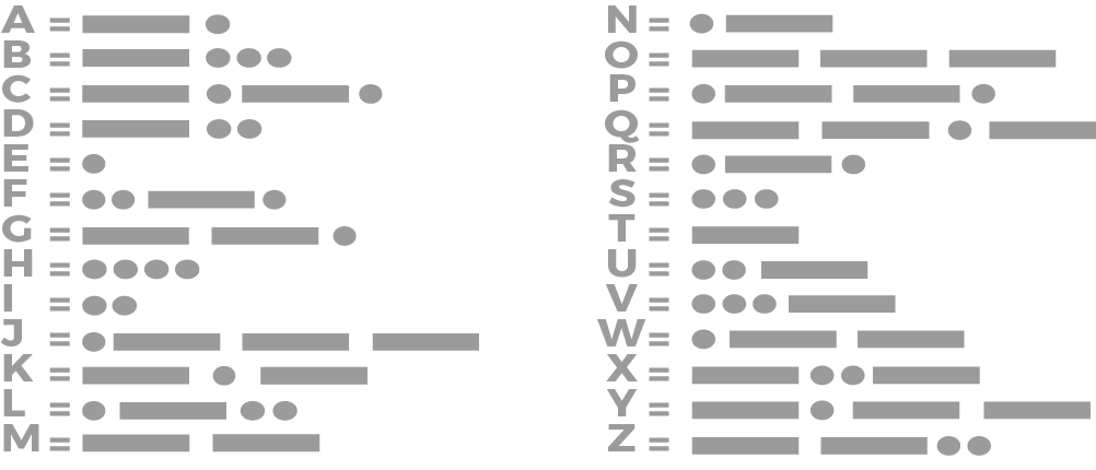
SOS
And i decided to signal SOS in Morse code.
I started at easy way. Manually writing all the values for delay and light.
const uint8_t LED = 26;
const uint8_t BTN = 27;

void setup() {
 pinMode(BTN, INPUT);
 pinMode(LED, OUTPUT);
}

void loop() {

 digitalWrite(LED, digitalRead(BTN));

}
void sos(){
  //Beginning of letter S
  //DOT 1
  digitalWrite(LED, HIGH);
  delay(100); // Wait for 100 millisecond(s)
  digitalWrite(LED, LOW);
  delay(500); // Wait for 500 millisecond(s)
  //DOT 2
  digitalWrite(LED, HIGH);
  delay(100); // Wait for 100 millisecond(s)
  digitalWrite(LED, LOW);
  delay(500); // Wait for 500 millisecond(s)
  //DOT 3
  digitalWrite(LED, HIGH);
  delay(100); // Wait for 100 millisecond(s)
  digitalWrite(LED, LOW);
  delay(500); // Wait for 500 millisecond(s)
  //END of letter S

  //Beginning of letter O
  //DASH 1
  digitalWrite(LED, HIGH);
  delay(500); // Wait for 100 millisecond(s)
  digitalWrite(LED, LOW);
  delay(500); // Wait for 500 millisecond(s)
  //DASH 2
  digitalWrite(LED, HIGH);
  delay(500); // Wait for 100 millisecond(s)
  digitalWrite(LED, LOW);
  delay(500); // Wait for 500 millisecond(s)
  //DASH 3
  digitalWrite(LED, HIGH);
  delay(500); // Wait for 100 millisecond(s)
  digitalWrite(LED, LOW);
  delay(500); // Wait for 500 millisecond(s)
  //END of letter O

  //Beginning of letter S
  //DOT 1
  digitalWrite(LED, HIGH);
  delay(100); // Wait for 100 millisecond(s)
  digitalWrite(LED, LOW);
  delay(500); // Wait for 500 millisecond(s)
  //DOT 2
  digitalWrite(LED, HIGH);
  delay(100); // Wait for 100 millisecond(s)
  digitalWrite(LED, LOW);
  delay(500); // Wait for 500 millisecond(s)
  //DOT 3
  digitalWrite(LED, HIGH);
  delay(100); // Wait for 100 millisecond(s)
  digitalWrite(LED, LOW);
  delay(500); // Wait for 500 millisecond(s)
  //END of letter S

}
Later, I wrote a function to make the constructiin easier, which in the future could be easily changed.
const uint8_t LED = 26;
const uint8_t BTN = 27;


void setup() {
 pinMode(BTN, INPUT);
 pinMode(LED, OUTPUT);
}

void loop() {
  if ( digitalRead(BTN)) {
    sos();
  }

}

void blink(uint32_t pulse, uint32_t pause){
  digitalWrite(LED,HIGH);
  delay(pulse);
  digitalWrite(LED,LOW);
  delay(pause);
}

void sos(){
  blink(100,500)
  blink(100,500)
  blink(100,500)
  blink(500,500)
  blink(500,500)
  blink(500,500)
  blink(100,500)
  blink(100,500)
  blink(100,500)
}
const uint8_t LED = 26;
const uint8_t BTN = 27;

const uint32_t dot = 100;
const uint32_t dash = 500;
const uint32_t pause = 500;


void setup() {
 pinMode(BTN, INPUT);
 pinMode(LED, OUTPUT);
}

void loop() {
  if ( digitalRead(BTN)) {
    sos();
  }

}

void blink(uint32_t pulse, uint32_t pause){
  digitalWrite(LED,HIGH);
  delay(pulse);
  digitalWrite(LED,LOW);
  delay(pause);
}

void sos(){
  uint8_t i;

  for (i = 0; i < 3; i++) { “for” construction, thereby reducing the repetitive action.
   blink(dot, pause); //
  }
  for (i = 0; i < 3; i++) {
   blink(dash, pause);
  }
  for (i = 0; i < 3; i++) {
   blink(dot, pause);
  }
}
My Notbook
C++
Main
void setup() {
  // put your setup code here, to run once:

}
All Void setup commands will be used once
void loop() {
  // put your main code here, to run repeatedly:

}
And all commands entered into Void will be repeated cyclically throughout the program.
Code types
Single signs
char'your simbol here'

//Values - from -128 to 127
unsigned char'your simbol here'

//Values - from 0 to 255
Binary values
bool'true'
bool'false'
Integer values
int'your value'
 //Values - from -32768 to 32767
unsigned int'your value'
 //Values - from 0 to 65535
long int'your value'
 //Values - from 2^31 to 2^31-1
unsigned long int'your value'
 //Values - from 0 to 2^32-1
Attention!
But this may vary in different processor families.
| Comands | AVR | ESP |
|---|---|---|
| short int | from -32768 to 32767 | from -32768 to 32767 |
| unsigned short int | from 0 to 65535 | from 0 to 65535 |
| int | from -32768 to 32767 | from -2147483648 to 2147483647 |
| unsigned int | from 0 to 65535 | from 0 to 4 294 967 295 |
| long int | from -2147483648 to 2147483647 | from -2147483648 to 2147483647 |
| unsigned long int | from 0 to 4 294 967 295 | from 0 to 4 294 967 295 |
To avoid the glitch you can use these similar codes.You need to use these codes because they are unchanged regardless of the processor family
| Comands | Similar code | The value |
|---|---|---|
| short int | int8_t | from -128 to 127 |
| unsigned short int | uint8_t | from 0 to 255 |
| int | int16_t | from -32768 to 32767 |
| unsigned int | uint16_t | from 0 to 65535 |
| long int | int32_t | from -2147483648 to 2147483647 |
| unsigned long int | uint32_t | from 0 to 4 294 967 295 |
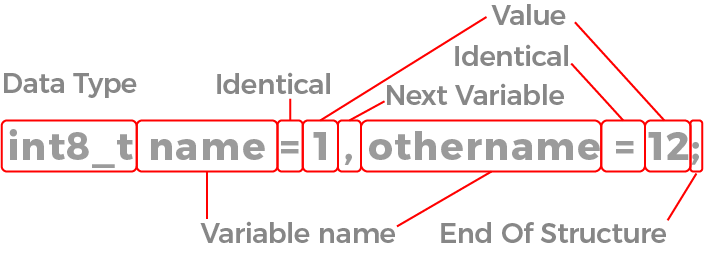
How to read code

Variables
I use this construct to set a variable with value so that I can easily edit the code later.
| Comands | Meaning |
|---|---|
| int8_t name = 1 , othername = 12; | Variable |
float'your value'
Conclusion
During the Fab Academy program this week, I focused my efforts on learning and programming the SOS signal using microcontrollers. I started with the basics, learning how microcontrollers interface with various electronic components and how this knowledge can be applied to create real-world applications. SOS programming was chosen as a practical application of these skills because it requires an understanding of both time delays and output control. During development I used Arduino IDE. This assignment gave me the opportunity to not only improve my programming skills, but also learn how to debug and test my projects to ensure they ran reliably.