9. Output devices
Group Assignment
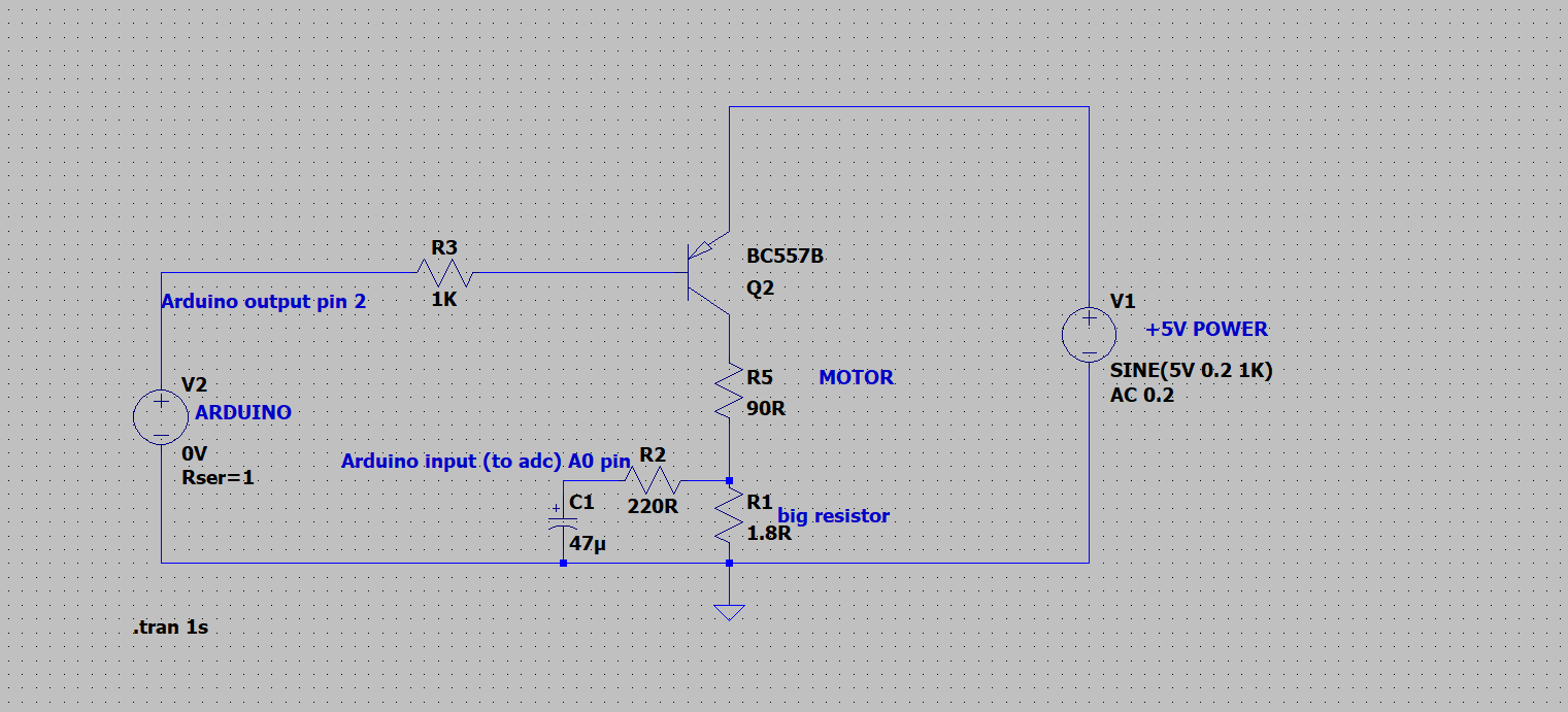
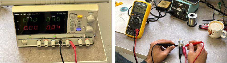 Our group assignment this week was to measure the power consumption of an output device, but I think we did more than just a measurement. First we measured it using a multimeter, then using a benchtop power supply and finally we created a circuit diagram in the LT SPICE simulator. And measured each circuit.
But most importantly, we made the input device from a simple DC motor using the voltage difference between resistors.
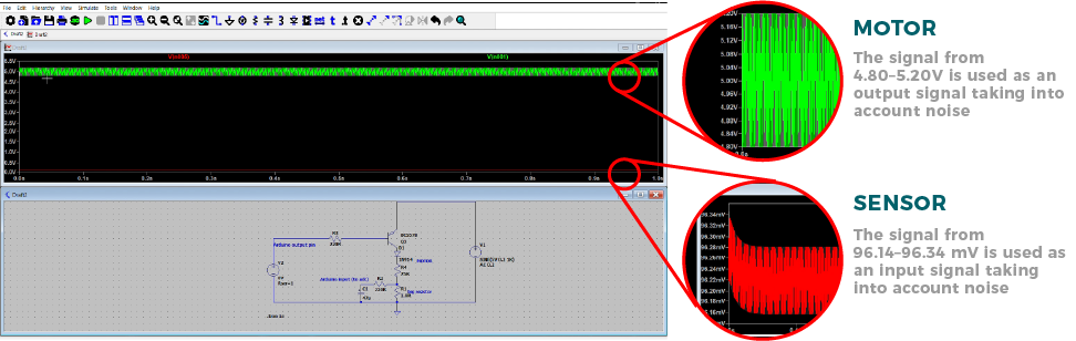
In simple words, we can say that each device has its own internal resistance, and using this diagram we read the back electromotive force of the motor. And when it rose, it meant that something was wrong; in our case, we touched the shaft.
You can read more information here
Individual assignment
This week we had to test several output devices and for this I started with the LCD.
LCD

PCB Production
So this is my device, and it turns out it uses the I2C protocol, but I didn’t take this into account during the Design week and didn’t use the pins they needed.
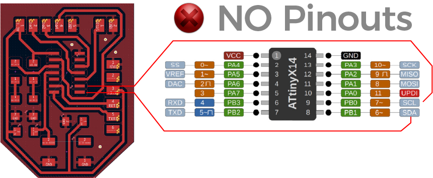
And therefore I was forced to solder the pins directly on the microcontroller.
 And so I finally connected it.

Code
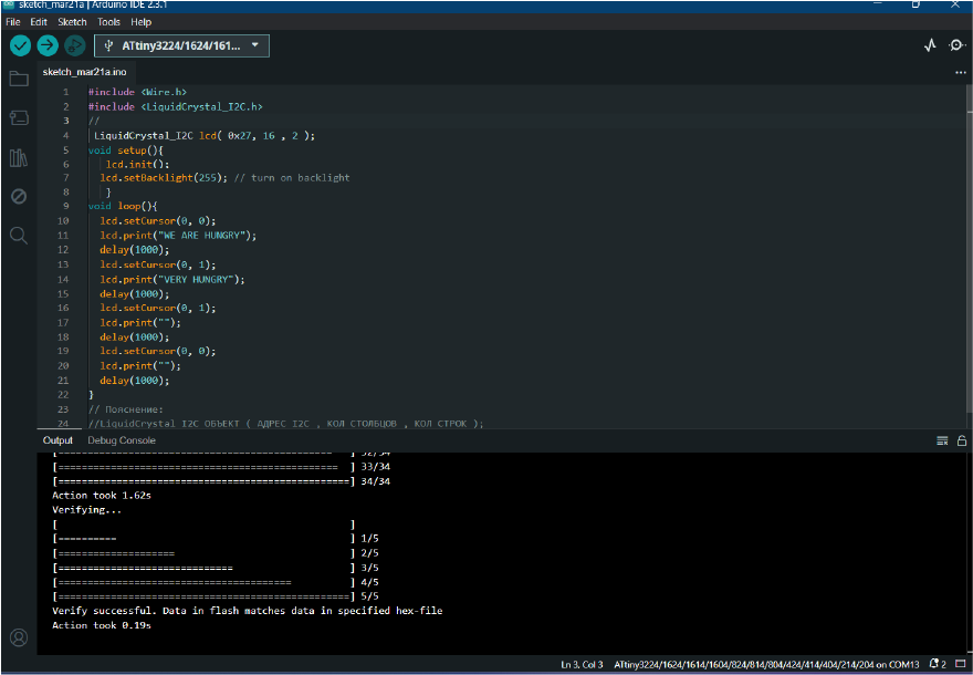
#include <Wire.h>
#include <LiquidCrystal_I2C.h>

 LiquidCrystal_I2C lcd( 0x27, 16 , 2 );
void setup(){
   lcd.init();
  lcd.setBacklight(255); // turn on backlight
   }
void loop(){
  lcd.setCursor(0, 0);
  lcd.print("WE ARE HUNGRY");
  delay(1000);
  lcd.setCursor(0, 1);
  lcd.print("VERY HUNGRY");
  delay(1000);

}
| Code / Line | Explanation |
|---|---|
#include <Wire.h> |
This line includes the Wire library, which provides functions for I2C communication. |
#include <LiquidCrystal_I2C.h> |
This line includes the LiquidCrystal_I2C library, which allows for easy interfacing with I2C LCD displays. |
LiquidCrystal_I2C lcd( 0x27, 16 , 2 ); |
This line initializes an object called lcd of type LiquidCrystal_I2C. It specifies the I2C address of the LCD screen (0x27), the number of columns (16), and the number of rows (2). |
void setup() { } |
This is the setup function, which runs once when the Arduino is powered on or reset. |
lcd.init(); |
This line initializes the LCD screen. |
lcd.setBacklight(255); |
This line turns on the backlight of the LCD screen. The argument 255 sets the backlight to its maximum brightness. |
void loop() { ... } |
This is the loop function, which runs continuously after the setup function. |
lcd.setCursor(0, 0); |
This line sets the cursor position on the LCD screen to the first column of the first row (0-indexed). |
lcd.print("WE ARE HUNGRY"); |
This line prints the string “WE ARE HUNGRY” on the LCD screen. |
delay(1000); |
This line pauses the execution of the program for 1000 milliseconds (1 second). |
lcd.setCursor(0, 1); |
This line sets the cursor position on the LCD screen to the first column of the first row (0-indexed) again. |
lcd.print("VERY HUNGRY"); |
This line prints the string “VERY HUNGRY” on the LCD screen, overwriting the previous message. |
lcd.print("VERY HUNGRY"); |
This line prints the string “VERY HUNGRY” on the LCD screen, overwriting the previous message. |
After writing the code, i loaded it, but it didn’t work and instead of letters it showed squares .
I already started to think that the problem was in the code, but it turned out that the problem was in the brightness adjustment
Turned the screw and everything worked
LED Pattern
Except for the LCD, I decided to use LEDs, but used a bit complex code.
While I did not know how to control a lot of devices with one contact, I decided to use Arduino Uno with breadboard.

I also used 12 blue LEDs with 12 68 ohm resistors (instead of 100 ohm). The assembly was simple, I used pinouts from 2 to 13 conclusions, each LED through a resistor to a separate pin and use the total GND.
Code
And in writing used an array variable
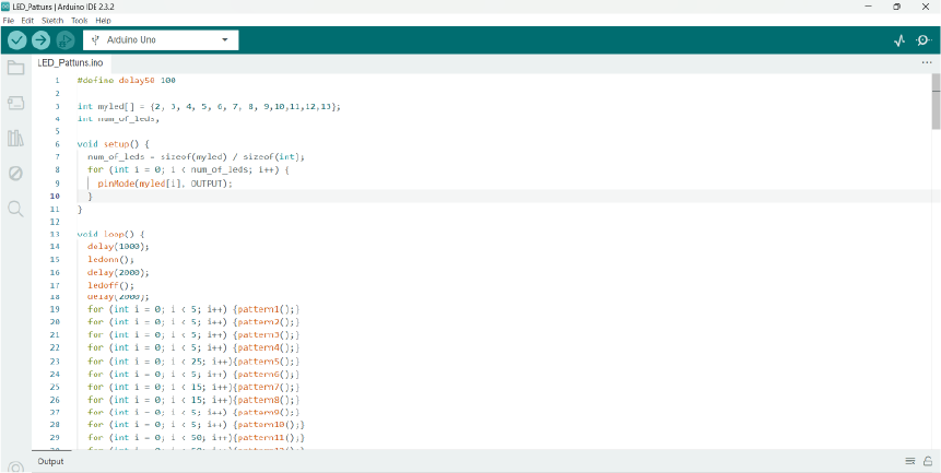
#define delay50 100

int myled[] = {2, 3, 4, 5, 6, 7, 8, 9,10,11,12,13};
int num_of_leds;

void setup() {
  num_of_leds = sizeof(myled) / sizeof(int);
  for (int i = 0; i < num_of_leds; i++) {
    pinMode(myled[i], OUTPUT);
  }
}

void loop() {
  delay(1000);
  ledonn();
  delay(2000);
  ledoff();
  delay(2000);
  for (int i = 0; i < 5; i++) {pattern1();}
  for (int i = 0; i < 5; i++) {pattern2();}
  for (int i = 0; i < 5; i++) {pattern3();}
  for (int i = 0; i < 5; i++) {pattern4();}
  for (int i = 0; i < 25; i++){pattern5();}
  for (int i = 0; i < 5; i++) {pattern6();}
  for (int i = 0; i < 15; i++){pattern7();}
  for (int i = 0; i < 15; i++){pattern8();}
  for (int i = 0; i < 5; i++) {pattern9();}
  for (int i = 0; i < 5; i++) {pattern10();}
  for (int i = 0; i < 50; i++){pattern11();}
  for (int i = 0; i < 50; i++){pattern12();}
  ledoff();
  delay(5000);
}

//TURN ON ALL LEDs
void ledonn() {
  for (int i = 0; i < num_of_leds; i++) {
    digitalWrite(myled[i], HIGH);
  }
}

//TURN OFF ALL LEDs
void ledoff() {
  for (int i = 0; i < num_of_leds; i++) {
    digitalWrite(myled[i], LOW);
  }
}

//LEFT TO RIGHT
void pattern1() {
  for (int i = 0; i < num_of_leds; i++) {
    digitalWrite(myled[i], HIGH);
    delay(delay50);
    digitalWrite(myled[i], LOW);
  }
}

//RIGHT TO LEFT
void pattern2() {
  for (int i = num_of_leds; i > 0; i--) {
    digitalWrite(myled[i - 1], HIGH);
    delay(delay50);
    digitalWrite(myled[i - 1], LOW);
  }
}

//LEFT TO RIGHT FILL
void pattern3() {
  for (int i = 0; i < num_of_leds; i++) {
    digitalWrite(myled[i], HIGH);
    delay(delay50);
  }
  for (int i = num_of_leds; i > 0; i--) {
    digitalWrite(myled[i - 1], LOW);
    delay(delay50);
  }
}

//RIGHT TO LEFT FILL
void pattern4() {
  ledonn();
  delay(delay50);
  for (int i = 0; i < num_of_leds; i++) {
    digitalWrite(myled[i], LOW);
    delay(delay50);
  }
  for (int i = num_of_leds; i > 0; i--) {
    digitalWrite(myled[i - 1], HIGH);
    delay(delay50);
  }
  ledoff();
}

//ALTERNATE LEDs
void pattern5() {
  for (int i = 0; i < num_of_leds; i = i + 2) {
    digitalWrite(myled[i], HIGH);
    digitalWrite(myled[i + 1], LOW);
  }
  delay(delay50);
  for (int i = 0; i < num_of_leds; i = i + 2) {
    digitalWrite(myled[i], LOW);
    digitalWrite(myled[i + 1], HIGH);
  }
  delay(delay50);
}

//OSCILLATING LEDs
void pattern6() {   //osc
  for (int i = 0; i < num_of_leds; i++) {
    digitalWrite(myled[i], HIGH);
    delay(delay50);
    digitalWrite(myled[i], LOW);
  }
  delay(delay50);
  for (int i = num_of_leds; i > 0; i--) {
    digitalWrite(myled[i - 1], HIGH);
    delay(delay50);
    digitalWrite(myled[i - 1], LOW);
  }
}

//INSIDE
void pattern7() {
  for (int i = 0; i < num_of_leds / 2; i++) {
    digitalWrite(myled[i], HIGH);
    digitalWrite(myled[num_of_leds - 1 - i], HIGH);
    delay(delay50);
    digitalWrite(myled[i], LOW);
    digitalWrite(myled[num_of_leds - 1 - i], LOW);
  }
}

//OUTSIDE
void pattern8()
{
  for (int i = (num_of_leds / 2) - 1; i >= 0 ; i--)
  {
    digitalWrite(myled[i], HIGH);
    digitalWrite(myled[num_of_leds - 1 - i], HIGH);
    delay(delay50);
    digitalWrite(myled[i], LOW);
    digitalWrite(myled[num_of_leds - 1 - i], LOW);
  }
}

//LEFT TO RIGHT 3 LEDs
void pattern9() {
  for (int i = 0; i < num_of_leds + 3; i++) {
    if (i <= num_of_leds) {
      digitalWrite(myled[i], HIGH);
    }
    if (i > 2) {
      digitalWrite(myled[i - 3], LOW);
    }
    delay(delay50);
  }
}

//OSCILLATING 3 LEDs
void pattern10() {
  for (int i = 2; i < num_of_leds; i++) {
    if (i == 2) {
      digitalWrite(myled[0], HIGH);
      digitalWrite(myled[1], HIGH);
    }
    digitalWrite(myled[i], HIGH);
    digitalWrite(myled[i - 3], LOW);
    delay(delay50);
  }
  for (int i = num_of_leds - 4; i > -1; i--) {
    digitalWrite(myled[i], HIGH);
    digitalWrite(myled[i + 3], LOW);
    delay(delay50);
  }
}

//RANDOM EFFECT 1
void pattern11() {
  int randomnum = random(0, num_of_leds + 1);
  digitalWrite(myled[randomnum], HIGH);
  delay(delay50);
  digitalWrite(myled[randomnum], LOW);
  delay(delay50);
}

//RANDOM EFFECT 2
void pattern12() {
  int randomonn = random(0, num_of_leds + 1);
  int randomoff = random(0, num_of_leds + 1);
  digitalWrite(myled[randomonn], HIGH);
  digitalWrite(myled[randomoff], LOW);
  delay(delay50);
}
| Code / Line | Explanation |
|---|---|
#define delay50 100 |
This line defines the Delay50 macro with a value of 100. This macro is used to set the delay to 100 milliseconds (0.1 seconds) throughout the code. |
int myled[] = {2, 3, 4, 5, 6, 7, 8, 9, 10, 11, 12, 13}; |
TThis line defines an integer array myled containing the pin numbers to which the LEDs are connected. |
int num_of_leds; |
This line declares an variable named num_of_leds, which will store the number of LEDs in the myled array. |
num_of_leds = sizeof(myled) / sizeof(int); |
This line calculates the number of elements in the myled array by dividing the total size of the array (sizeof(myled)) by the size of the seperate (sizeof(int)). |
for (int i = 0; i < num_of_leds; i++) { ... } |
This line starts a for loop that loops through each element of the myled array. |
pinMode(myled[i], OUTPUT); |
This line sets each LED pin specified in the myled array to the value OUTPUT (within a for loop) |
delay(1000); |
This line introduces a delay of 1000 milliseconds (1 second) |
ledonn(); |
This function turns on the LEDs according to a specific pattern . |
ledoff(); |
This function turns off the LEDs according to a specific pattern . |
for (int i = 0; i < 5; i++) {pattern1();} |
It means that the function will be called 5 times. |
for (int i = 0; i < 25; i++){pattern5();} |
It means that the function will be called 25 times. |
for (int i = 0; i < 15; i++){pattern7();} |
It means that the function will be called 15 times. |
for (int i = 0; i < 50; i++){pattern11();} |
It means that the function will be called 50 times. |
for (int i = 0; i < num_of_leds; i++) {} |
This is a for loop that iterates over each LED. The loop variable i starts from 0 and goes up to 11. |
for (int i = num_of_leds; i > 0; i--){} |
This is a for loop that iterates over each LED. The loop variable i starts from 11 and goes up to num_of_leds 0. |
-
Source files
Click for downloading
LCD ARDINO
LED PATTERN ARDINO
Conclusion
So, the week turned out to be productive because I got acquainted with the i2c protocol, and programmed more complex code than before, and most importantly, I think that our group task is very interesting and we made it from a motor that belongs to an output device and we we made input from it using logic, this is probably the most interesting and we also used a simulator.