4. Electronics production

This week I will finally start making circuit boards, programming them and testing them. I’ve never worked with electronics before and this will be a revelation for me. My goal this week is to learn how to use a small CNC router and make circuit boards.
Group assignment:
How to use milling machine
Preparation First you need to make sure that the design is ready. Using mods to create trajectories and prepare a project. Material needs to be securely fixed to the working platform so that it does not move during milling.
Tool selection And we also need to choose the cutter with which we will work. The choice of cutter must be made during the design or tool path creation process. And we can also use several cutters for contours and traces.
Starting the machine So, in order to start the machine, we need to make sure that the key is not left in the spindle and the safety door is closed before starting our file. You also need to set the Z axis. This can be done in several ways using paper, a multimeter and so on.
Safety and order: Safety and order: You need to keep your machine clean and check it regularly to make sure it remains in good working order. And during work you cannot open the door; you always need to be nearby and observe and, if necessary, make a forced stop
Testing
So in the group task we tested the V-bit because it is much more difficult to use and so we did some depth calculations because the diameter changes for each depth.
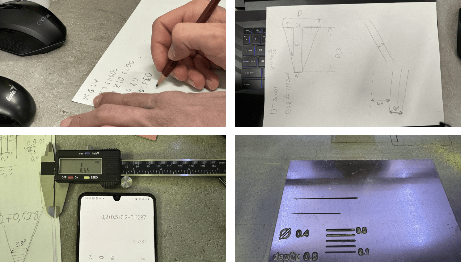
Tangens
So we did some calculations, first using the tangent of the angle to find out at what depth and what thickness, and then Ashot manually wrote Gcode so that our cutter would go down gradually and we would have a segment of different depths and different thicknesses. and then we read this data using a caliper and compared it with our results.
Solid-Calculator
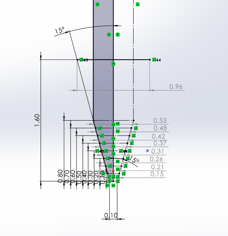
Elen and me also modeled our V-bit with the help of Solidworks and with the help of sketches we created a calculator, so to speak, with which we could set the depth and calculate the diameter of our V-bit at a specific depth.
Individual assignment:
Since I needed to create a printed circuit board, and I didn’t know any software for designing boards at that time, I had to make an already designed circuit. Thats why I decided tu use the original programmer Quentorres created by Quentin Bolsée and redesigned by Adrián Torres.
Customizing:
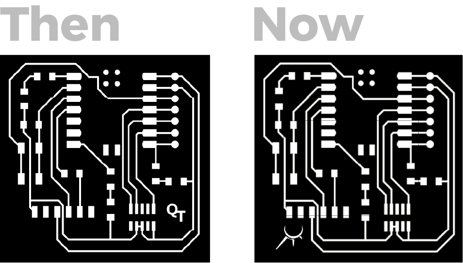
I downloaded png images from the webpage Quentorres and first I tried adding my logotype to the PCB in Adobe Ilustrator program.
First attempt
Failure
But still this attempt failed. I had problems with exporting, setting up G-code and, as a result, with milling; At the next stages I will write what went wrong in more detail.
Second attempt
After failure, I tried to do it differently, downloaded the Kicad file and export it to svg. I then made changes in Adobe Illustrator and then exported the various formats (more details in the next steps).

G-code generation:
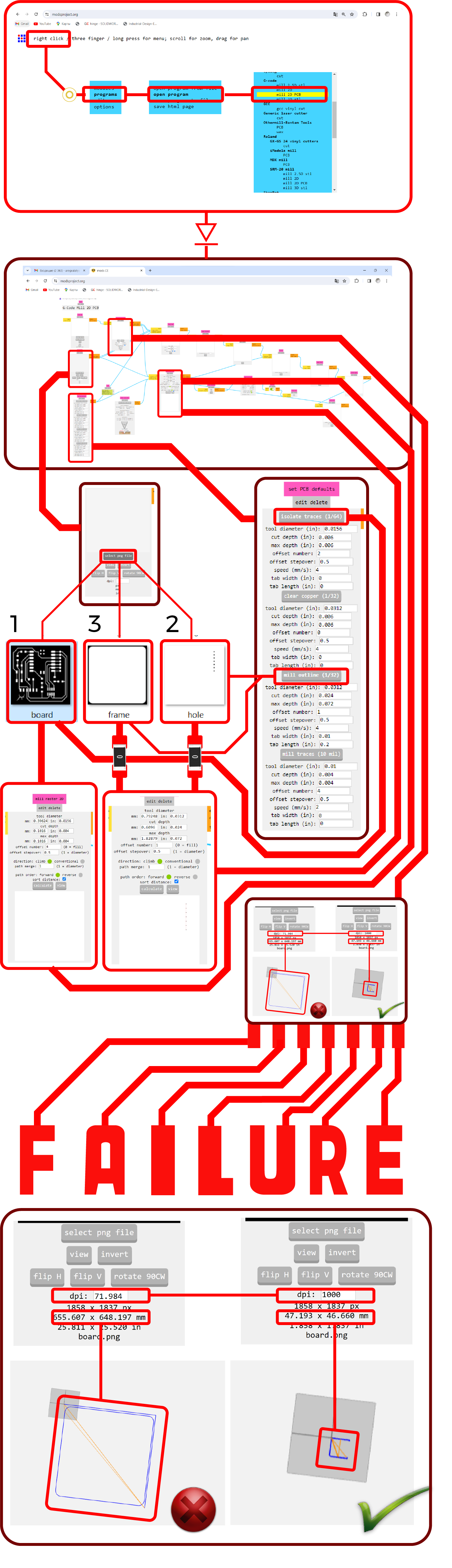
And so first I opened a site Mods for generating G-code.
Failure
So my first mistake was using Adobe Illustrator to design the PCBs, because in export I could not save the size that I needed, not png, not svg.
And now I had a problem with a resolution that was different from the original file and the desired dimensions.
I solved this problem by simply selecting the desired dpi and choosing the appropriate size..
Failure
But unfortunately I forgot to change the dpi in the last G-code which was supposed to cut the board.
I already wrote and showed that on the second attempt I decided to change the printed circuit board a little more.
Success
So I will not go into details of how I made the second attempt because I did everything the same only at the end I did not forget to change the dpi.
I only exported to svg and not PNG those are the only changes.
Milling :
It so happened that Elen made her PCB before me and we found out that the table was uneven and so our instructor Maxim helped us level it.

Material fixation:
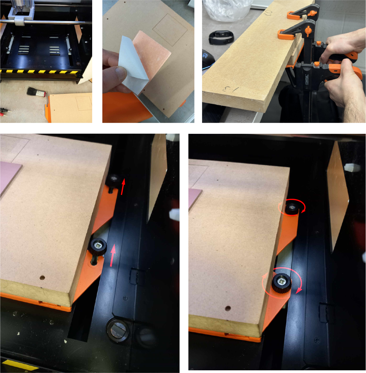
Setting zero coordinates:
After fixing, the first thing we set the zero coordinates for X Y and then Z.

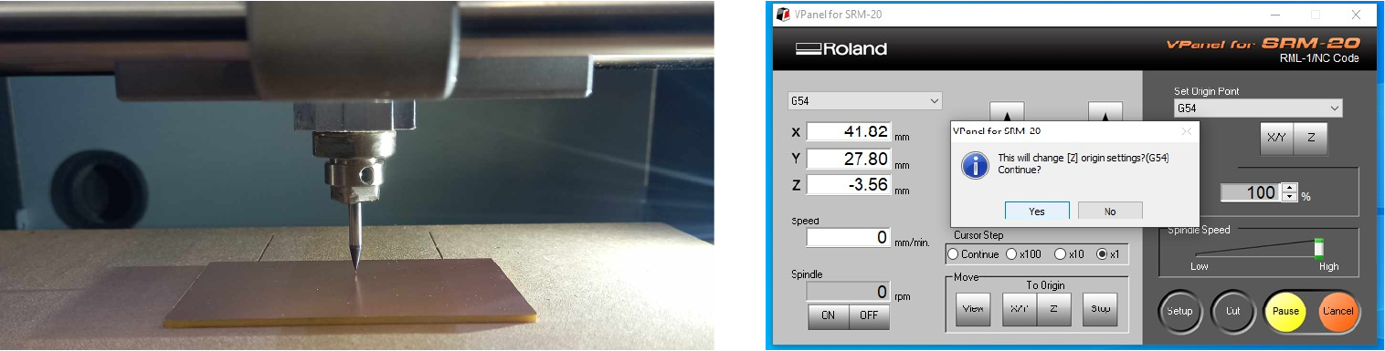
1. Using a multimeter.
I moved the spindle down so that there was about 5 mm between the board and the cutter. Then I carefully move the step by step by step 1., 0.1 and finally 0.01 mm. While holding one contact of the multimeter on the cuter and the other on the board. Multimeter should be on continuity mode . And when the cutter touched the board, there was a sound.
2. Manually.
I moved the spindle down so that there was about 5mm between the board and the cutter. Then I loosen the screw and lower the cutter, being careful not to let it fall.

First defective PCB
Now we will only talk about mistakes because it is very important, I learned a lot there, and about the rest later.

Failure
As I said earlier, when I processed the G-code, I forgot to change the dpi and therefore the g code turned out to be much larger than it was necessary and therefore it converted to the wrong trajectory and I ruined the board.
Failure 2
After that, I corrected the code and tried again, but one of the edges wasn’t cut out. I don’t know why, I checked my g-code with NC-viewer and it looked fine.
Successful attempt
So now I will tell you in more detail how and what I did.
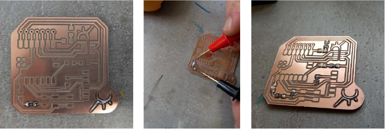
Cutting process:
When I have decided on the coordinates, I close the lid and press “CUT” and select the desired g-codes.
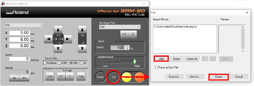
First traces, then holes and cut out. After cutting the tracks, I change the cutter and the zero coordinate. After completing each cut I click “View” and clear the board.
Problems I encountered:
Failure
And so when I changed the cutter, I set it very deep and because of this the milling machine began to behave unusually and didn’t cut.
Question
As it turned out, the distance between the cutter and the platform was greater than the machine limitation.
Success
I solved this problem by moving the cutter down a little.
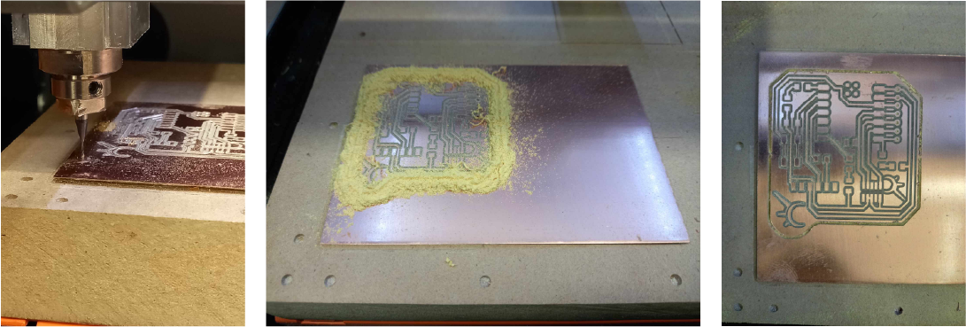
Done:

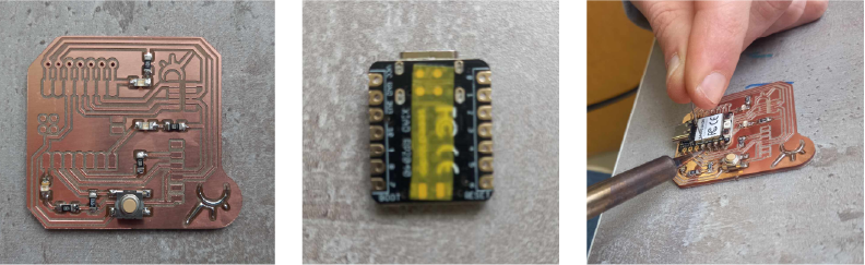
Soldering:
I didn’t have any problems with soldering, since I previously studied to be a jeweler.
I didn’t know how to wire this Sealed Tactile Switch , so I went to the datasheet and found out how to do it.
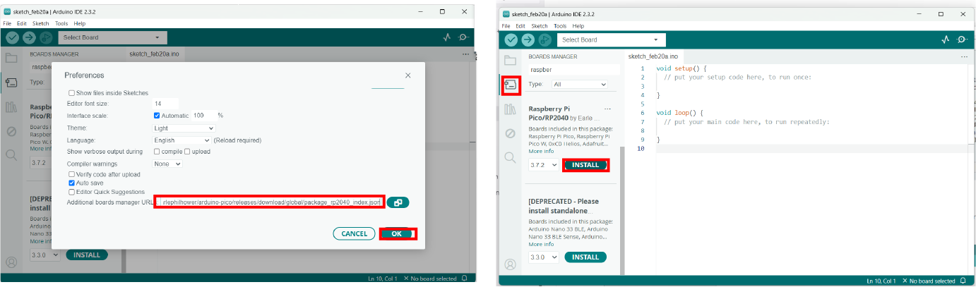
Programming:
- First I download arduino here Arduino Downloads
- Then copy this url Arduino-Pico by Earlephilhower then go in File->Preferences
and past.
- Tools->Board->Board manager and download raspberry pi pico rp2040 boards maneger.
- Code creating
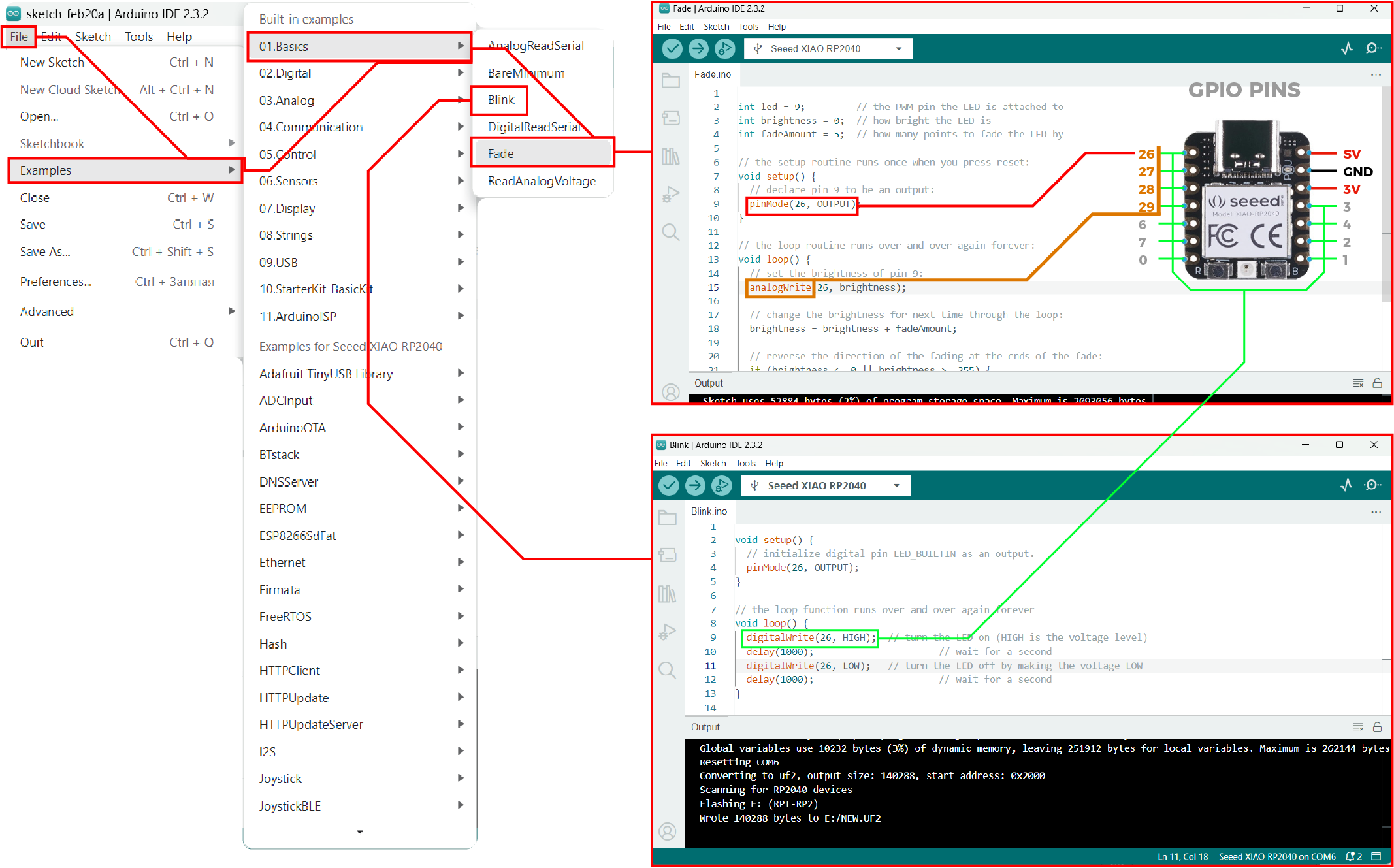
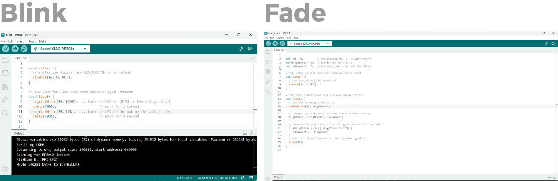
- Then I mixed blink and fade and change the parameters of power

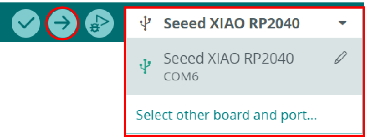
- Select the board and push the code.
int brightness = 0;
int fadeAmount = 10;

void setup() {

  pinMode(1, OUTPUT);
  pinMode(0, OUTPUT);
  pinMode(26, OUTPUT);
}


void loop() {
  analogWrite(26, brightness);


  brightness = brightness + fadeAmount;


  if (brightness <= 0 || brightness >= 255) {
    fadeAmount = -fadeAmount;
  }

  delay(30);
  digitalWrite(1, HIGH);
  digitalWrite(0, LOW);
  delay(600);
  analogWrite(26, brightness);


  brightness = brightness + fadeAmount;


  if (brightness <= 0 || brightness >= 255) {
    fadeAmount = -fadeAmount;
  }

  delay(30);
  digitalWrite(1, LOW);
  digitalWrite(0, HIGH);
  delay(600);
    analogWrite(26, brightness);


  brightness = brightness + fadeAmount;


  if (brightness <= 0 || brightness >= 255) {
    fadeAmount = -fadeAmount;
  }

  delay(30);
}
Testing:
Conclusion
To conclude my Fab Academy experience this week, I want to share my thoughts and discoveries in the field of printed circuit board (PCB) manufacturing, G-code generation, soldering, and PCB programming.
PCB manufacturing was a new and exciting process for me. Although I encountered some failures while creating G-code, these mistakes were valuable lessons. I learned how important it is to carefully check exported files and settings before starting to mill. My first attempts were unsuccessful due to resolution and sizing issues, but after adjusting the dpi and choosing the appropriate size, I was able to achieve the desired result.
Another interesting skill was soldering. And I learned a lot about soldering. And the fact that I mastered silversmithing in the past helped me achieve good results in soldering. This knowledge and skills will definitely be useful to me in future projects.
Finally, I touched lightly on the topic of PCB programming.
Overall, this week was full of discovery and learning. I am grateful for the opportunity to learn from my mistakes and continue to develop.
-
Source files
Click for downloading
Traces and Cutout SVGs
G-code
Blink Arduino
Week challenges
- Linked to the group assignment page
- Documented how you made the toolpath
- Documented how you made (milled, stuffed, soldered) the board
- Documented that your board is functional
- Explained any problems and how you fixed them
- Uploaded your source code
- Included a ‘hero shot’ of your board
- Make and test a microcontroller development board
- Described the process of tool-path generation, milling, stuffing, de-bugging and programming
- Demonstrate correct workflows and identify areas for improvement if required.