3. Computer controlled cutting

Group assignment:
Characterize your lasercutter’s
- Focus
- Power
- Speed
- Rate
- Kerf
- Joint clearance types
Document your work to the group work page and reflect on your individual page what you learned.
The first thing we did with the group, we did a lot of tests and found out what the maximum speed of our laser machine is for engraving and cutting.
How we did it
For this purpose we have created lines with a total length of 10000 mm and speed 1000 mm seconds. And with the laser turned off (so as not to waste material) we conducted a test.
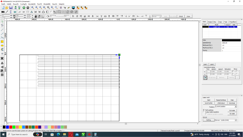

And then based on these results we carried out several more tests on engraving on cardboard at different speeds and power.
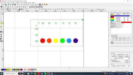
I would like to note that before this test I could not resist and conducted my own individual tests, which I will write about later. As a result of these tests, the approximate power of the engraving became clear.
What did we get

Individual tests
And after these tests, when I realized that with engravings i can get different shades, I got the idea to make a picture using 3 colors - light and dark shades with engraving and medium ones using the color of cardboard
Design principles.

Steps.
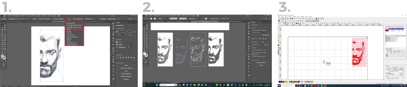
- I used my self-portrait.
- Then traced the image in Adobe Ilustrator by using a trace color 3 and then exported it into 3 different vectors- 2 engravings and one for cutting.
- And in the laser program I gave them these parameters.
- Black-Mode:Laser Scan, Speed:300 mm/s, Power:14%
- White- Mode:Laser Scan, Speed:300 mm/s, Power:12%
- Cut (background)-Mode:Laser Cut, Speed:30 mm/s, Power:20%
Result.
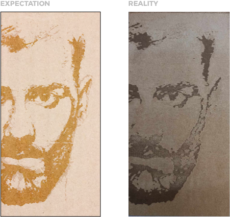
And so my expectations were not met
This experience was extremely useful because I found that the result is influenced by many factors, such as the difference in the material used in different places from the same material, warping, and even the length of the acceleration path, etc.
Individual assignments
- Design
- Lasercut
- Document a parametric construction kit, accounting for the lasercutter kerf, which can be assembled in multiple ways.
Kerf test for joints.
After group assignment i also designed kerf testing file .And as i designed it parametric it became as universal for every sheet material.Because i can change all parameters by changing material thickness.
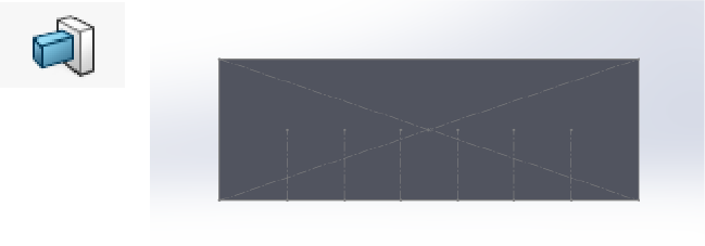
- First i sketched rectangle then draw axis and made it parametric.Now i can change dimensions by changing number of axis.

- Then I use boss extrude and create a solid.
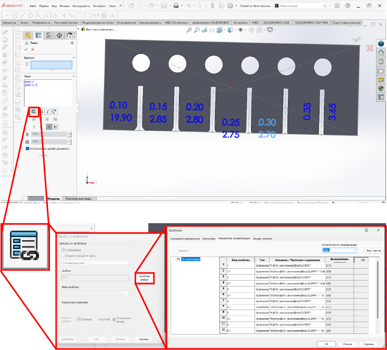
- Then I draw rectangles for cutting and set them to increase in parameters by 0.5 each next cut.And added some circles for future cutting or engraving tests.

- And set the final parameters.

- Than added various roundings to check simple input.

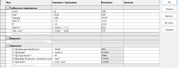
- And finally, I add marks and dimensions linked to the my file parameters.
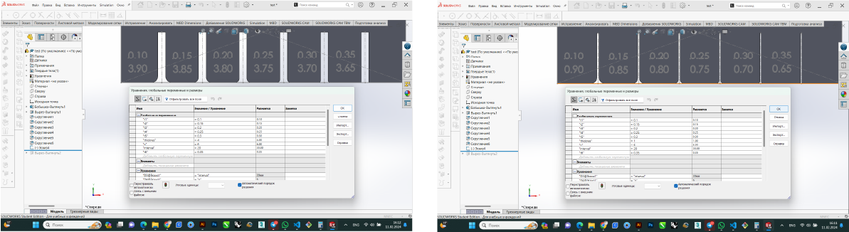
- This is what my equations look like before and after.
- After the design, I redacted the colors in Illustrator and then export it to a laser cutting program

- Well here is the result.

Lampshade made from waste plywood
So, in the previous assignment I was developing my final project. It turned out that I wouldn’t be able to do anything related to my project this week, so I decided to use wastes from my upcoming project so that the material wouldn’t go to waste and something beautiful would come out.
And since this is not my final project, and I don’t want to waste a lot of material, this will only be a prototype made from cardboard.
So like i said i know which form i will use.
-
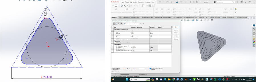
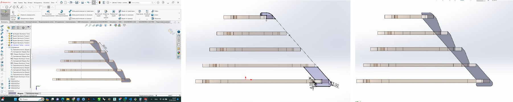
And for this I create a sketch in SolidWorks and draw a triangle with rounded corners.Second thing that i will do i draw many small triangles by help offset curve tool.
-
And here i will not care about kerf, but in the future i have to use it in the equations. Thereforei write the tool diametr parametr and set the parameters for the thickness of my material,weight of my offset.
-
Next I create an assembly from my part.

-
Then I create the joints and set the parameters for them.


-
Repeat the forms using a circular array

-
Then I tried to change my parameters

-
And in that assembly create new detail for lamp frame , by following equations.And create a circular array

-
And so finally the end completed the development and made it out of cardboard using a laser cutter.
Failure
Well, to be honest, the last detail suited me very much, since it did not change with the parameters and was a little difficult to install.
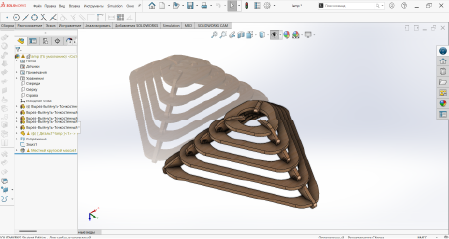
So I deleted this item and tried everything again
-
Drew a sketch and extruded
-
Tried changing the parameters. Everything worked
-
Created a line array and noticed my sketch was wrong. So I changed it.
-
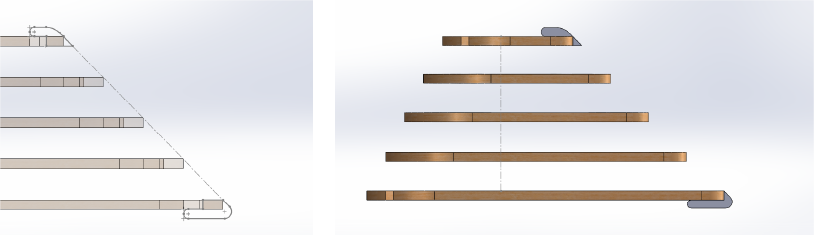
Checked the possible maximum and minimum height, and set a limit of at least 3 mm.

-
And when I wanted to set the parameter to less than 2 mm, the algorithm worked and did not allow me to do this.And in the same way I set the Maximum height limit to 25mm and everything worked perfectly.
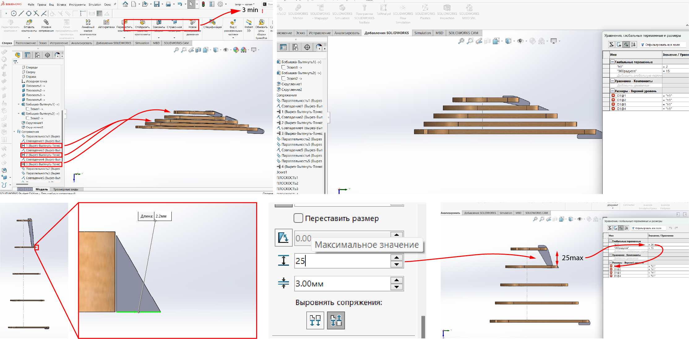
-
Setting parameters in linear array.
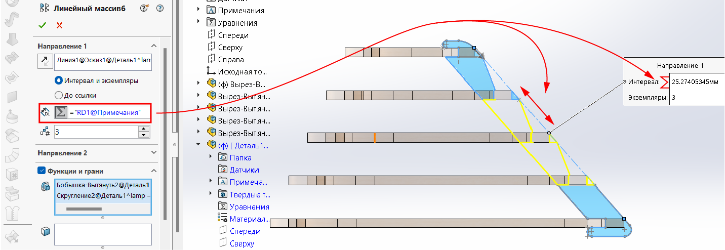
-
Tried to change interval parameter, and its worked as I planned.
-
And created a circular array.

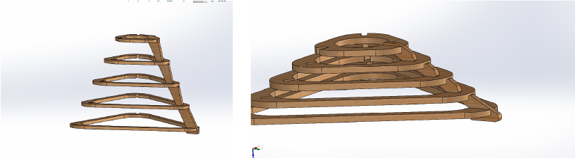
-
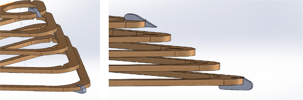
Well, I finally got everything working perfectly. And when I tried to change some parameters, everything changed: thickness, triangle, tool diameter, etc.

Result
- As a result, I received a lamp, the design of which can be completely changed depending on the size of my workpiece, tool diameter and the thickness of the material


Conclusion
- I can’t say that everything was simple, everything was very difficult, because I did the opposite, did not take the design and therefore chose the material for the design. I first chose a material with a specific shape, its dimensions, and then I started cutting, and that’s why I had a lot of problems.
- The second problem arose from the fact that I did not use individual parts. On the contrary, my entire project was made up of one part, like a nesting doll, they were inside each other and therefore my kerf affected all parts.
- And the third problem I had three files with which I worked, one for the triangle , the other for the assembly and one separate part. And when I tried to change something in my parameters I had to open the separate parts and change it all there, well it’s not a mistake because I wanted to use scraps from my future projects and this is the way I could do it.
In conclusion, I can say that the next time I happen to work with such parts, I will make everything one part, not an assembly, create a multi-body part and then export it to a vector program and set the offsets for cutting. I think it’s much easier than doing everything like this.
Vinyl cutter
Cut something on the vinyl cutter.
This is the first time I use a vinyl cutter.
So I decided to cut out my logo, it should come first.
And so I already have a file.
Beginnings
So first of all we got acquainted with the instructions. How to use and care for the plotter.
And most importantly, what not to do. You will find all this in this link. - Instructions
Export/Import
And the first thing I tried to cut the Illustrator file, because Incape has the ability to import AI files.
But unfortunately it didn’t work
Then I tried to export my files to SVG
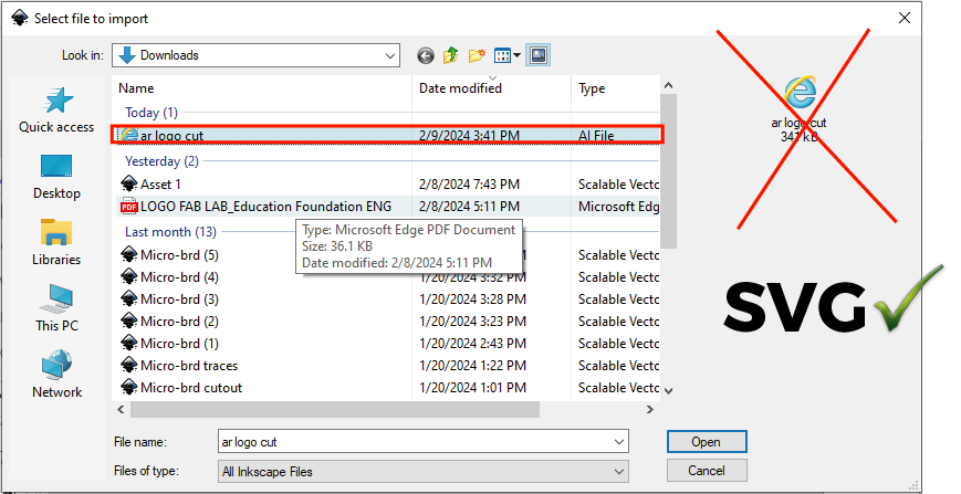 It worked with SVG
Testing
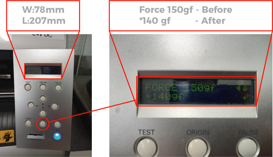
Before the final work I needed to do some tests. Since the ploter has two parameters, I needed to try these 2 parameters on each material.
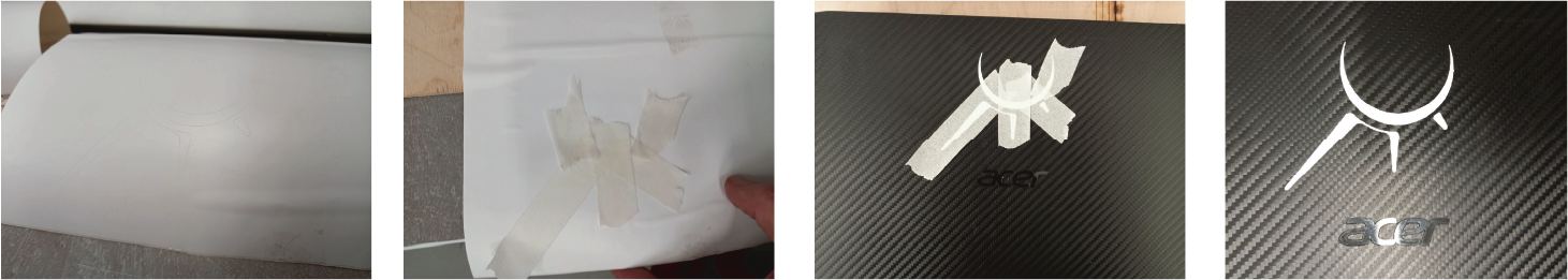
For the first time I tried black matte vinyl. And with the 150 power settings it worked great.
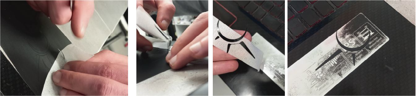
But I had one problem.
My computer is as black as the sticker.
And then I decided to use white Oracle and conduct several experiments for educational purposes.
 I took and cut out a test file with different parameters from 50 to 150.
So the results were like this: from 50 to 110 it doesn’t cut at all. There are already 130 to 150 reductions, but you need to understand that you always need to choose the golden mean. Because if we take a smaller number, we may have problems. If I take more, the knife may wear out quickly.

The working process
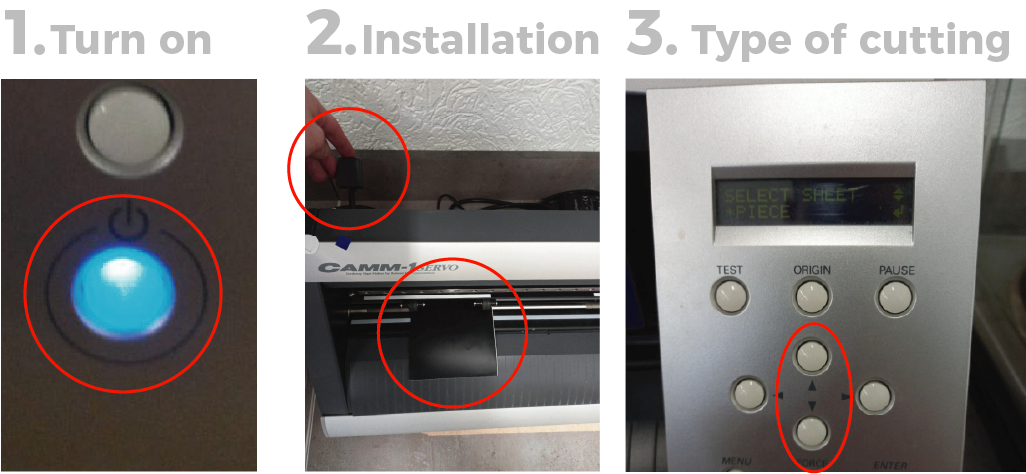
- Turn on the ploter
- Insert the material into the desired place on the sensor with positioning to the left between the rollers.
- Next I chose “piece” because my material is less than 160 cm.


Completion

Post-Production
Result

-
Source files
Click for downloading - Solid parametric
- Vectors
- Test
Learning outcomes
-
Demonstrate and describe parametric 2D modelling processes.
-
Identify and explain processes involved in using the laser cutter.
-
Develop, evaluate and construct a parametric construction kit.
-
Identify and explain processes involved in using the vinyl cutter.
-
Linked to the group assignment page.
-
Explained how you created your parametric design.
-
Documented how you made your press-fit construction kit.
-
Documented how you made something with the vinyl cutter.
-
Included your original design files.
-
Included hero shots of your results.