Group Assisnment Week 6
This week’s assignment included the following tasks:
- Browse through the data sheet for your microcontroller, compare the performance and development workflows for other architectures.
RP2040 Microcontroller Summary
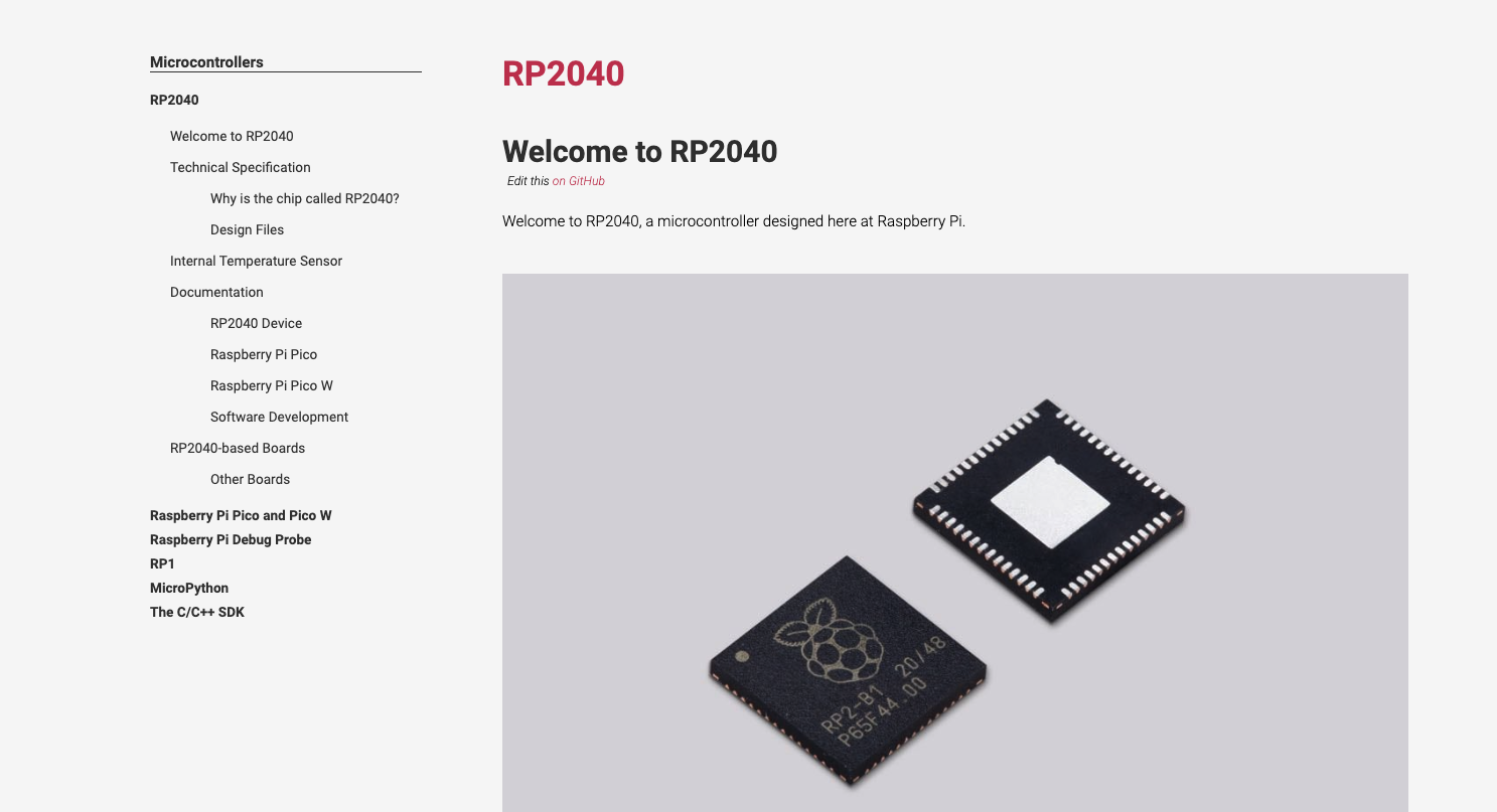
I am reading the RP2040 Microcontroller datasheet from here.
Here are some specification of it:
- Dual-core Arm Cortex-M0+ processor, up to 133 MHz
- 264KB of on-chip SRAM
- Support for up to 16MB of off-chip Flash memory via dedicated QSPI bus
- DMA controller
- Interpolator and integer divider peripherals
- 30 GPIO pins, 4 of which can be used as analog inputs
- 2 UARTs, 2 SPI controllers, and 2 I2C controllers
- 16 PWM channels
- USB 1.1 controller and PHY, with host and device support
- 8 Programmable I/O (PIO) state machines for custom peripheral support
- Power modes: Active, Dormant, and Off
The RP2040 microcontroller offers several key features and capabilities:
These information I got is actually from the manufacturer of RP2040, Raspberry Pi. In this page, I have known the structure of RP2040 and the board regarding them:
- External memory execution: Code can be run directly from external memory via dedicated SPI, DSPI, or QSPI interfaces, with a small cache to enhance performance.
- Debug support: The microcontroller supports debugging through the SWD interface.
- Internal SRAM organization: The on-chip SRAM is organized in banks that can store code or data. These banks are accessed through dedicated AHB bus fabric connections, enabling bus masters to access separate bus slaves without stalling.
- DMA bus masters: The microcontroller includes DMA bus masters to handle repetitive data transfer tasks, offloading these tasks from the processors.
- GPIO functionality: GPIO pins can be driven directly or by various dedicated logic functions.
- Dedicated hardware peripherals: The microcontroller features dedicated hardware for common functions such as SPI, I2C, and UART.
- Programmable I/O (PIO) controllers: Flexible and configurable PIO controllers are available to support a wide range of I/O functions.
- USB connectivity: An integrated USB controller with an embedded PHY provides Full-Speed/Low-Speed Host or Device connectivity, managed by software.
- Analog-to-Digital Converter (ADC): The microcontroller includes four ADC inputs that are shared with GPIO pins.
- Clock management: Two Phase-Locked Loops (PLLs) generate a fixed 48MHz clock for USB or ADC and a flexible system clock up to 133MHz.
- Internal Voltage Regulator: An on-chip voltage regulator supplies the core voltage, simplifying the end product's power supply requirements by only needing to provide the I/O voltage.
Some common and important things for development should be:
- The Pin Locations, Descriptions and GPIO Functions, the MCU board might not apply them all but can take it as a reference:

The ARM Cortex-M0+ processor features and benefits are:
- Tight integration of system peripherals reduces area and development costs.
- Thumb instruction set combines high code density with 32-bit performance.
- Support for single-cycle I/O access.
- Power control optimization of system components.
- Integrated sleep modes for low-power consumption.
- Fast code execution enables running the processor with a slower clock or increasing sleep mode time.
- Optimized code fetching for reduced flash and ROM power consumption.
- Hardware multiplier.
- Deterministic, high-performance interrupt handling for time-critical applications.
- Deterministic instruction cycle timing.
- Support for system level debug authentication.
- Serial Wire Debug reduces the number of pins required for debugging.
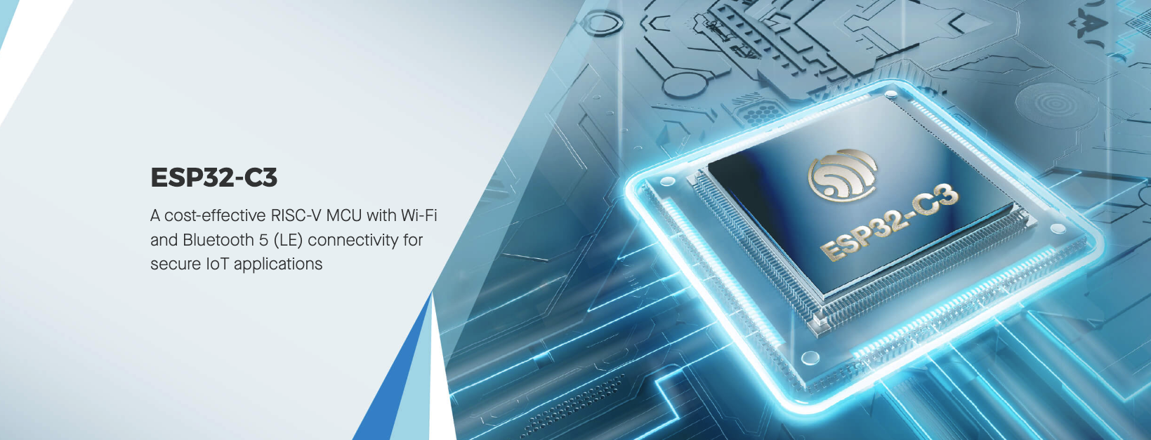
RISC-V Microcontroller (ESP32-C3) Summary
I am reading the ESP32 Microcontroller datasheet from here.
These information I got is actually from the manufacturer of RP2040, ESPRESSIF. In this page, I have known the structure of ESP32C3 and the module and the Devkits regarding them:
- Single-core 32-bit RISC-V processor, up to 160 MHz
- 400KB of on-chip SRAM
- 384KB of ROM
- 802.11b/g/n Wi-Fi
- Bluetooth 5 (Bluetooth LE)
- 22 programmable GPIOs
- 12-bit ADC, 8-bit DAC
- UART, SPI, I2C, I2S, and GDMA interfaces
- PWM and LED PWM controllers
- Hardware cryptography acceleration
- Power modes: Active, Modem-sleep, Light-sleep, Deep-sleep, and Hibernation
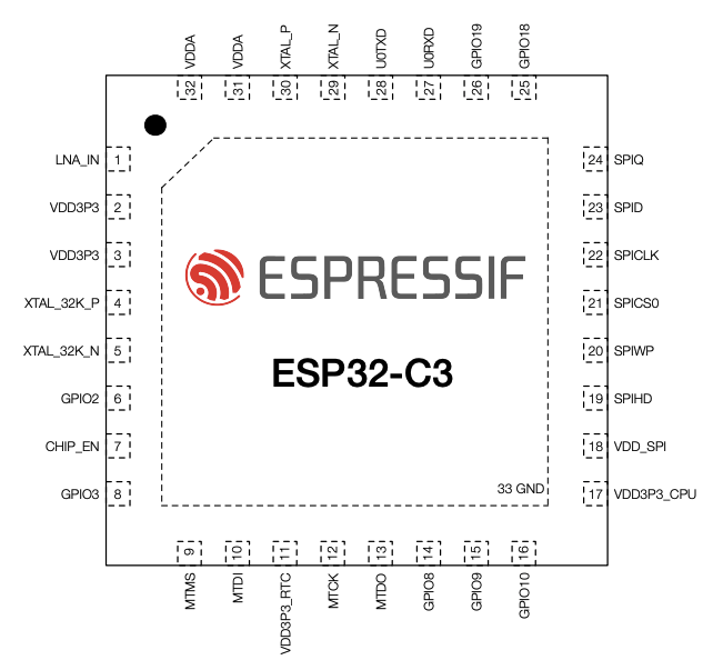
Some common and important things for development should be:
- The Pin Locations, Descriptions and GPIO Functions, the MCU board might not apply them all but can take it as a reference:
The ESP32-C3, with its RISC-V architecture and wireless capabilities, offers a different set of features compared to the RP2040. It has a single-core processor but a higher clock speed, and includes wireless connectivity which the RP2040 lacks. The development workflow for ESP32-C3 typically involves using the ESP-IDF (IoT Development Framework) with C/C++, or the Arduino framework.
Performance and Usage Comparison
| Microcontroller | Processor | Clock Speed | On-chip SRAM |
|---|---|---|---|
| RP2040 | Dual-core Arm Cortex-M0+ | Up to 133 MHz | 264KB |
| ESP32-C3 | Single-core 32-bit RISC-V | Up to 160 MHz | 400KB |
Taking XIAO RP2040 and XIAO ESP32C3 as an example.
If developing them with Arduino, there are different settings for perferences:
For XIAO RP2040 should add this url:
https://github.com/earlephilhower/arduino-pico/releases/download/global/package_rp2040_index.json
For XIAO ESP32C3 should add this url:
https://raw.githubusercontent.com/espressif/arduino-esp32/gh-pages/package_esp32_index.json
And the PIN is different as well.
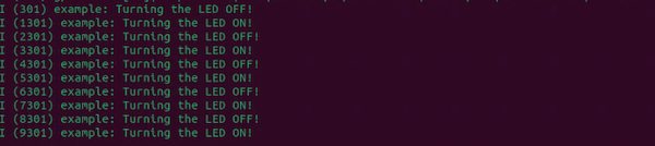
There is additional way to develop these two boards, which is using MicroPython, apply "Thonny" tool.
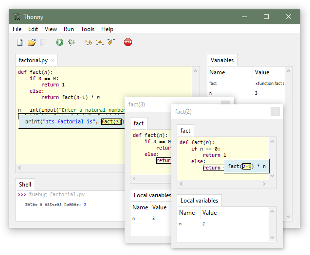
I have applies the Thonny tool in my week 12(testing but no good), week 14(working on MQTT).
There is specifc tool for developing XIAO ESP32C3 which is designed by the company ESPRESSIF: ESP-IDF
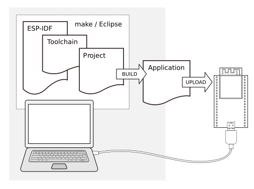
I have tested it in week 12 as well.