Microcontroller Development
Updated on 5.16th, I am told I should use tha board that my design. Hence, I will need the board I design in the week 4 and program with it.
Updated on 5.11st, I am catching my assignments up and I have the ready components. And I am kind of familiar with the electronics so this time is pretty easy to me.
Program my MCU board
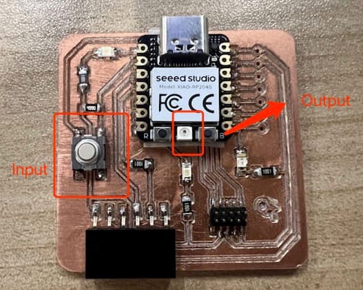
I am going to use my designed board on from week 4 and program it. I am going to use button as the input and the RGB light on the board as output"
RGB light testing as the output
From the Seeed example Wiki I find this code and I copy and upload to my XIAO RP2040 board.
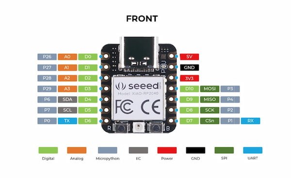
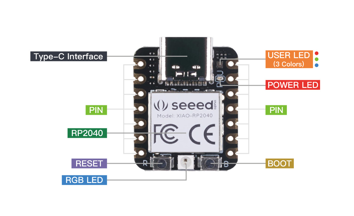
I check the ports for XIAO RP2040(and RP2040 chip):
I download the schematic diagram for XIAO RP2040 from the Seeed Studio Wiki, and check the port between the RGB and the XIAO RP2040:
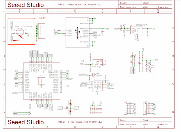
The schematic diagram is actually from Seeed Studio Wiki Platform, and presenting under the "resource" part, of XIAO ESP32C3 Getting Started.
Turns out that the input port of RGB DIN is connecting NEOPIK and the NEOPIK is connecting to the GPIO12 of the RP2040 chip:
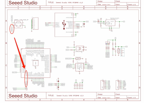
Since there are no presented port for XIAO RP2040 board, I then will use GPIO12 port as the chip port.
#include <Adafruit_NeoPixel.h>

int Power = 11;
int PIN  = 12;
#define NUMPIXELS 1

Adafruit_NeoPixel pixels(NUMPIXELS, PIN, NEO_GRB + NEO_KHZ800);

void setup() {
  pixels.begin();
  pinMode(Power,OUTPUT);
  digitalWrite(Power, HIGH);

}

void loop() {
  pixels.clear();
  pixels.setPixelColor(0, pixels.Color(15, 25, 205));
  delay(400);
  pixels.show();
  pixels.clear();
  pixels.setPixelColor(0, pixels.Color(103, 25, 205));
  delay(400);
  pixels.show();
  pixels.clear();
  pixels.setPixelColor(0, pixels.Color(233, 242, 205));
  delay(400);
  pixels.show();
  pixels.clear();
  pixels.setPixelColor(0, pixels.Color(233, 23, 23));
  delay(400);
  pixels.show();
  pixels.clear();
  pixels.setPixelColor(0, pixels.Color(12, 66, 101));
  delay(400);
  pixels.show();
  delay(500);

}
Add input(button) into the function
From the schematic map from week 4:
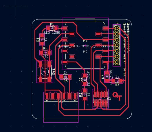
I understand the port of the board is D1. Meanwhile, I want to use button to change the color of RGB presenting. Hence the code(generated by GPT):
#include <Adafruit_NeoPixel.h>

int Power = 11;
int PIN = 12;
int ButtonPin = 27;  // 按钮连接的引脚
#define NUMPIXELS 1

Adafruit_NeoPixel pixels(NUMPIXELS, PIN, NEO_GRB + NEO_KHZ800);

void setup() {
  pixels.begin();
  pinMode(Power, OUTPUT);
  digitalWrite(Power, HIGH);
  pinMode(ButtonPin, INPUT_PULLUP);  // 将按钮引脚设置为输入,并启用内部上拉电阻
}

int colorIndex = 0;  // 当前颜色索引
bool lastButtonState = HIGH;  // 上一次按钮状态

void loop() {
  bool currentButtonState = digitalRead(ButtonPin);

  // 检测按钮从未按下到按下的状态变化
  if (lastButtonState == HIGH && currentButtonState == LOW) {
    colorIndex++;  // 切换到下一个颜色
    if (colorIndex > 4) {
      colorIndex = 0;  // 如果超出颜色范围,则重置为0
    }

    setColor(colorIndex);  // 设置LED颜色
  }

  lastButtonState = currentButtonState;  // 更新按钮状态
  delay(50);  // 简单的消抖延时
}

void setColor(int index) {
  uint32_t colors[] = {
    pixels.Color(15, 25, 205),   // 蓝色
    pixels.Color(103, 25, 205),  // 紫色
    pixels.Color(233, 242, 205), // 浅黄色
    pixels.Color(233, 23, 23),   // 红色
    pixels.Color(12, 66, 101)    // 深蓝色
  };

  pixels.clear();
  pixels.setPixelColor(0, colors[index]);  // 设置指定颜色
  pixels.show();
  delay(400);  // 延时以便观察颜色变化效果
}
Finally I have the output:
Exract Credit ✨
The below one is just the extract credit.
Write something at the front
In this week I should write a program for a Seeed Studio XIAO RP2040, to interact (with local input &/or output devices) and communicate (with remote wired or wireless devices). Since the components are full ready yet, I am going to write something that I have in mind to achieve the sensing and interacting.
The idea of mine is that:
- During my working place, I should be attention about the environment. And I am going to use a fundamental sensor to sense the temperture and humidity for where I work.
- When it comes to a certain value, like below 22 degree, there will be a notification to wrong me that I should do something.
Hardware I am going to use
I am going to use the hardware below:
Microcontroller - XIAO RP2040

RP2040 is the debut microcontroller from Raspberry Pi. It brings signature values of high performance, low cost, and ease of use to the microcontroller space. Thus I think Seeed Studio XIAO RP2040 have the right performance for my project.
XIAO RP2040
Input - Grove - AHT20 Sensor

Grove - AHT20 I2C industrial grade temperature and humidity sensor can help me with its fast response speed and strong anti-interference ability. It can guarantee normal use in harsh environments it suits my requirements.
Grove - AHT20
Output - RGB light on XIAO RP2040
I found there is a RGB light on the XIAO RP2040, which is very convenient for my project. And the best part is that there are official wiki supporting it. I can use them as my example.
RGB Usage Example
Addition - Expansion Board Base for XIAO

This board is focusing on XIAO and providing rich peripherals for XIAO. It enables building prototypes and projects in an easy and quick way, which is nice and neat for me.
XIAO Expansion
To sum up
I want the sensor to detect the temp and humid around my workplace, then use the RGB to notice me when the humidity is way beyond some level. This all happening on one integrated board.
Prerequisite
Hardware Part
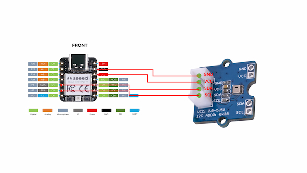
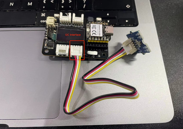
For the hardware part, I should check schematic diagram for XIAO RP2040 microcontroller and RP2040 chip, as well as the input sensor: Grove - AHT20 Sensor. From the Grove - AHT20 Sensor wiki I understand that this sensor is digital output and transmitting data with I2C interface.
The key features for I2C interface/communication:
- Two-Wire System: I2C communication requires only two wires: a Serial Data Line (
SDA) and a Serial Clock Line (SCL). - Multi-Master Support: I2C allows for multiple master devices and multiple slave devices to coexist on the same bus.
Addressing Concept: Each slave device is identified by a unique address, enabling a master device to select and communicate with specific slaves.- Synchronous Communication: All data transfers are synchronized with the clock signal, which is provided by the master device controlling the communication.
For knowing Addressing Concept better is that: multiple I2C interface modules can work at the same time with one microcontroller.
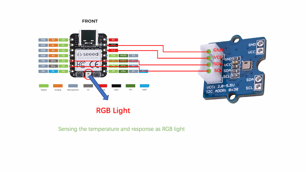
Anyway, after understanding the interface for Grove sensor, I check the ports for XIAO RP2040(and RP2040 chip) as well:
And notice the SDA port is on D4, the XIAO RP2040 board, (where GPIO6 on RP2040 chip); and the SCL port is on D5, the XIAO RP2040 board, (where GPIO7 on RP2040 chip). Hence the connection should be(wrote it on the powerpoint):
Meanwhile, I download the schematic diagram for XIAO RP2040 from the Seeed Studio Wiki, and check the port between the RGB and the XIAO RP2040:
Turns out that the input port of RGB DIN is connecting NEOPIK and the NEOPIK is connecting to the GPIO12 of the RP2040 chip:
Since there are no presented port for XIAO RP2040 board, I then will use GPIO12 port as the chip port.
Software Part
For the software part, I am going to use Arduino IDE to program my project, since it is recommended by Seeed Studio and Neil. Turns out it is pretty easy to do, I wrote the C code to make the project happened. Following the XIAO RP2040 wiki, I learnt that I should try these steps to be ready in the software part.
Arduino IDE Setup
- I download the Arduino software on the official website
- I launch the Arduino application.
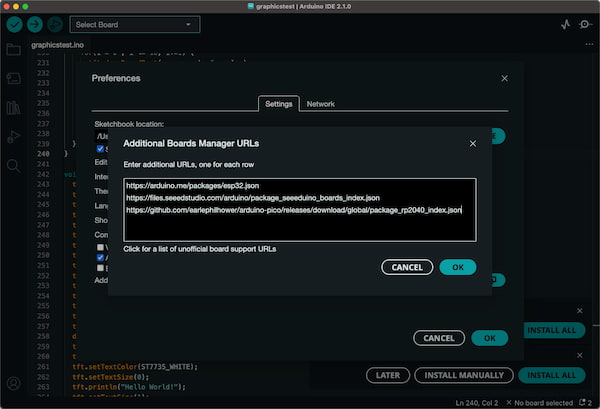
- I navigate to
Arduino IDE->Preferences(beacsue my recomputer is MAC), and fill Additional Boards Manager URLs with the url below:
https://github.com/earlephilhower/arduino-pico/releases/download/global/package_rp2040_index.json
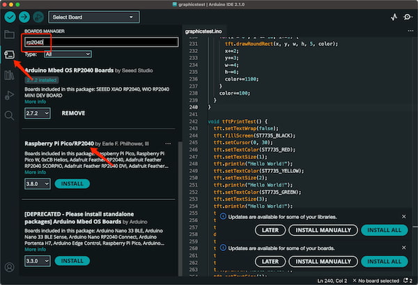
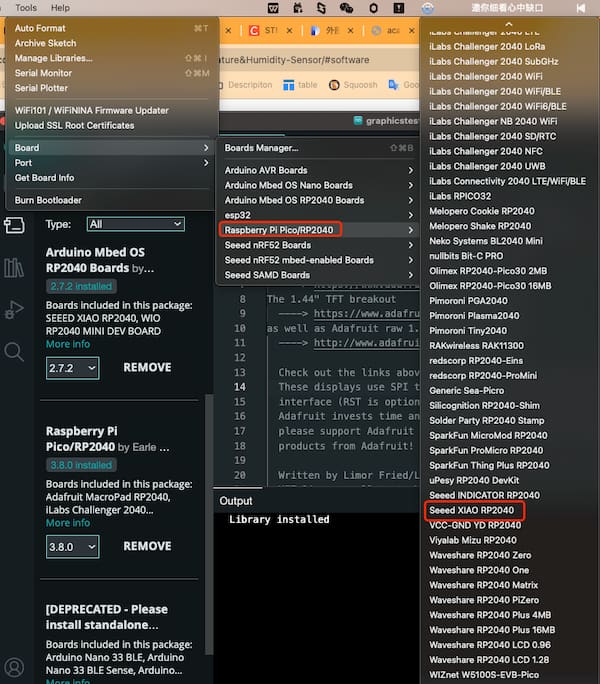
- I then navigate to the
Boards Manager..., type the keyword "RP2040" in the searching blank. Select the lastest version of "Raspberry Pi Pico/RP2040" and install it.
Libraries Setup
For using some components, there are additional Arduino libraries required(for using Arduino programming). I learnt that in this case, I need the additional libraries for both RGB light and Grove - AHT20 I2C Sensor:
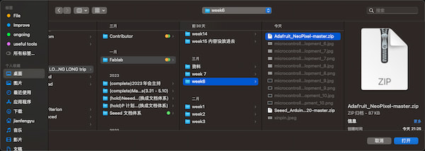
I download two .zip files and navigate to Sketch > Include Library > Add .ZIP library to search the library.
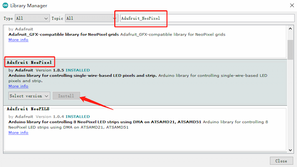
I can navigate to Sketch > Include Library > Manage Libraries... to search a library called Adafruit_NeoPixel to install the RGB library.
Now the hardware and software part are both done, I can get started.
Getting Started my project
I understood there are example codes, and I needed to rewrote them into one code to make RGB and Grove sensor working. And I want to achieve is that: The XIAO RP2040 will be used to control the RGB LED to change colors based on temperature readings from the Grove AHT20 temperature and humidity sensor.
- Less 22 degree: blue
- From 22 degree to 28 degree: green
- More than 28 degree: red
- The light should be flashable
I think the connection should be like:
It takes too much time to connect them with dupont wires (wires), and it's not good-looking. I aleady solder my XIAO RP2040 I don't want to solder anymore. And that's the XIAO Expansion board coming in:
Looks really nice. Then I can start my test, for checking the modules are functioning well:
I go to the the board selection and choose "Seeed XIAO RP2040" as I am ready to develop and test.
Grove AHT20 temperature and humidity sensor testing
From the Seeed example Wiki I find this code and I copy and upload to my XIAO RP2040 board:
// ARDUINO DEMO FOR GROVE-AHT20
//
#include <Wire.h>
#include "AHT20.h"

AHT20 AHT;

void setup()
{
    Serial.begin(115200);
    Serial.println("AHT20 DEMO");
    AHT.begin();
}

void loop()
{
    float humi, temp;

    int ret = AHT.getSensor(&humi, &temp);

    if(ret)     // GET DATA OK
    {
        Serial.print("humidity: ");
        Serial.print(humi*100);
        Serial.print("%\t temerature: ");
        Serial.println(temp);
    }
    else        // GET DATA FAIL
    {
        Serial.println("GET DATA FROM AHT20 FAIL");
    }

    delay(100);
}

// END FILE
After successfully uploading, I got the information here:
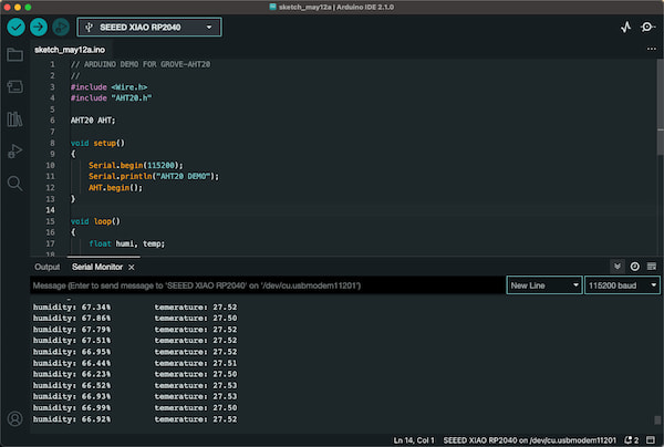
Then I know this sensor is working fine.
RGB light testing
From the Seeed example Wiki I find this code and I copy and upload to my XIAO RP2040 board.
#include <Adafruit_NeoPixel.h>

int Power = 11;
int PIN  = 12;
#define NUMPIXELS 1

Adafruit_NeoPixel pixels(NUMPIXELS, PIN, NEO_GRB + NEO_KHZ800);

void setup() {
  pixels.begin();
  pinMode(Power,OUTPUT);
  digitalWrite(Power, HIGH);

}

void loop() {
  pixels.clear();
  pixels.setPixelColor(0, pixels.Color(15, 25, 205));
  delay(400);
  pixels.show();
  pixels.clear();
  pixels.setPixelColor(0, pixels.Color(103, 25, 205));
  delay(400);
  pixels.show();
  pixels.clear();
  pixels.setPixelColor(0, pixels.Color(233, 242, 205));
  delay(400);
  pixels.show();
  pixels.clear();
  pixels.setPixelColor(0, pixels.Color(233, 23, 23));
  delay(400);
  pixels.show();
  pixels.clear();
  pixels.setPixelColor(0, pixels.Color(12, 66, 101));
  delay(400);
  pixels.show();
  delay(500);

}
Integration
So I did:
- Merge the contain declarations for both libraries.
- The initialization of AHT20 is put into the setup() function.
- A new setPixelColorWithFlash function was created to control the color change of NeoPixel and make the LED flash.
- In the loop() function, logic for the temperature reading is added to determine the color the LED should display.
- Updated NeoPixel's color setting code to display different colors based on temperature and flash.
The code is supposed to be:
#include <Adafruit_NeoPixel.h>
#include <Wire.h>
#include "AHT20.h"

int Power = 11;
int PIN  = 12;
#define NUMPIXELS 1

Adafruit_NeoPixel pixels(NUMPIXELS, PIN, NEO_GRB + NEO_KHZ800);
AHT20 AHT;

void setup() {
  Serial.begin(115200);
  Serial.println("AHT20 & NeoPixel DEMO");
  AHT.begin();
  pixels.begin();
  pinMode(Power,OUTPUT);
  digitalWrite(Power, HIGH);
}

void loop() {
  float humi, temp;
  int ret = AHT.getSensor(&humi, &temp);

  if(ret) { // GET DATA OK
    Serial.print("humidity: ");
    Serial.print(humi*100);
    Serial.print("%\t temperature: ");
    Serial.println(temp);

    // Different colors are displayed according to the temperature
    if(temp < 22) {
      // blue
      setPixelColorWithFlash(0, 0, 255, 255);
    } else if(temp >= 22 && temp <= 28) {
      // green
      setPixelColorWithFlash(0, 255, 255, 0);
    } else {
      // red
      setPixelColorWithFlash(255, 0, 0, 0);
    }
  } else { // GET DATA FAIL
    Serial.println("GET DATA FROM AHT20 FAIL");
  }

  delay(100); // sensing after 100ms
}

void setPixelColorWithFlash(uint8_t red, uint8_t green, uint8_t blue, uint8_t white) {
  pixels.clear(); // Turn off all pixels
  pixels.setPixelColor(0, pixels.Color(red, green, blue, white));
  pixels.show(); // Update the pixel color
  delay(400);
  pixels.clear();
  pixels.show();
  delay(400);
}
The final output:
Problem I faced
I ran this error before:
dyld: Symbol not found: _mkfifoat Referenced from: /Users/jianfengyu/Library/Arduino15/packages/rp2040/tools/pqt-python3/1.0.1-base-3a57aed/python3 (which was built for Mac OS X 14.2) Expected in: /usr/lib/libSystem.B.dylib
I search for the Google and I have found the reason that It is specified as a dependency by the "Raspberry Pi Pico/RP2040" boards platform 4 from Earle F. Philhower, III 2. The tool distribution is also provided by Earle Philhower.
I then ran these code:
$ ls -l /Users/jianfengyu/Library/Arduino15/packages/rp2040/tools/pqt-python3/1.0.1-base-3a57aed/python3
$ rm /Users/jianfengyu/Library/Arduino15/packages/rp2040/tools/pqt-python3/1.0.1-base-3a57aed/python3
$ ln -s "/System/Volumes/Data/opt/homebrew/bin/python3" "/Users/jianfengyu/Library/Arduino15/packages/rp2040/tools/pqt-python3/1.0.1-base-3a57aed/python3"