Input Voice into XIAO ESP32C3
Write something at the front
I want to develop a protable module for my personal assistant, helping me recording my daily words and enabling to connect the assistant. I here design the initial model.
I need to configure the audio input settings in the code:
- Specify the sample rate, bit depth, and number of channels (usually mono for speech recognition).
Hardware I am going to use
I am going to use the hardware below:

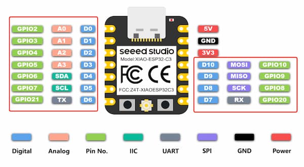
Why I am using XIAO ESP32C3 is that it can offer wireless connectivity(Wi-Fi/Bluetooth) and it is good for my final project, as well as it is powerful enough to drive multiple images display.
XIAO ESP32C3
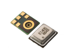
And an MEMS microphone, SPH0645 type, SPH0645LM4H as specific:
I have searched for some information about I2S MEMS microphone and this Youtuber atomic14 is introducing well.
Notes about MEMS microphones(SPH0645 and INMP441)
Both SPH0645 and INMP441 are assembled with Micro-electromechanical Systems and integrating audio amplifier, ADC, connecting under the I2S protocol.
- They are no ADC required for connecting ESP32 board -> This is really good.
This is well packed, and containing a hole in the bottom for the sound to enter.
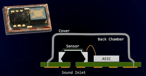
The principle of they working is simliar to the Electret Microphone with a capacitor that changes value due to air pressure.
And this is the connection:
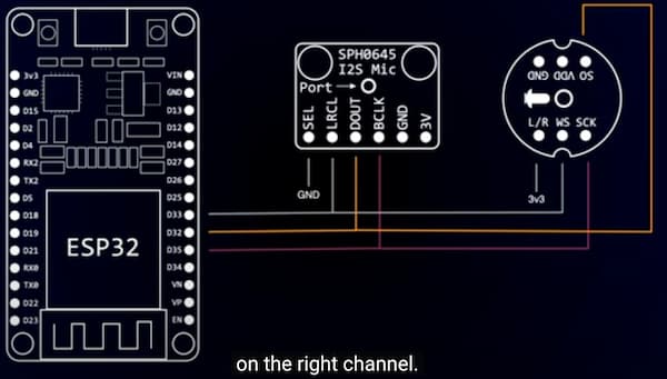
And the principle of the connection(the names confuse me a little before):
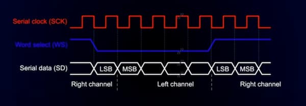
BCLK(Bit Clock) : This interface is the same in both descriptions and is used to provide the clock signal in I2S communication.DATAandDOUT: These two terms actually refer to the same signal, data output. DATA, which may be referred to asDOUTin some documents, refers to the digital audio data output from the microphone to the master controller.WSandLRCL: These two terms are also the same signal, i.e. "Word Select" or "Left/Right Clock". This signal is used to indicate whether left or right channel data is being transmitted.
For choosing differernt side audio, using this code: .channel_formal = I2S_CHANNEL_FMT_RIGHT_LEFT, high level is left and low level is right.
The INMP441 type microphone is recommended as the YouTuber said, it produces a good signal with no DC offset.
The ongly problem is there is no built-in AGC(Automatic Gain Control) -> But it is good and enough for my project.
There is another audio tools GitHub repo he recommended: Arduino Audio Tools.
Something about I2S on XIAO ESP32C3
I found there all GPIO pins are supporting I2S connection, but only contains one I2S peripheral. These are two concepts:
All pins support I2S: This means that most of the GPIO pins of the ESP32C3 can be software-configured to be used as individual signals for the I2S interface (e.g. BCLK, WS, DATA). The ESP32C3's flexibility lies in its GPIO matrix, a feature that allows most GPIO pins to be configured to support different functions, including I2S. Such a design provides greater freedom to choose a pin layout that suits the needs of a particular project.Only 1 I2S peripheral included: This indicates that there is only one I2S controller or hardware module inside the ESP32C3 chip. Although there is only one I2S controller physically, I can connect it to multiple different GPIO pins through software configuration. This means that I just can't configure multiple independent I2S interfaces at the same time, because all I2S signals need to be processed by this one I2S controller.
Updated on Seeed Studio Forum, the users are applying 2,3,4 to enable I2S.
As far as ensuring that the selected GPIO pin is available on the XIAO ESP32C3 development board and is not occupied by other immutable uses such as power, grounding, or dedicated functions, I can do the I2S connection.
Software Development(Arduino)
Thanks to DroneBot Workshop and his detailed wiki, I have learnt the code for connecting INMP441 to my XIAO ESP32C3:
And according my connection and previous knowledge, I need to change the code and upload it, but there are no response. One problem is the connection lost and one is the Arduino problem for board misled.
The important issus are that:
Microphone sensitivity: In the loop() function of the code, therangelimit = 3000is adjusting the sensitivity. If this value is set too high, it may result in no output in a quiet environment. Try to lower this value and it will become ok.- And there should be enough flash and resource to enable the code, by selecting this option for XIAO ESP32C3:
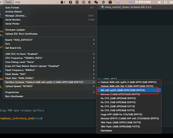
This will be the best.
Eventually, the code is:
/*
  ESP32 I2S Microphone Sample
  esp32-i2s-mic-sample.ino
  Sample sound from I2S microphone, display on Serial Plotter
  Requires INMP441 I2S microphone

  DroneBot Workshop 2022
  https://dronebotworkshop.com
*/

// Include I2S driver
#include <driver/i2s.h>

// Connections to INMP441 I2S microphone
#define I2S_WS 9
#define I2S_SD 10
#define I2S_SCK 8

// Use I2S Processor 0
#define I2S_PORT I2S_NUM_0

// Define input buffer length
#define bufferLen 64
int16_t sBuffer[bufferLen];

void i2s_install() {
  // Set up I2S Processor configuration
  const i2s_config_t i2s_config = {
    .mode = i2s_mode_t(I2S_MODE_MASTER | I2S_MODE_RX),
    .sample_rate = 44100,
    .bits_per_sample = i2s_bits_per_sample_t(16),
    .channel_format = I2S_CHANNEL_FMT_ONLY_LEFT,
    .communication_format = i2s_comm_format_t(I2S_COMM_FORMAT_STAND_I2S),
    .intr_alloc_flags = 0,
    .dma_buf_count = 8,
    .dma_buf_len = bufferLen,
    .use_apll = false
  };

  i2s_driver_install(I2S_PORT, &i2s_config, 0, NULL);
}

void i2s_setpin() {
  // Set I2S pin configuration
  const i2s_pin_config_t pin_config = {
    .bck_io_num = I2S_SCK,
    .ws_io_num = I2S_WS,
    .data_out_num = -1,
    .data_in_num = I2S_SD
  };

  i2s_set_pin(I2S_PORT, &pin_config);
}

void setup() {

  // Set up Serial Monitor
  Serial.begin(115200);
  Serial.println(" ");

  delay(1000);

  // Set up I2S
  i2s_install();
  i2s_setpin();
  i2s_start(I2S_PORT);


  delay(500);
}

void loop() {

  // False print statements to "lock range" on serial plotter display
  // Change rangelimit value to adjust "sensitivity"
  int rangelimit = 1000;
  Serial.print(rangelimit * -1);
  Serial.print(" ");
  Serial.print(rangelimit);
  Serial.print(" ");

  // Get I2S data and place in data buffer
  size_t bytesIn = 0;
  esp_err_t result = i2s_read(I2S_PORT, &sBuffer, bufferLen, &bytesIn, portMAX_DELAY);

  if (result == ESP_OK)
  {
    // Read I2S data buffer
    int16_t samples_read = bytesIn / 8;
    if (samples_read > 0) {
      float mean = 0;
      for (int16_t i = 0; i < samples_read; ++i) {
        mean += (sBuffer[i]);
      }

      // Average the data reading
      mean /= samples_read;

      // Print to serial plotter
      Serial.println(mean);
    }
  }
}
And the output is like:
The code part is done.
Design PCB on the KiCAD
What I want to achieve is that when I power the board up or put a switch on, this module can record my words and then transmit them as a audio file. And at the same time, I have to consider what display that I might have, to show the connection with reComputer.
Thus, for my input PCB design board, I will have one INMP441 onabord, and two Conn PinHeader1x03 P2.54mm Horizontal SMD for connecting RGB displays.
Finally, I have to find a way to fix it, thus I might need some holes.
I directly called the KiCAD file including INMP441 design on this GitHub. I download it and duplicate its design on my PCB, only the INMP441 part.
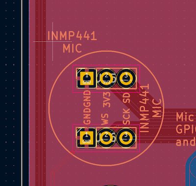
I am using Conn PinHeader1x03 P2.54mm Horizontal SMD to replace his PCB design.
And I want to input XIAO-ESP32C3_SocketSMD for holding a battery in the future.
For some points, I am thinking the Grove Connecotor for connecting RGB display.
And the holes, for holding of course. Eventually I have this version
Later I think I might need more RGB displays, or have backup connections. And the most important thing is that the holes are not supposed be outsides.
I should reconsider it. Thus, for updates:
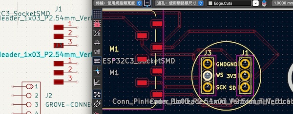
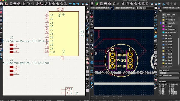
I add two more Conn_PinHeader_1x03_P2.54mm_Horizontal_SMD, and here is the final schematic diagram:
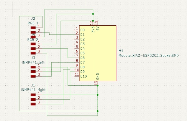
For making connection more easier:
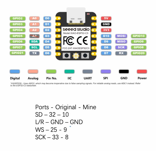
- I make some changes about the connection. Giving any GPIO on ESP32 can be I2S, I switch
WSto9,SCKto8, andSDto20. - And I add two PinHeader connecting signal pin to
3and21.
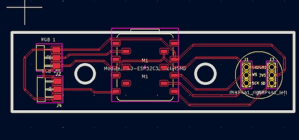
And this will be the final PCB looking:
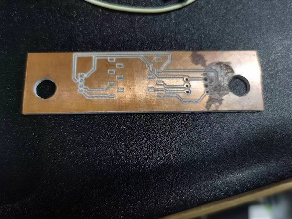
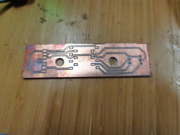
Milling...
There is the board:
And after soldering:
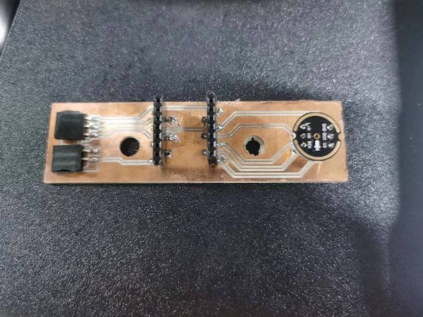
This is why I should have backups...
Function Check
Anyway, the board is done and I can check the output:
Just make sure I switch WS to 9, SCK to 8, and SD to 20.
(test) Software Development(MicroPython)��
For some reasons, I think the MicroPython is not suppporting I2S cause it keep output:
File "<stdin>", line 2, in <module>
ImportError: can't import name I2S
Update on 6.10th
Here is some solution, a library built by ricksorensen:
https://github.com/micropython/micropython/issues/8641
But I think I need to esptool to flash it:
- Download the tool with:
pip install esptool
and use this command to burn the file into the board:
esptool.py --chip esp32 --port /dev/ttyUSB0 --baud 115200 write\_flash -z 0x1000 <path to bin file>
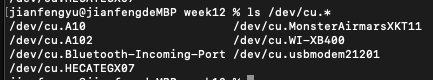
The /dev/ttyUSB0 can use command ls /dev/cu.* to find it:
For the flash code, the pip install esptool adafruit-ampy should be installed as well.
Then can use this code to flash the python file into the board:
ampy --port <port> put <code.py>
The screen display of port is:
screen <port> 115200
Software Testing(ESP-IDF)
For the example(I2S to ESP32 Chip), it is recommended to use ESP-IDF to do the work. And I will have reCOmputer Jetson(Linux) to do the development, it is needed.
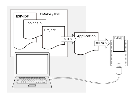
ESP-IDF is the official development framework for the ESP32, ESP32-S, ESP32-C, ESP32-H and ESP32-P Series SoCs, designed by ESPRESSIF company and here is the guide.
And this is the principle:
Installation of ESP-IDF
Thanks Citric's Wiki from Seeed(Developed on XIAO using Espressif ESP-IDF), I have the steps to install the ESP-IDF:
Step 1. Install Prerequisites
Ensure the latest packages and dependencies. Open a terminal and run the following commands:
sudo apt update
sudo apt upgrade
Here is the code to download all the dependences:
sudo apt-get install git wget flex bison gperf python3 python3-pip python3-venv cmake ninja-build ccache libffi-dev libssl-dev dfu-util libusb-1.0-0
CMake version 3.16 or newer is required for use with ESP-IDF. Run "tools/idf_tools.py install cmake" to install a suitable version if your OS versions does not have one.
Step 2. Installing Python3
There is pre-install Python3 in the reComputer so I can skip this part.
Step 3. Get ESP-IDF
To get ESP-IDF, navigate the installation directory and clone the repository with git clone. Open Terminal, and run the following commands:
mkdir -p ~/esp
cd ~/esp
git clone -b v5.2.1 --recursive https://github.com/espressif/esp-idf.git
By executing the above command, ESP-IDF will be downloaded to ~/esp/esp-idf.
Step 4. Set up the Tools
Aside from the ESP-IDF, I need to install the tools used by ESP-IDF, such as the compiler, debugger, Python packages, etc, for projects supporting ESP32.
cd esp-idf/
./install.sh
Step 5. Set up Environment Variables
The installed tools are not yet added to the PATH environment variable. To make the tools usable from the command line, some environment variables must be set. ESP-IDF provides another script which does that.
In the terminal where I am going to use ESP-IDF, run:
source ./export.sh
cd ..
For every time I use, I should run this commend.
This is the version checking:
idf.py --version
Running the LED Example Program for testing
To ensure that my ESP-IDF environment is set up correctly, I can run a LED example for XIAO ESP32C3 board.
Step 1. Connect my XIAO ESP32C3 to reComputer
I connect my XIAO ESP32C3 to my reComputer and use this commend /dev/tty to check the ports:
I find the extra one(different one) is /dev/ttyACM0 and this should be it.
Step 2. Start a Project
Navigate to the examples directory
cd ~/esp/esp-idf/examples/get-started/blink
Set the target device.
idf.py set-target esp32c3
I use this commend to determind the port of the LED, and I can modify various settings.
idf.py menuconfig
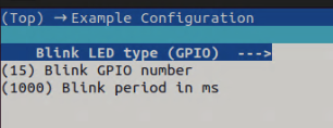
Taking the blink project as an example, there are three parameters that can be adjusted.
- Blink LED type: Set the type of LED to use, in this case we set it to GPIO.
- Blink GPIO number: The GPIO pin number where the LED is located is set to 15 here, I can adjust it.
- Blink period in ms: The time interval between light flashes. The default is 1000 milliseconds, or 1 second.
Once the setting is complete, press q to exit the setup menu and then y to confirm the changes.
Step 3. Build and Flash the Example
Build the project by running:
idf.py build
This command compiles the application and all ESP-IDF components, then it generates the bootloader, partition table, and application binaries. If there are no errors, the build finishes by generating the firmware binary .bin files.
I then run this code to flash:
idf.py -p /dev/ttyACM0 flash
There is an error when uploading that shows: dev/ttyACM0 not readable. And this is usually caused by a lack of authority. On Linux systems(reComputer), access to serial device files such as /dev/ttyACM0 is usually limited to a specific group of users.
Hence, using this command
sudo usermod -a -G dialout $USER
to fix it.
And then using ls -l /dev/ttyACM0 to check the information and it shows up like this:
crw-rw---- 1 root dialout 166, 0 May 1 12:34 /dev/ttyACM0
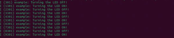
To view the output of the LED example program, run the following command
idf.py monitor
The monitor will be showing LED on XIAO blinking, indicating that the example program is running successfully.
Then I use the shortcut Ctrl+]to quit the monitor.
There are more commands in the ESP-IDF environment:
idf.py menuconfig: Opens the project configuration menu.idf.py build: Builds the project.idf.py flash: Flashes the built firmware to the connected device.idf.py monitor: Starts the serial monitor to view the output from the device.idf.py clean: Cleans the build directory.idf.py fullclean: Performs a full clean, including the downloaded dependencies.idf.py set-target: Sets the target chip for the project.idf.py size: Displays the size information of the built firmware.idf.py app: Manages applications in the project.idf.py component: Manages components in the project.
This is for the future usage: put the audio file into a SD card and save it as long as possible.