Group Assisnment Week 12
In this week, I am going to:
- Probe an input device(s)'s analog levels and digital signals
- Document my work on the group work page and reflect on my individual page what you learned
Information about Oscilloscope and Signal Generator
We have one Dual Channel Function Signal Generator in the lab:
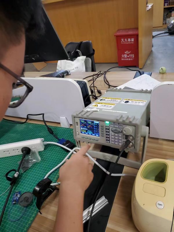
This device can generate 40mHz ~ 25MHz signal, with 100MSa/s.
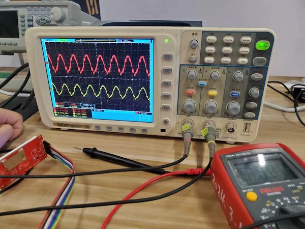
And this is the Oscilloscope we are using and the function seems ok:
Sense the signal from DHT11 sensor
I am using DHT11 sensor to check the signal and applying channel 1. Here is the connection:
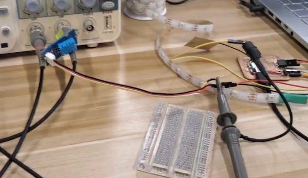
Actually this is my teammate, Dion's final project and this is her board:
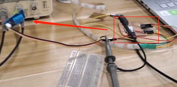
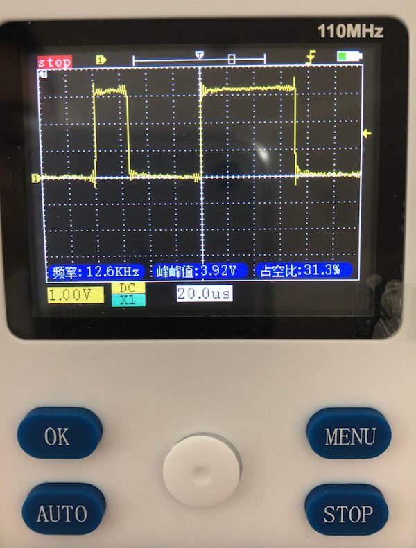
Then after connecting the both sides for sensing. We got the results:
Every time I need to make sure that the grounding wire of the measuring probe (usually the black wire or grounding clip on the oscilloscope probe) is properly grounded when making an oscilloscope measurement. This is to avoid signal interference or electrical noise, but also to be on the safe side. Proper grounding can help obtain a clearer and more accurate signal waveform.
Then this should be the actual signal output: