Electronics Design
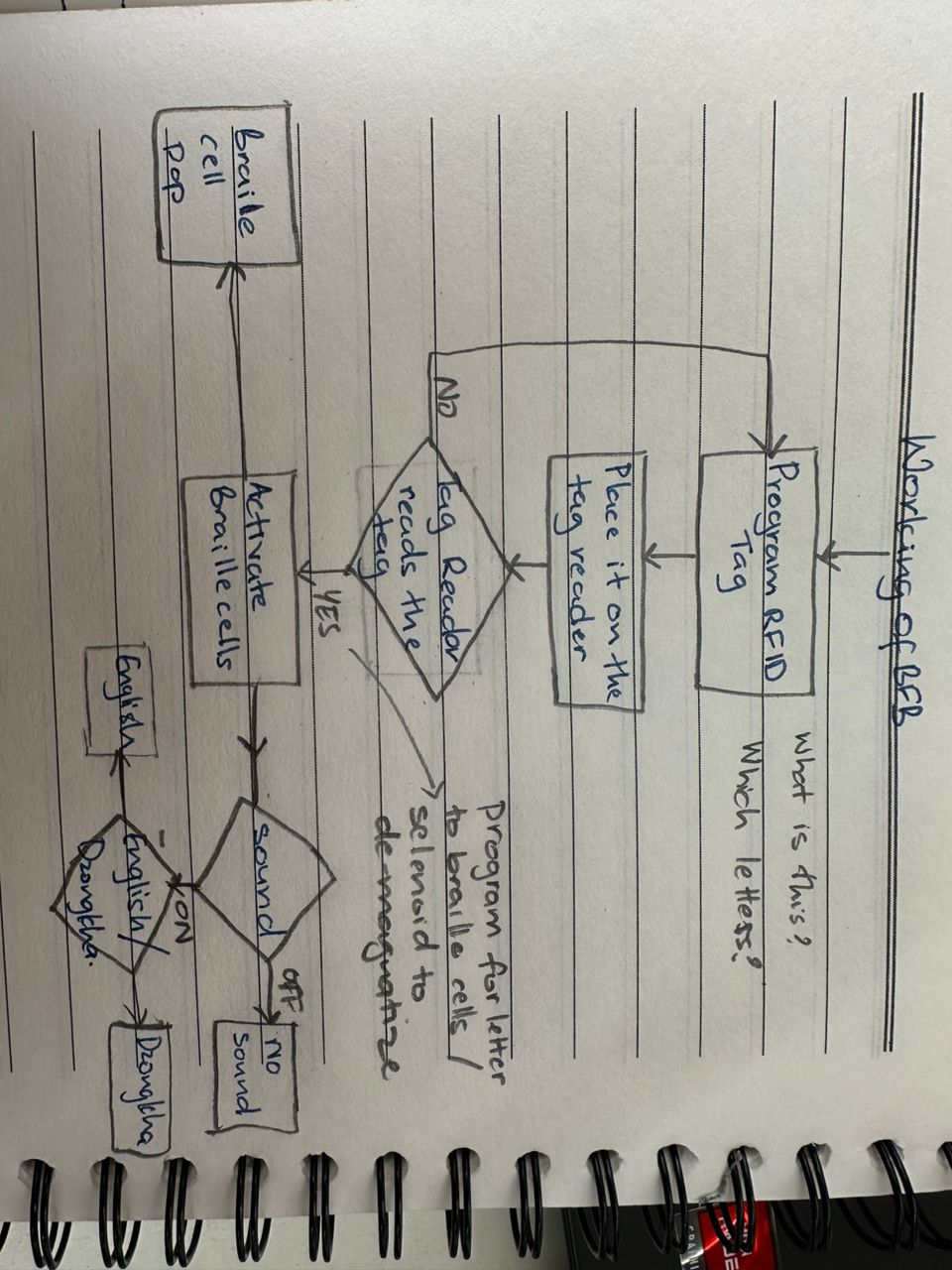
Working
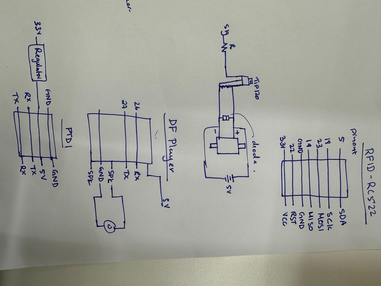
Planned Pinouts
First Attempt
My first board failed. I was too ambitious and was trying to make my final board. In the process I forgot to add reset button and also from FTDI cablel, forgot to put in a voltage regulator.
-
Using a jumper wire I could solve the power problem by removing the power from FTDI cable but because I did not have a reset button, I was not able to program the board.
-
Also somehow I forgot to route the button to enable pin anded used jumper wire to program. I also did my pin connections wrong for the RFID.
But my power source from Power jack worked.

Output and Input devices Considered
- 6 Selenoids
- Speaker through DFplayer Mini(GND, IN, VCC)
- RFID tag reader(7 pins, SDA,SCK,MOSI,MISO,GND,RST,VCC)
- Switches
- LEDs
- FTDI programming pins
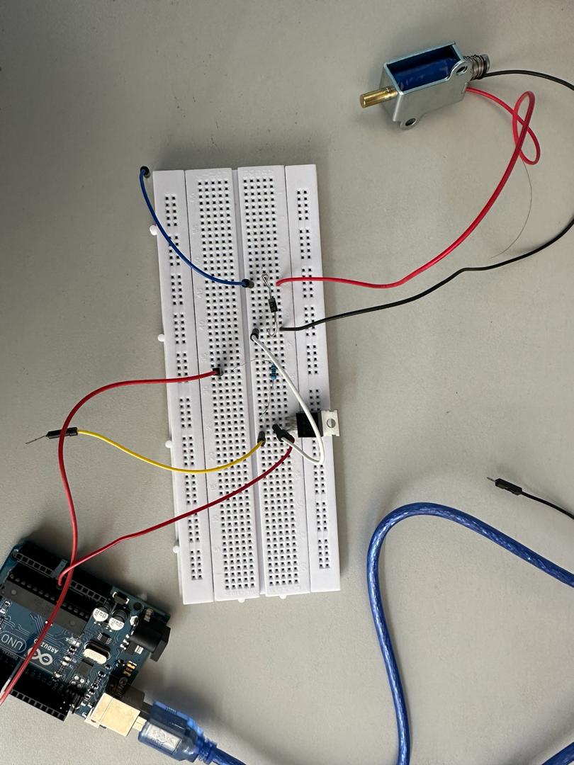
Selenoid Testing
Tested 12V solenoid that was in the lab but need to test 5V solenoid. The testing of solenoid with relay is already explained in the output week. Using transitor to switch the solenoids was also an option I wanted to explore as the relays were bulky.
I used the IRF830 for this testing as this was the only switching MOSFET we had in the lab. It works only when 13 Volts in suppled and I think that is because Drain-Source resistor is 1.5 Volts.
Features
- N-Channel Power MOSFET
- Continuous Drain Current (ID): 4.5A
- Gate threshold voltage (VGS-th) is 10V (limit = ±20V)
- Drain to Source Breakdown Voltage: 500V
- Drain Source Resistance (RDS) is 1.5 Ohms
- Rise time and fall time is 16nS and 16nS
- Available in To-220 package
For the final project, I will be using TIP120 darlinton-Transistor with 5 volts solenoid.
Solenoid Testing and programming
I tried programming RFID using ESP-32 Dev module and relay modules to check if my programming was working. I did two programming and the second version worked.
- I renamed the 2nd block of each RFID card as A , B and C.
- Secondly, programmed ESP32 module to swicth on the related solenoid to pop braille letters.
My code worked, so now I need to futher develop the the code for all the letters and numbers for future.
Here are my codes:
Second attempt
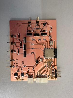
For this week 13 assignment, I made a new board for my final project. I designed the board after testing my program in a ESP32 dev module in my previous assignment. I used the RFID Card that I programmmed in previous weeks assignment with letters to pop corresponding solenoids when placed on card reader this week.
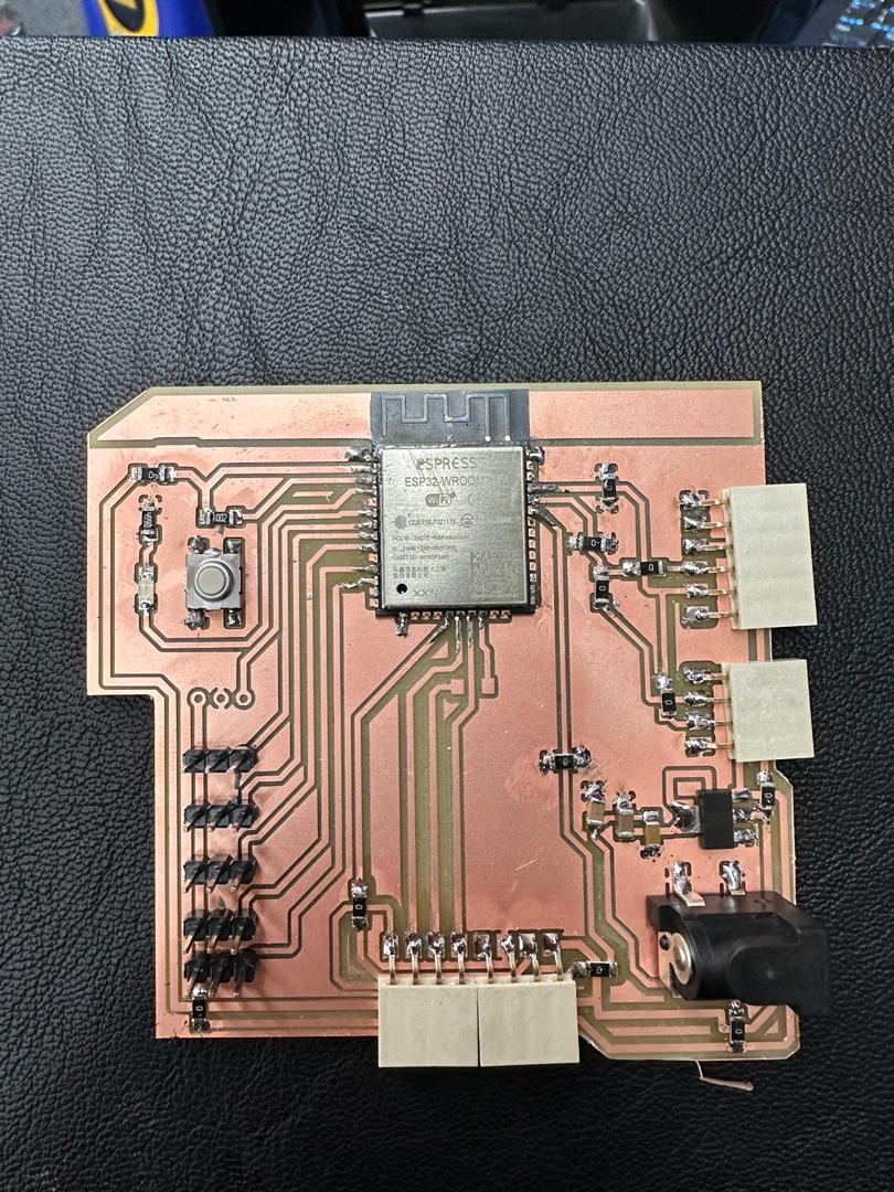
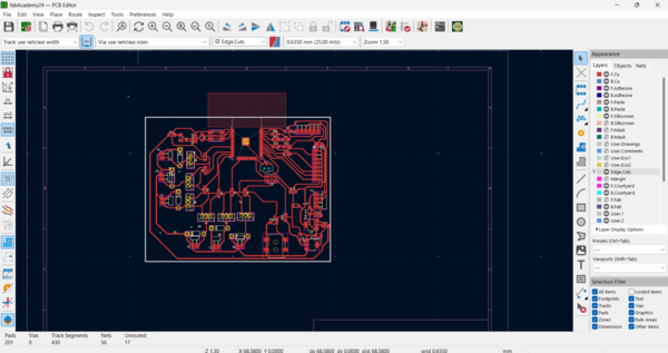
I used KiCAD to desing my board as shown below.
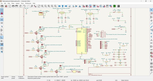 (This is the corrected ckt with the right orrientation of the power jack and power supply of FTDI cable)
Failure
I had to mill two boards as in the first one I had inverted the SVG image of drill files in MODs, which made the drill holes bigger.

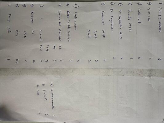
Here are the BOM:
-
Also the the board below, the orrientation of the power jack was wrong in my design because of which I had power issue in my board. I had also connected, 3 volts output of the regulator to 5 volts input of FTDI cable.
-
With few tweaks I was able to use the board by giving the power supply from board external powersupply and not using the input powersupply from ftdi cable.(I corrected the ckt and attached above)
-
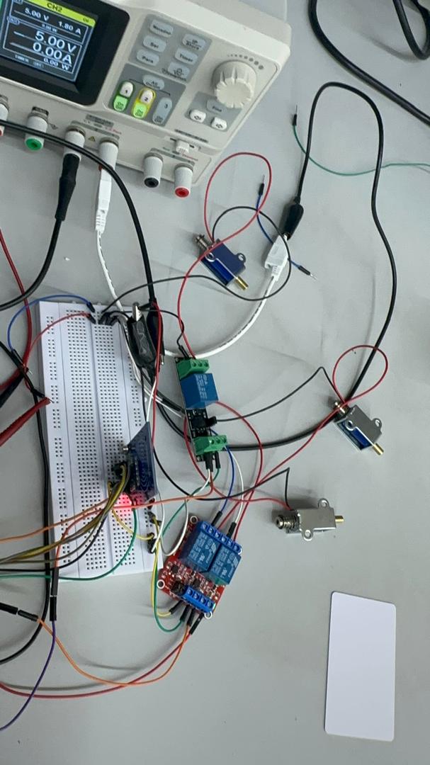
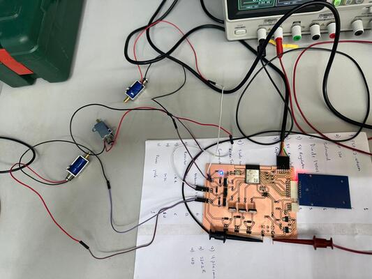
Here is the setup for my this weeks assignment. I gave an input power supply of 12V from a power source with 1.8A current.
-
The pin connections for RFID card reader are as follows: SDA-22, CLK-19, MOSI-23, MISO-25, GND-GND, RST-22, 3.3V-3.3V. For solenoid, I connected the solenoids to GPIO27, GPIO25 and GPIO14.
-
The had already programmed the cards in week 11 for the input week and this week I want the card reader to read the card
-
I wrote the program with help from online tools and Claude AI chat bot which was much more helpful then ChatGPT.
-
I am attaching the full code below but here is the logic to the code which triggered the respective solenoids when the card reads the last data on the RFID card. I wanted to trigger particular solenoids as they will be my braille cells for my final project.
void displayBraillePattern( char letter)
{
  switch (letter)
  {
    case 'A':
      Serial.println("Case A");
      digitalWrite(SOLENOID1_PIN, HIGH);
      digitalWrite(SOLENOID2_PIN, LOW);
      digitalWrite(SOLENOID3_PIN, LOW);
      break;
    case 'B':
      Serial.println("Case B");
      digitalWrite(SOLENOID1_PIN, HIGH);
      digitalWrite(SOLENOID2_PIN, LOW);
      digitalWrite(SOLENOID3_PIN, HIGH);
      break;
     case 'C':
      Serial.println("Case C");
      digitalWrite(SOLENOID1_PIN, HIGH);
      digitalWrite(SOLENOID2_PIN, HIGH);
      digitalWrite(SOLENOID3_PIN, LOW);
      break;
    // Add more cases for other letters here
    default:
      Serial.println("Default");
      digitalWrite(SOLENOID1_PIN, LOW);
      digitalWrite(SOLENOID2_PIN, LOW);
      digitalWrite(SOLENOID3_PIN, LOW);
      break;
  }
  delay(1000); // Adjust the delay as needed
  digitalWrite(SOLENOID1_PIN, LOW);
  digitalWrite(SOLENOID2_PIN, LOW);
  digitalWrite(SOLENOID3_PIN, LOW);
}
The code worked and you can see in the video below:
!!! Failure Brownout detector was triggered
I got this error with the new board I made for this week and I could not figure out the error. I said it was because of the bad connection(soldering issue) and power issue but even when measuring the the input voltage it was 3 volts. So, I used my other board I made in previous week which worked. I need to still check remake the board and maybe that time it wll work.