OutPut Devices
| Task | progress |
|---|---|
| Demonstrate workflows used in controlling an output device(s) with MCU board you have designed. | done |
Group Assignment
Here is the link to this weeks Group Assignment.
Key takeaways from this week:
- Connect multimeter in parallel for measuring voltage and to measure current, connect multimeter in serial ALWAYS
Output Devices
I had alread tried few output devices prior to this week like the OLED and Servos in Embedded week. Here
Learing from this week:
-
Need to calculat the load(Current, voltage , power) for all the output devices and design power supply for the board.
-
Need to study the GPIO pins of the MCU as I realized that the pin as some of the pin in ESP32 are just input pins and not output.
Solenoid
I decided to work with selenoid this week as I will be using it for my final project. Becacuse I only had 12 volts selenoid I had to use a relay for external powersupply. I used the board I designed last week.
Hero Shot
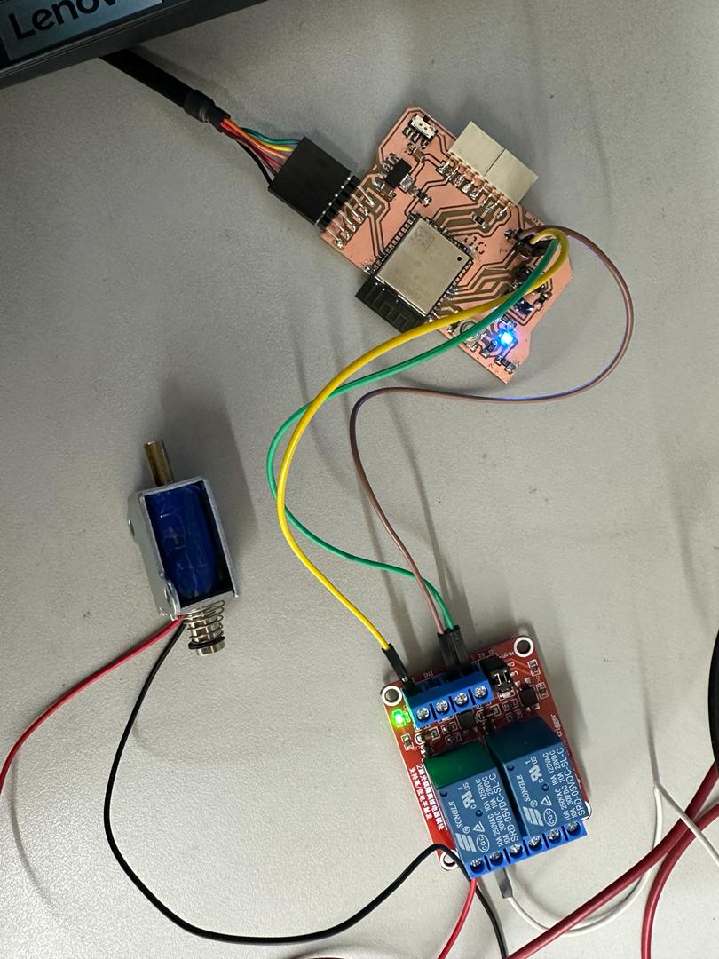
I provided an external power supply of 12 volts to the relay and connected the solenoid to NO pin (Normally closed). The relay I used takes in 2 inputs so connected the VCC, GND and GPIO32 to IN1 pin of relay.
const int relayPin = 32; // GPIO pin connected to the relay module

void setup() {
  pinMode(relayPin, OUTPUT);
}

void loop() {
  // Switch on the solenoid
  digitalWrite(relayPin, HIGH);
  delay(1000); // Solenoid remains ON for 1 second

  // Switch off the solenoid
  digitalWrite(relayPin, LOW);
  delay(5000); // Solenoid remains OFF for 5 seconds
}
LEDs
I wanted to try CharliePlexing for this week and learn how I can use fewer pins to manuplate several output devices. In my case 6 LEDs. I took reference from this youtube link and also this page but in this page the ckt diagram is not complete as it didn’t work.
For charlieplexing this is the rule that has to be followed n(n-1)= number of output device it can control, where n is the number of pins. In my case n=3 can control 6 outputs.
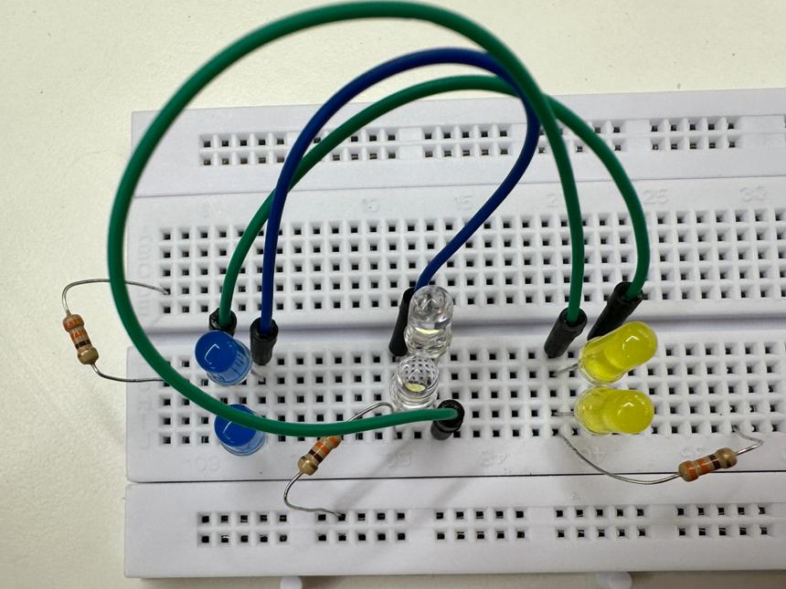
I used Quentoris board that I had made in electronics production week. Modified the code below, that I got from the above link for Xiao Rp2040 and uploaded the code using Arduino IDE.
const int LED_1 = 1;     //LED row 1
const int LED_2 = 2;     //LED row 2
const int LED_3 = 4;     //LED row 3

void setup()
{
}

void loop()
{
  //turn on LED L1
  pinMode(LED_1, OUTPUT);     //row 1
  digitalWrite(LED_1, LOW);
  pinMode(LED_2, OUTPUT);     //row 2
  digitalWrite(LED_2, HIGH);
  pinMode(LED_3, INPUT);      //row 3
  digitalWrite(LED_3, LOW);

  delay(1000);

  //turn on LED L2
  pinMode(LED_1, OUTPUT);     //row 1
  digitalWrite(LED_1, HIGH);
  pinMode(LED_2, OUTPUT);     //row 2
  digitalWrite(LED_2, LOW);
  pinMode(LED_3, INPUT);      //row 3
  digitalWrite(LED_3, LOW);

  delay(1000);

  //turn on LED L3
  pinMode(LED_1, INPUT);      //row 1
  digitalWrite(LED_1, LOW);
  pinMode(LED_2, OUTPUT);     //row 2
  digitalWrite(LED_2, LOW);
  pinMode(LED_3, OUTPUT);     //row 3
  digitalWrite(LED_3, HIGH);

  delay(1000);

  //turn on LED L4
  pinMode(LED_1, INPUT);     //row 1
  digitalWrite(LED_1, LOW);
  pinMode(LED_2, OUTPUT);    //row 2
  digitalWrite(LED_2, HIGH);
  pinMode(LED_3, OUTPUT);    //row 3
  digitalWrite(LED_3, LOW);

  delay(1000);

  //turn on LED L5
  pinMode(LED_1, OUTPUT);    //row 1
  digitalWrite(LED_1, LOW);
  pinMode(LED_2, INPUT);     //row 2
  digitalWrite(LED_2, LOW);
  pinMode(LED_3, OUTPUT);    //row3
  digitalWrite(LED_3, HIGH);

  delay(1000);

  //turn on LED L6
  pinMode(LED_1, OUTPUT);
  digitalWrite(LED_1, HIGH);
  pinMode(LED_2, INPUT);
  digitalWrite(LED_2, LOW);
  pinMode(LED_3, OUTPUT);
  digitalWrite(LED_3, LOW);

  delay(1000);
}