3d scanning and printing
| Task | progress |
|---|---|
| Linked to the group assignment page | done |
| Explained what you learned from testing the 3D printers | done |
| Documented how you designed and 3D printed your object and explained why it could not be easily made subtractively | done |
| Documented how you scanned an object | done |
| Included your original design files for 3D printing | done | Uploaded your source code | done |
| Included your hero shots Explained any problems and how you fixed them | done |
| Included your hero shots Explained any problems and how you fixed them | done |
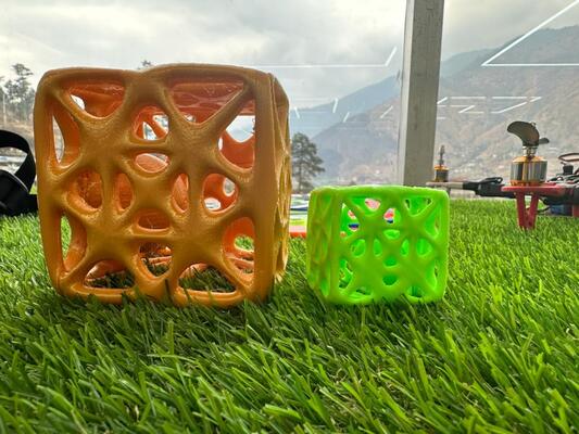
Hero shot
Group Assignment
Link to group assignment is here
This week we learned about 3d printing and scanning.
3d Printing
d printing is known as additive manufacturing, is a process of creating three-dimensional objects from a digital model by laying down successive layers of material until the object is formed.
3d printing is an *additive manufacturing process where material is added layer by layer to create final product. Unlike is Substractive manufactuing like Milling, does not take out material to form object.
Few advantages: - Desing flexibiltiy - Material effiecient + cost efficient - Allows customization - Rapid prototyping
Disadvantages:
- Build size limitation
- Mass production
- Post desing requirements
- Material limitation
We have Prusai3 MK3S printer which is a very good printer with all the extra features of auto resume and crash detection and also auto bed leveling. It is an open source design.
I used an Ender-3 pro printer before and there is a huge difference in using these two differnt printer. Prusa is very user friendly.
Observation: - In the bridge test, we could observe overhang in 20mm length. - String can also be seen and this can be controlled through controlling the temperature. - The Pruse printed looks rough compared to formlabs.
3d Scanning
3d Scanning
“3D scanning involves using specialized hardware to capture the geometry and appearance of an object or environment. There are various types of 3D scanning technologies, including laser scanning, structured light scanning, and contact scanning.”
Using Artect Eva 3d scanner
We have Artect Eva 3d scanner which needs a Computer with high GPU. “This scanner utilizes structured light technology where it projects a pattern of ligh onto the surface of the object being scanned and then using cameras to capture images of the object with the projected pattern. By analyzing how the pattern distorts on the object.”
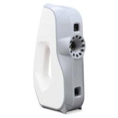 picture from web
Key features of the scanner:
-
16 FPS capturing speed: Capturing and simultaneously processing up to an impressive 18 million points per second, Eva also provides high accuracy — up to 0.1 mm.
-
0.2 mm 3D resolution: Scan in brilliant color and high 3D resolution.
-
1.3 MP texture resolution: Make full-color 3D replicas of your object.
This scanner can scan upto small to meduim object.
Personally, I found it very hard to use this scanner as we need to hold the scanner very steady and also move slowly. Because of which I didn’t get a perfect scan with Artect Eva.
First, I tried scanning my water bottle. I used a rotating stool for comfortable scanning and it was found that it is better to do it this was as I am able to get more stabilty.
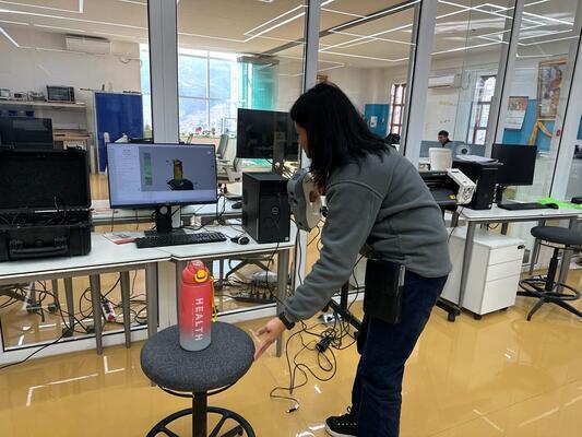
But unfortunately, I was not able to can the lid properly as I was losing the track constantly while moving the scanner upper to capture the lid.
I used Autopilot tool in Artect studio application for the scanner for automatic edition and model creation.
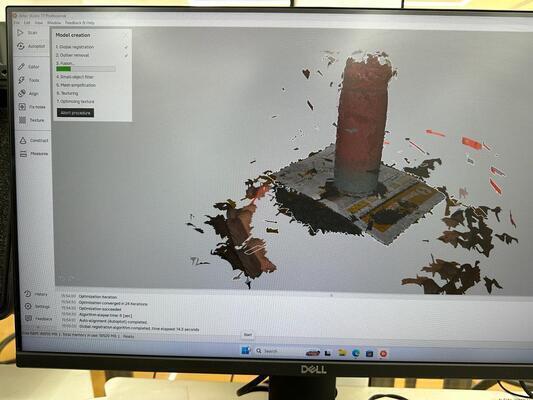
I decided to change the model after several tried and went with a trophy which was smaller and had less shine.
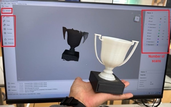
After scanning, I used autopilot to model. And also used the the tools on the right side to fix the model, like the edit tool, to erase the extra features that got scan.
Also used, fix hole feature to fill in the gaps that was not scanned.
Align also helps to combine different scans togerther to make one model in which each scan make up for each other.
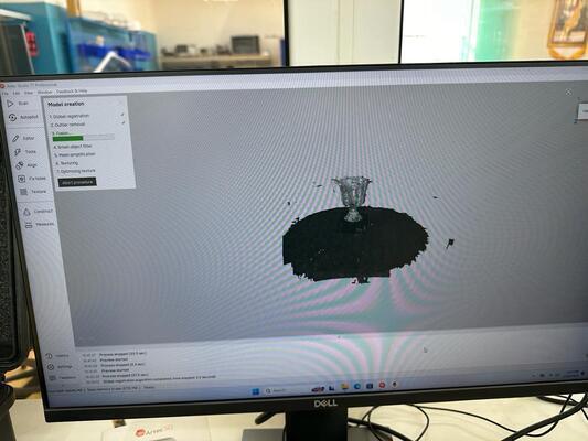
On the left side, you can see the number of scan I did and tried. Because the tropy was hollow, the scan was creating weird structurs on the top. Also because the handle was thin, the scanner was not capturing it properly. I also assume, because of shinny, and reflective floor, it was creating this problem with the scan.
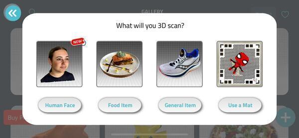
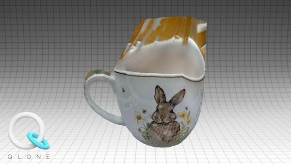
Qlone
This is a moble app for scanning using photogrametry.
Photogrammetry
“Photogrammetry is a technique that involves taking multiple overlapping photographs of an object or environment from different angles and using software to analyze the images and reconstruct a 3D model. Here’s how it typically works: “
I found this app much more easier. But this app depened on the type of object we are trying to scan.
Limitation of this app is:
-
It is not free for all features
-
It can only scan small objects.
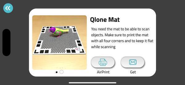
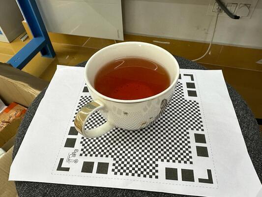
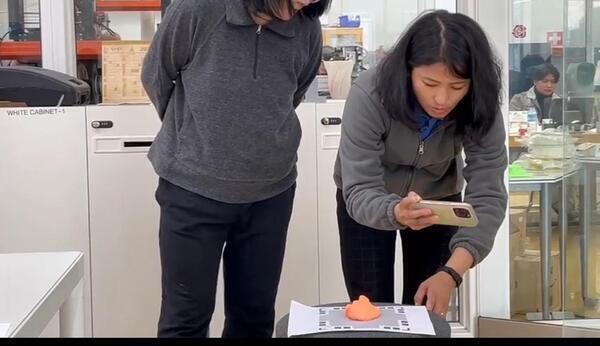
After donwloading the app, I downloaded the Mat as this was the only free feature avaliable and printed the mat. We need the mat during as we have to place the object to be scanned on the mat as seen in the picture below.
Tried scanning a shinny object, my mug which had black tea.
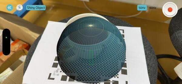
After, placing the object on the mat and when we click play, a dome appears on the app as we move closer to the mat.
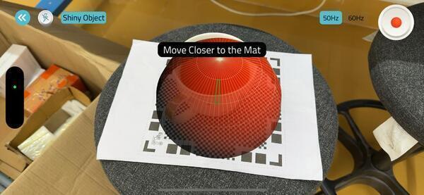
At the right position the dome color changes to blue, thats when we move obeject in circle and let the app capture the images.
It took very less time to capture the 3d model but it didn’y come out right even after several tries.I am assuming thats because of the Tea.
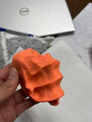
Decided to use scan its clay hand impression because it is small and solid.
3d Printing
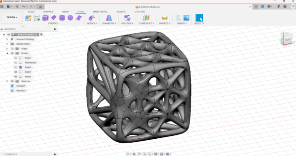
Design Procedure
I made my design in fusion360. I decided to make structure inside a structure by creating a lattice structure using mesh and form bodies for doing this. I refered this tutorial in youtube.
Design 1
-
Started by creating a sphere
-
Next, I did an offset on the body in surface for creating a hollow sphere.
-
Next, I turned off the desing history by right clicking on the document settings because I want to use form bodies later on.
-
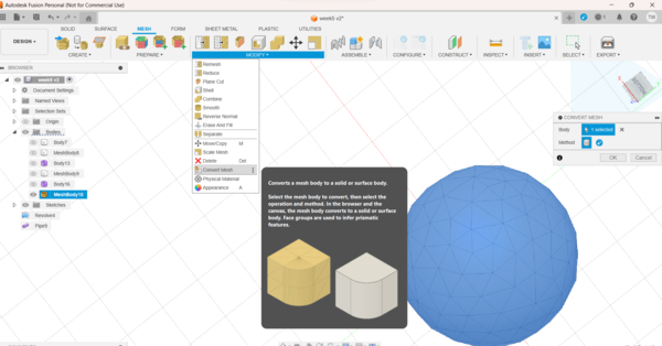
Now, to create a mesh I selected Tessellate, selected the body and played around with the aspect ration and surface deviation.
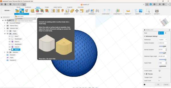
- Did remesh to further refine the mesh
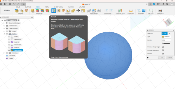
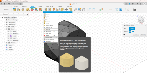
- After getting the desired mesh, Convert the mesh into body.
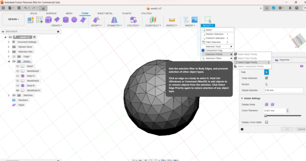
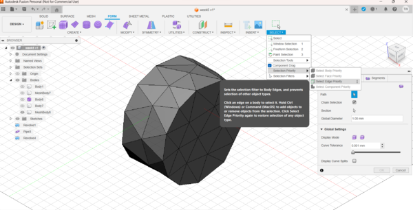
- Now, in the FORM select the create Pipe option and also under select selection priority select Edge priority
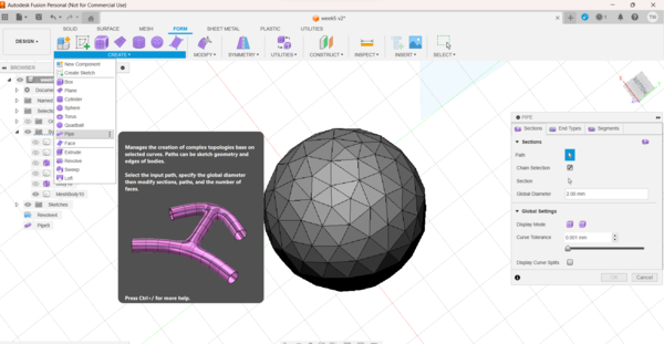
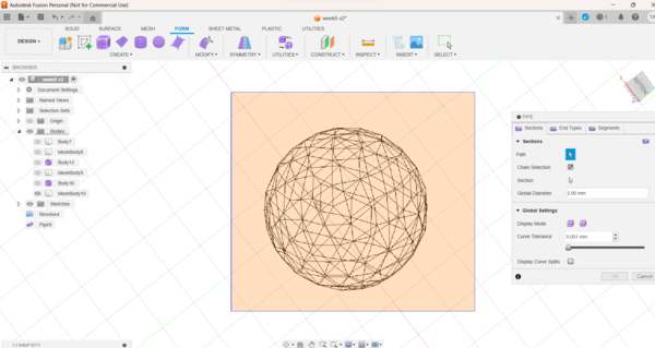
- Select the entire mesh body and then changed the global diameter to 2mm.
Note
Because you cannot capture the desing history, only way to undo you action is by ctrl Z
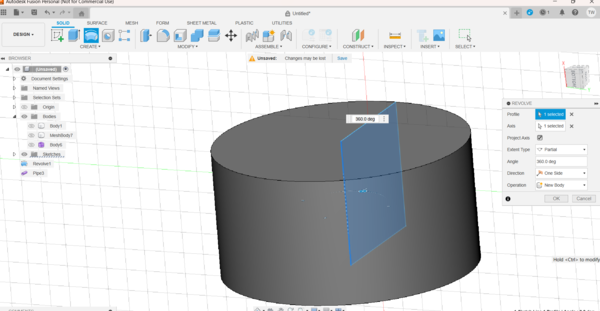
- I also created a cylinder by using the revolve feature and did the offset to create the hollow cylinder.
Same steps were taken to create the mesh and form bodies as done for the sphere as seen below.
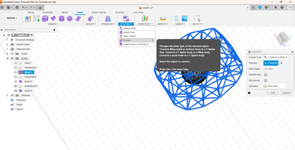
- Finally, after aligining the bodies, convert the Form bodies into “BREP” as shown below.
- Export the Design as a .stl file to be printed.
After importing the design to the Prusa, I splited the object and wanted to rearrange them again.
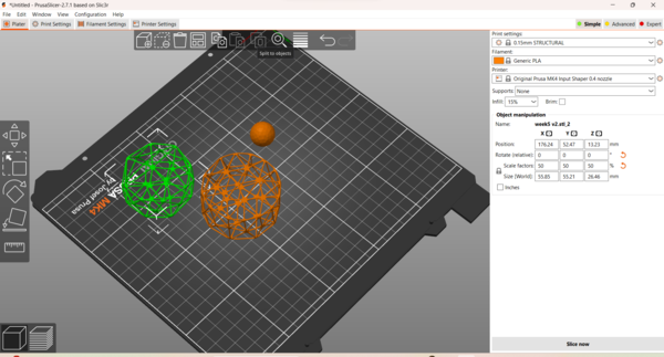
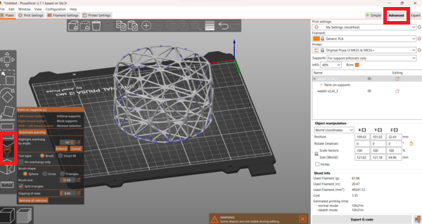
I tried giving the suport everywhere and also tried Advance tool and gave support manually using the paint support tool.
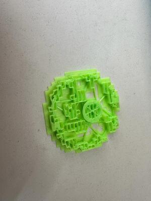
After printing I realised it will be impossible to remove the support without breaking the outer structure as it was too thin.
Failure
Design 2
Made another design using the same process but gave more pipe thickness to make it more study and bulky.
Key Things considered
-
For Mesh design, I was more aware of the angle after the group assignment.
-
Make the pipes more bulky
-
Smaller and uniform
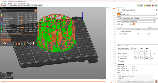
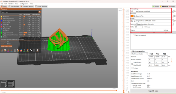
While slicing, it showed very less support and I was happy with it.
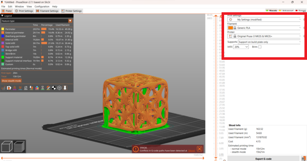
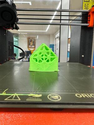
I printed with 20% fill and gave support on build paint only. I kept the the speed to 100% for half way and then increased to 200% after.
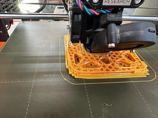
It was not a perfect print as it had stings but it was not too bad. This was the only side with stings as the design there was longer.
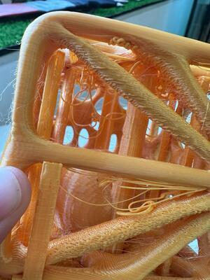
Finally, I took out the support and got my print.
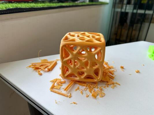
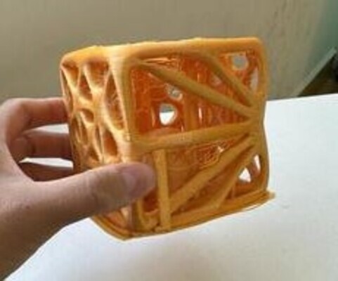
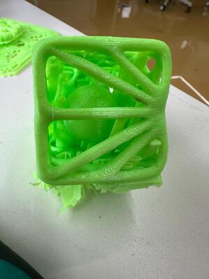
Failure
I intended the ball to be independetly be moving around inside the inclosure but because of support, I was very hard removing the support and there was a chance of breaking the structure. There was also few string on the top of the print.
Final Print
I realized in the above work that my print need few modification to remove the strings and to make the ball mobile.
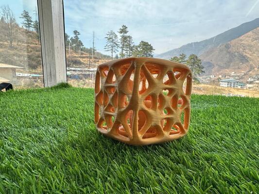
Modified the above design and made it smaller and changed the orientation of the prints as seen below. The reason of printing doing so was because after the group assignment I knew this angle and size wont give any stinging issue. Also adjusted the height of the ball in the center so it wont stick to the base like the previous support.
There is very less support inside and there is no stinging.
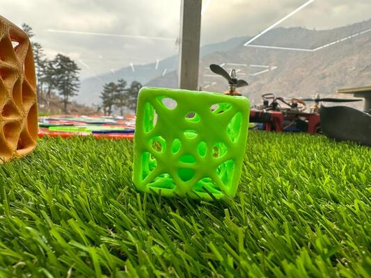
Success!!!
This sturcture could only be made by 3d printing because of the ball is inclosed inside this tight mesh. Using end mills won’t be able to get inside the mill.
Files for the week
I am not able to upload my fusion file as it is too big and even the stl files are too big.