Input Devices
| Task | progress |
|---|---|
| Linked to the group assignment page and document your learning | done |
| Documented your design and fabrication process or linked to the board you made in a previous assignment. | done |
| Explained the programming process(es) you used. | done |
| Included original design files and source code | done |
| Hero Shot | done |
Group Assignment
Here is the link to the group assignment.
Key takeaways from this week:
- You need to get used to using oscilloscope and play around with settings to get the signal. It took us a while to find the signal on oscilloscope.
- While programming sesor was attached to analog pin which is the input pin.
Input Devices
For this week, I wanted try an input device for the final project so I tried with a developement board ESP32 and also did an input device a potentiometer with my own board that I made during electronics design week. Here
PWD with Potentiometer
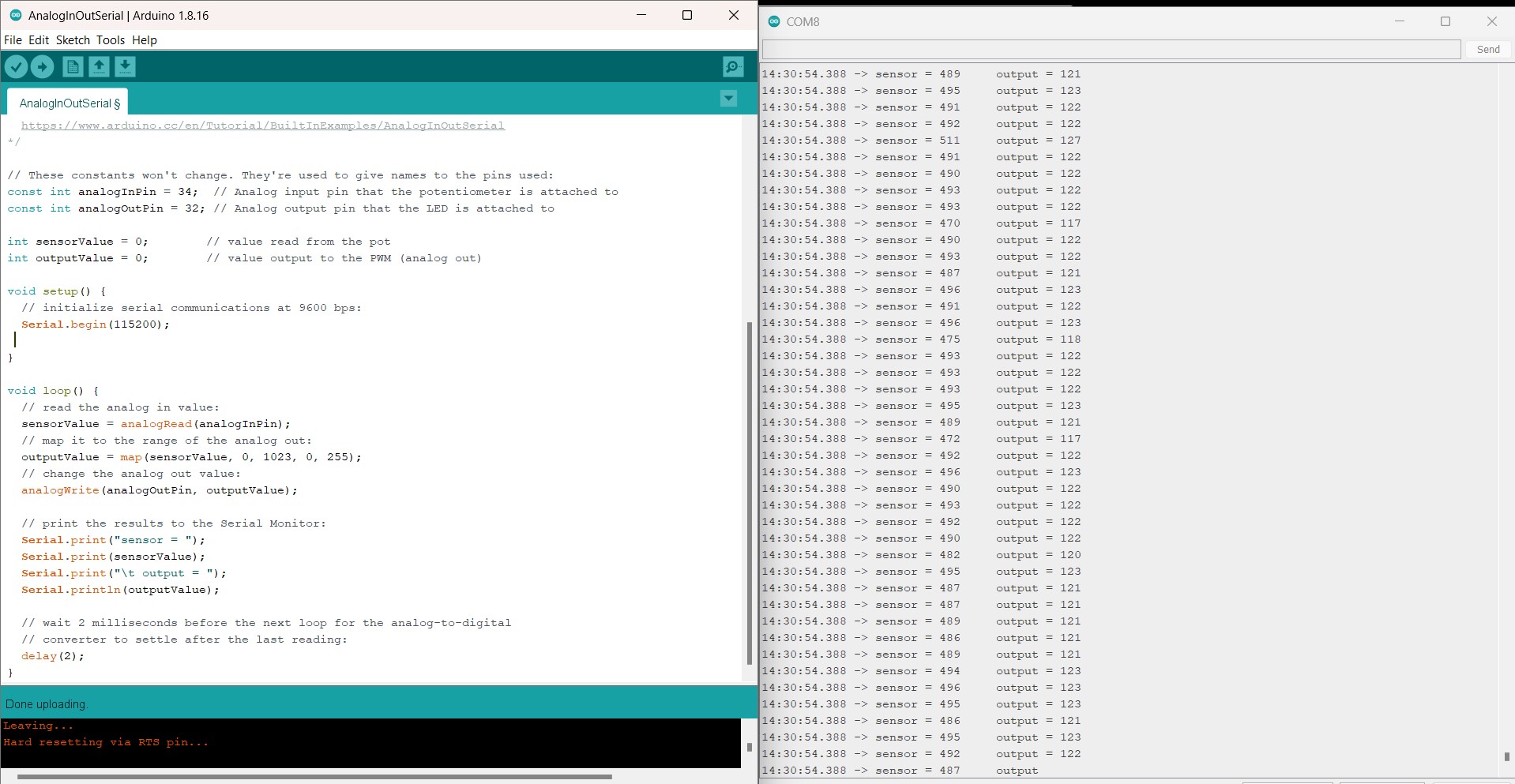
Using Arduino IDE, I went into the example code for AnalogInOutSerial. Using the example code, I changed the analogInPin and analogOutPin to 34 and 32 respectively according to my board design and also made few changes on the existing code. I particularly chose to use pin 34 for input after refering to this pinouts where GPIO34 in written Input only.
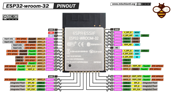 image source: www.mischianti.org
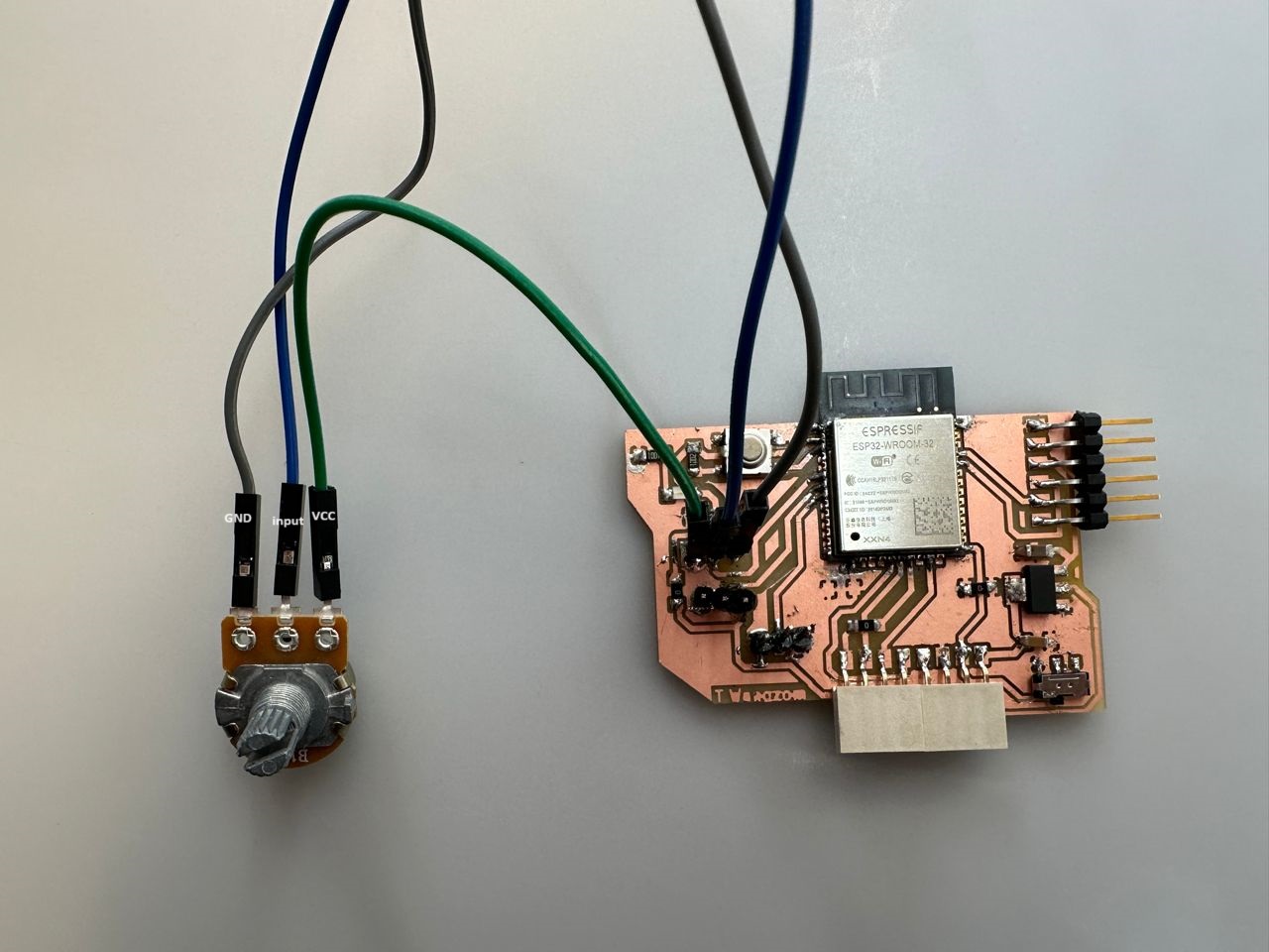
After making the changes to the code, I uploaded to my board which as ESP32 Wroom MCU. Then made the circuit connection with the potentiometer has three leg, GND, Input and VCC pin. I used a 10K potentiometer for this assignment. Shown below is the circuit connection.
HERO SHOT
I opened up the serial Monitor at 115200 baud rate and I was able to observe the output on the serial monitor. The change in potentiometer in pin number 34 from 0-1024 analog signal was mapped to the output signal of 0-255 digital sign.
I connected the output GIPO pin 32 and GND pin to oscilloscope to observe the change in the output signal with change in resistor.
Output can be seen in the video below, where the pulse width changed with change in input signal.
RFID signal
I am using a ESP32 DevModule because in the board that I made, I don’t have all the pinout required for RFID-RC522 module. Here is the connection I made:
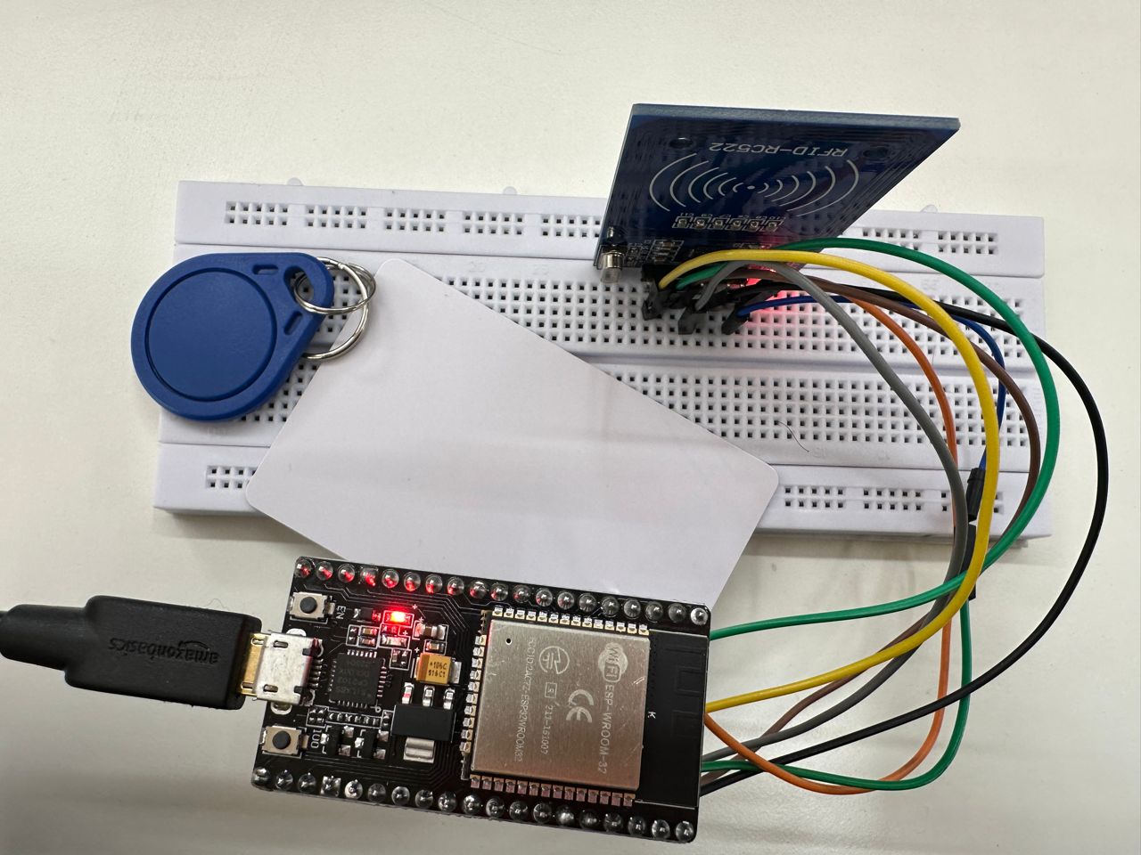
The pin connections are as follows: SDA-22, CLK-19, MOSI-23, MISO-25, GND-GND, RST-22, 3.3V-3.3V
I took reference and guide from few youtube tutorials here
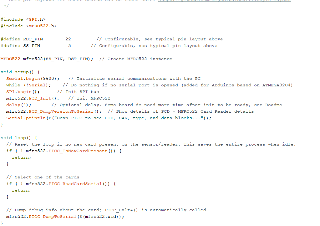
After following the tutorial on this youtube channel, I installed the library for RFID card reader and used the dumpcode in the examples.
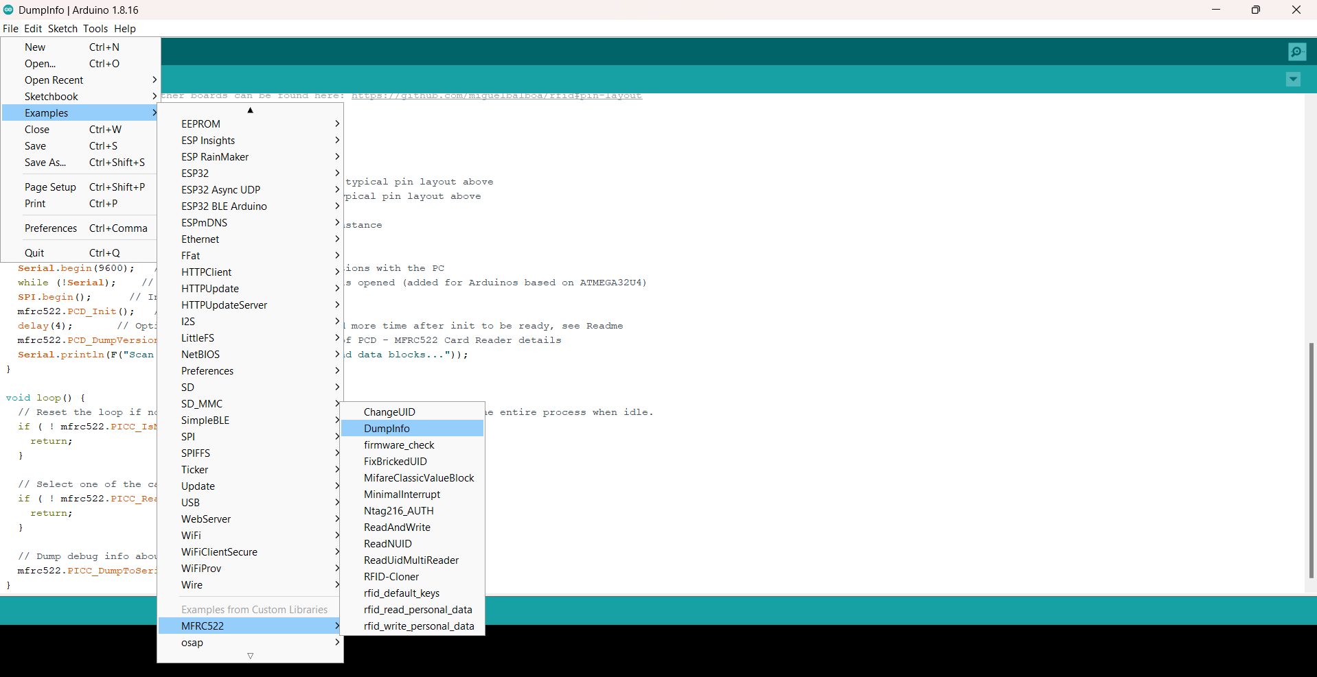
I changed the pin number for RST and CLK.
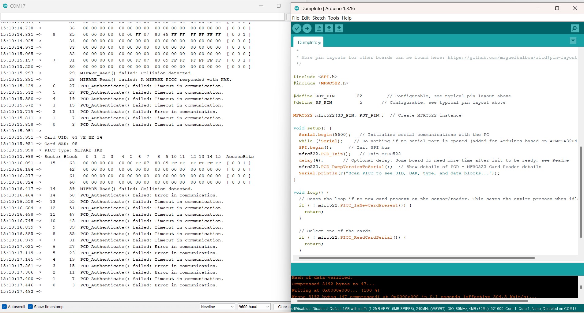
After uploading the code to ESP32 Dev Module, I opened up the serial monitor. AFter this when I placed the RFID card on the reader, the information on the card were being displayed as shown below.
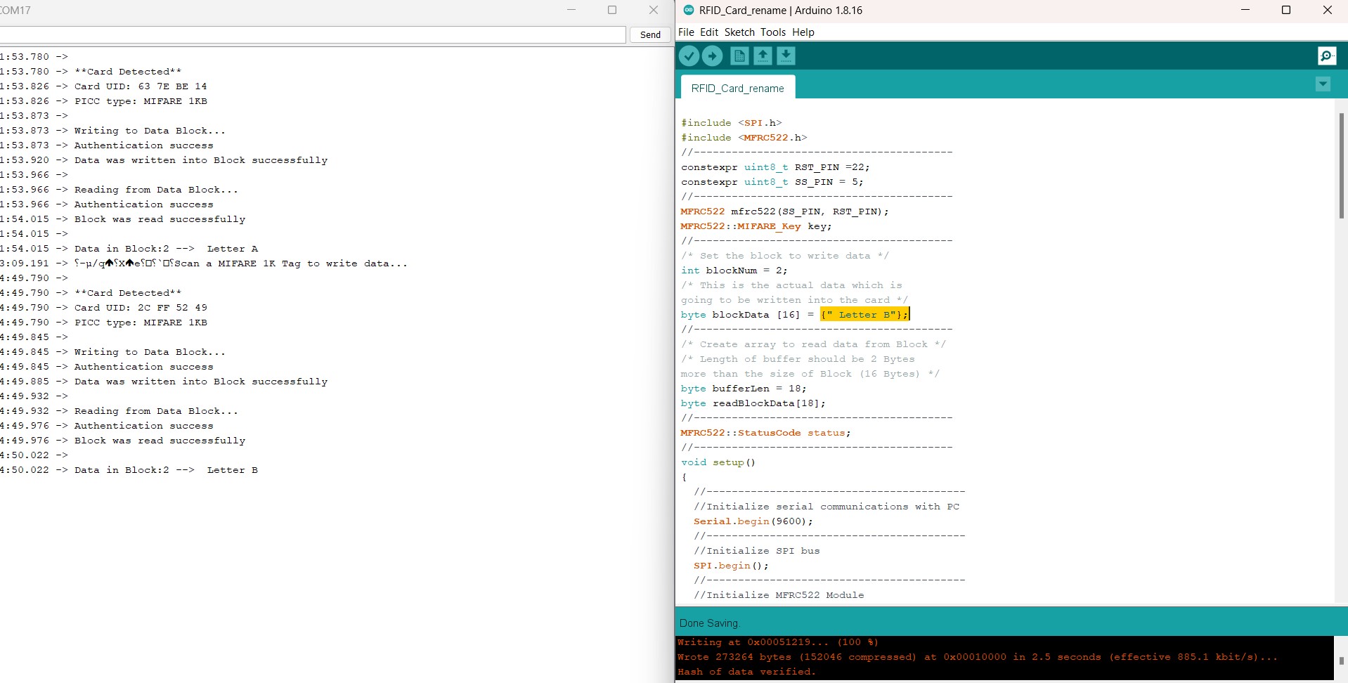
Next, I want to write on the card. So I got this code from here which is tutorial from making automatic locking system.
I changed the data on the block2 of the card. After placing the card on RFID card reader the card information gets updated.