Computer-Controlled Machining
| Task | progress |
|---|---|
| Linked to the group assignment page | done |
| Documented how you designed your object (something big) | done |
| Documented how you made something BIG (setting up the machine, using fixings, testing joints, adjusting feeds and speeds, depth of cut etc.) | done |
| Documented how you made your CAM-toolpath | done |
| Described problems and how you fixed them | done |
| Included your design files and 'hero shot' of your final product | done |
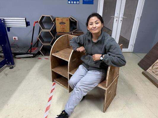
Hero Shot
Group Assignment
Here is the Link to the group Assignment
Key takeaways from this week:
-
PPEs are must, especillly for me it was mask and goggles as I have allergies to dust.
-
It is very important to study your the material thickness before diving into design.
-
It is best to make changes in the dsign then in Vcurve to get the most suitable clearance for joints.
-
While machine operation, always be near the machine,even Shopbot as there can be unforseen accidents.
Designing Shelf/Bench
I started by designing a bench for the lab at first but we had material shorage so I changed my design.
Next, I made a shelf with a bench for kids. I used Fusion360 for making the design.
-
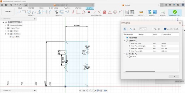
I started by making my sketch for the back of the shelf.
-
I created parameters for slots and the overall dimensions. I made sure to keep the slot height the thickness of the material which is 18mm and length 70mm. I also considered the overall material that was there for this assignment.
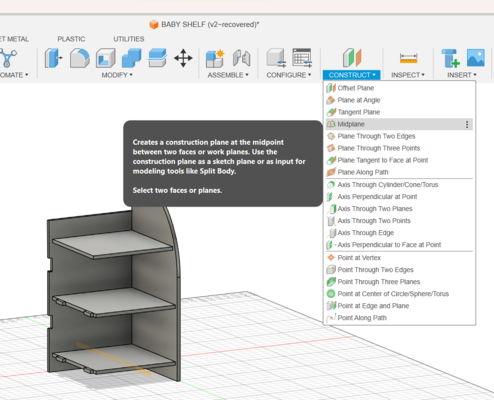
- While replicating slots I created Midplanes and then used mirror under Create. Which was something new this week.
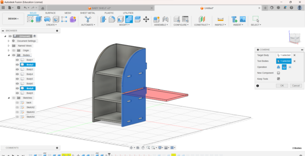
- I also used combine feature under Modify to create Slotgaps. For this We need to select Target and tool bodies.
-
Some of the parts were same so i just replicted them using Move&Copy feature.
-
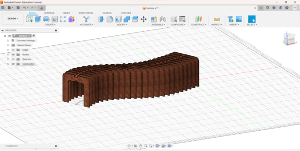
As you can see the entire design was made and assembled in the fusion360. I made a shelf on one side and bench on another side.
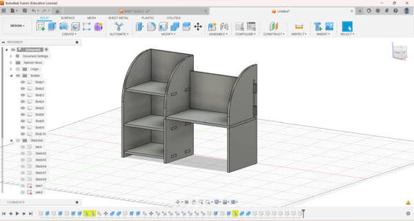
The entire design fits on a 2400mmx1200mm board.
-
I Created new Sketches for individual parts and used project to create new sketches of modified parts.
-
Finally, Save the sketches needed as .dxf files.
VCarve Pro
To generate my CAM tool-path I used VCurve pro. Here are the necessary steps taken to create my tool path.
-
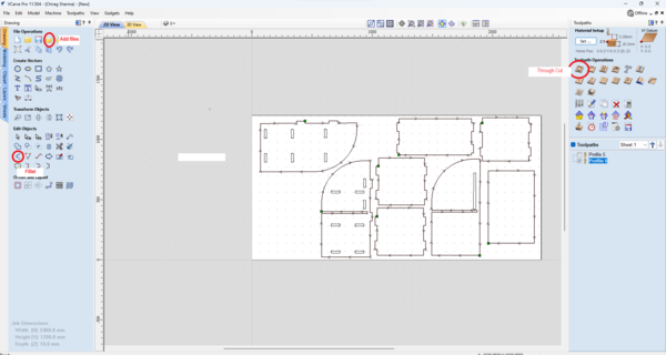
Create a new file and give the dimention/ size of the job peice, in my case was 2400mm x 1200mm.
-
Start opening .dxf files you will be needing by clicking the folder sign shown below.
-
Arrange the drawings as seen fit for maximun usage of the board and as per convience. Use M on key board to move or use keyboard arrows to move the selected drawing.
-
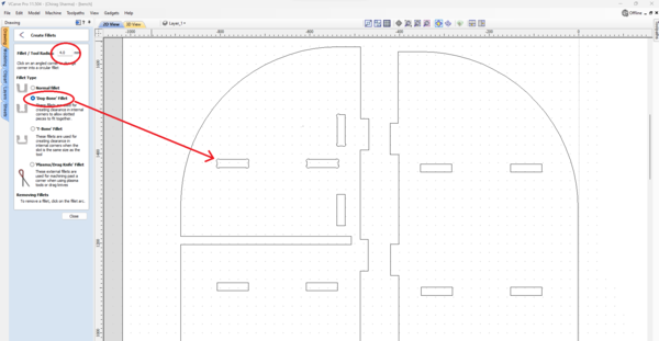
I used VCarve to make my dogbone fillet by clicking on the fillet symbol as shown above.
-
I choose to make 4mm fillet as this worked perfectly for the trial cut.
-
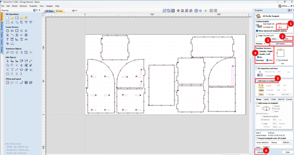
Next was to generate toolpath, which can be done by clicking on the toolpath on the top right hand side. Thing to modify here are:
-
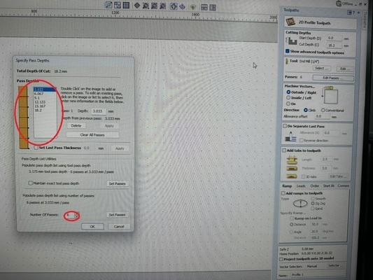
Give the cutting depth the thickness of the material or little more, in my case .2mm more.
-
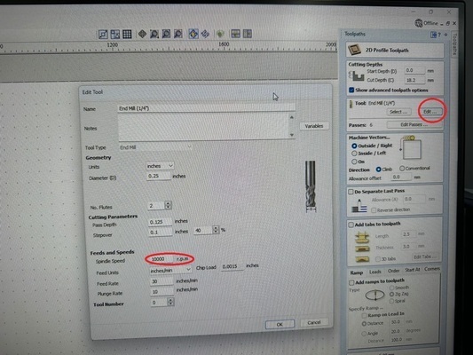
Select End Mill by clicking on edit, I selected 1/4’’ and then also changed the RPM. AS our material was little hard and thicker, we kept the epm at 10000 rpm.
-
We need to select the cutting path of the mill, inside, outside or on the line. *For fillets, select inside and for outer parts use Outside for perfect fit.
-
Press Calculate to generate the path.
-
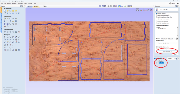
I created two paths, one for the fillets and another one for the outer parts.
-
Save them individually and cut them seperately.
Shopbot
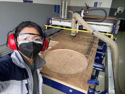
Time to use the our CNC machine, Shopbot.
- Firstly, I geared myself up with all the Personal Protective Equipment
-
Clamped the material on the bed using the clamps.
-
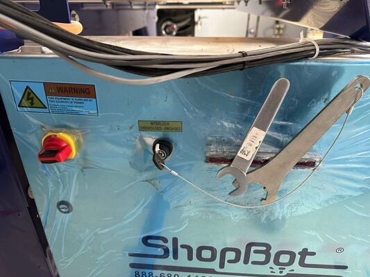
Fixed the end mill using the tools/Wrench for the shopbot which is attached to a key used for engaging the machine.(This is for safty purpose)
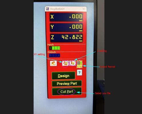
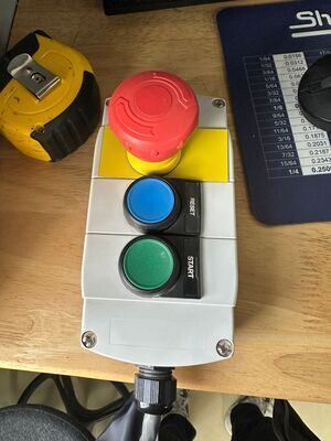
Given below is the control pannel for Shopbot.
- Homing of the endmills X and Y position to the top right corner using the Shopbot control panel on the computer. Click on the zero after selcting X and Y as shown below.
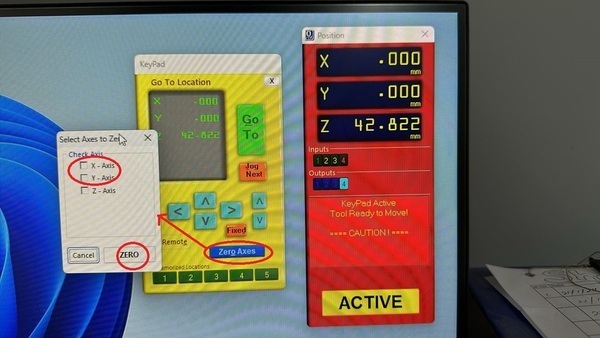
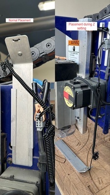
- After setting X and Y, we set Z by using the Probs that are attached to the tool head. Select the Z on the control pannel, it will ask you to place the plate and crocodile clips as shown below. After placing it when we press ok , the z starts moving toward Z and when it touches the plate, it moves back up. This happens twice and the Z axis is set. We place back the probs.
-
The machine is ready for job, we open the tool path we created in VCarve and press OK.
-
A dialouge box will pop up and will ask you to start spinning spindle. Press Start and it will spin the spinddle, only then we press ok on the dialouge box and the machine will start cutting.
Note
Never press OK before starting the spinning spindle, otherwise the endmill will break as it moves towards the job piece without spinning.
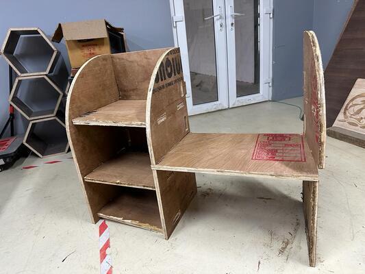
Finally, wait patiently for the machine to do its job while carefully observing for any accidents. Shopbot took more than 3 hours to make my funiture.
It was not a smooth finish as we used ply board which was not of best quality. It was hard to fix them together and it did not come out perfectly because of the clearance and because the material was not consistent with its thickness. But it was usable.
Error and Failures
Error 1
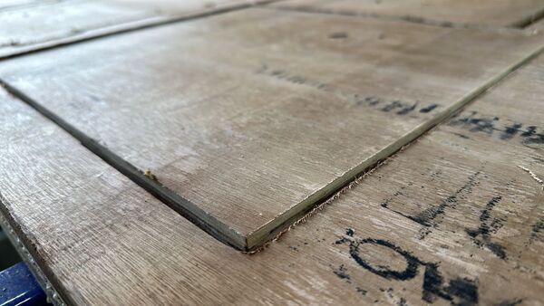
Because we were using old end mill it was not machining the board smoothley as it can be seen below.
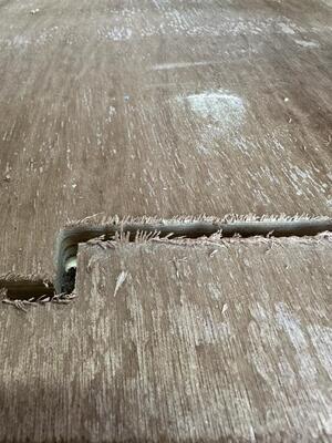
After changing the endmill you can see the difference in the finishing. Unfortunately, I had to use the above board made with old endmill because of the material constrain.
Error 2
I broke two bits, one was purely my fault and another one was because of faulty collet.
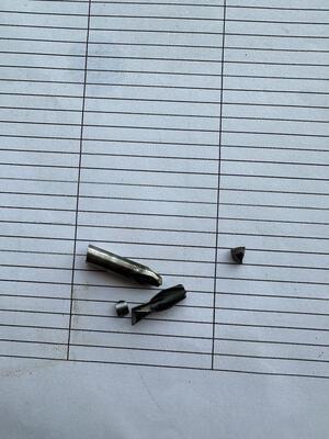
-
I had to press the emergancy stop button because the bit was ploughing thought the material. When I restarted the machine, I forgot to raise the Z and moved the bit because of which I ended up breaking the bit.
-
Because of the faulty collet, as we work though the materail, the end mill droped lower which ended up putting more stress of the end mill and which broke the bit. The ploughing issues was also because of this. We thought it was because we didn’t tighten the collet but that was not the case.