Final project
Wyno key finder
Component
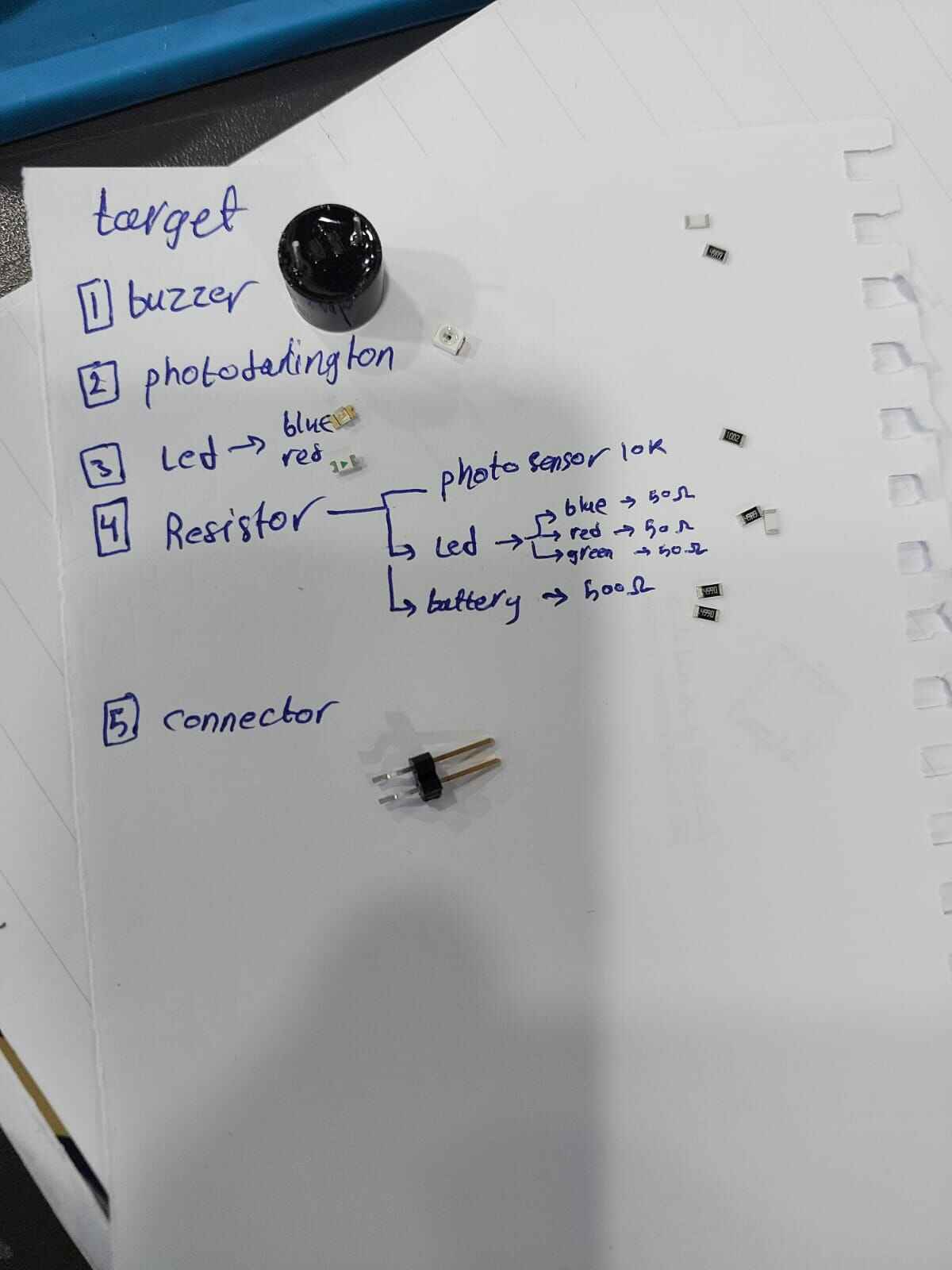
Bill of material
| Item | Description | Quantity | Unit Cost ($) | Supplier |
|---|---|---|---|---|
| Phototransistor | Phototransistor(photo_sensor) | 1 | ~0.50 | Alibaba |
| ESP32C3 | ESP32C3 microcontroller | 1 | ~5.00 | seeedstudio |
| LED | LED (blue and red) | 2 | ~0.50 | Microelectron-Jordan |
| 10k Resistor | Resistor (10k ohm) | 1 | ~0.50 | Microelectron-Jordan |
| material and 3d printing cost | PLA material | 35 gram | each gram cost .3 total will be ~10.5 | Techworks-Jordan lab |
| carton material and laser cutter for packaging | carton material | 1 piece size(60*60 cm) | ~1 | Techworks-Jordan lab |
| vinal cutter sticker | sticker material | 1 piece size(20*20 cm) | ~.5 | Techworks-Jordan lab |
| copper sheet for pcb | A8 Double Side 5*7cm thickness 1.5mm copper sheet | 1 piece | ~1.5 | Microelectron-Jordan |
| Buzzer | Buzzer (specify details if necessary) | 1 | ~0.80 | Microelectron-Jordan |
| Total Cost: | ~20.8 JD (Jordanian dinar) | |||
circuit design and fabrication
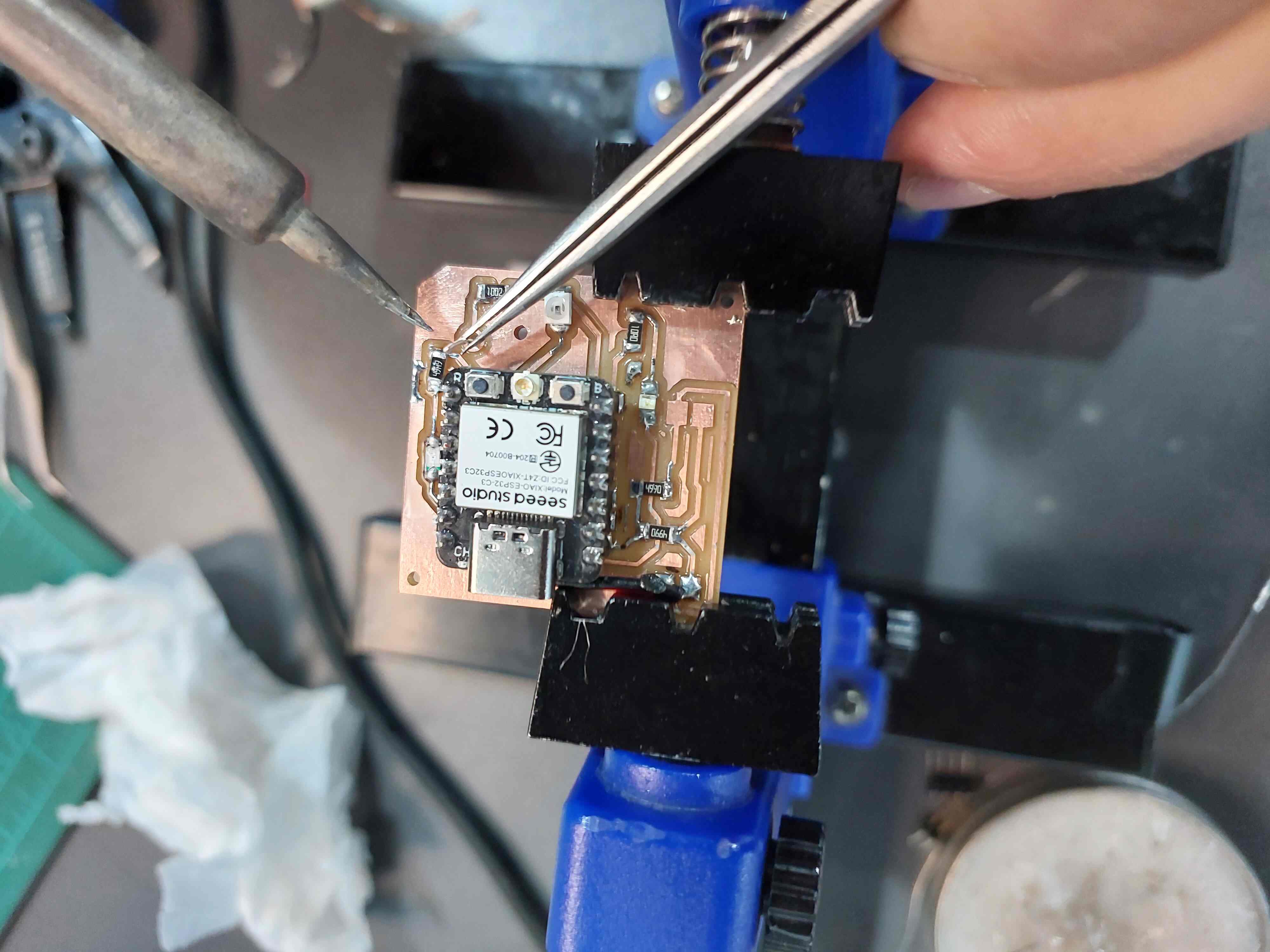
For the circuit design of my final project, I utilized Eagle software. The design incorporates components on both sides of the board, requiring through-hole connections. The buzzer will be positioned on the bottom layer, while the MCU (microcontroller unit) and photo sensor will be on the top layer. To accomplish this design, I drew upon my experience from Electronic Production week, where I previously worked on a double-sided board.
After completing the board design, I proceeded to fabricate the circuit. I followed the necessary steps, including cutting the board according to the design specifications. Once the board was prepared, I initiated the soldering process to connect the components and ensure proper functionality.


programming and Ble comunication
In the programming aspect of my final project, I incorporated my knowledge and experiences from the Networking & Communications and Interface & Application Programming weeks. During the Networking and Communications week, I learned how to program two devices to establish a connection using Bluetooth Low Energy (BLE). Additionally, during the Application Programming week, I acquired skills in developing applications and connecting them with other devices through BLE for control purposes.
For my final project, I aimed to incorporate an additional feature alongside the communication aspect. This feature involved utilizing the functionality of the photosensor. To implement this, I added a section of code, clearly commented, which defines a threshold value. This threshold value is compared with the difference between the current value and the previous value of the photosensor. If the difference exceeds the threshold value, the buzzer will emit a single beep, and this action will continue based on subsequent comparisons.
By integrating BLE communication, leveraging my previous programming knowledge, and introducing the photosensor functionality, I successfully implemented a comprehensive and functional programming aspect in my final project.

I explain the code in detail in Interface & Application Programmingweek

The Target device code (I mean wyno medal device)
            #include
            #include
            #include
            #include

            #define led_pin 21
            #define led_pin2 20
            #define piezo 4
            #define photoPin 3
            uint32_t counterpointer=3;

            // Variable to store the previous light value
            int prevLightValue = 0;

            // Define the threshold for significant light value change
            int threshold = 800; // Adjust as needed

            // Define the range limits for triggering the buzzer
            int lowerThreshold = 100; // Adjust as needed
            int upperThreshold = 900; // Adjust as needed

            BLEServer* pServer = NULL;
            BLECharacteristic* pCharacteristic = NULL;
            BLECharacteristic* pCharacteristic_2 = NULL;
            BLEDescriptor *pDescr;
            BLE2902 *pBLE2902;

            bool deviceConnected = false;
            bool oldDeviceConnected = false;
            uint32_t value = 0;

            // See the following for generating UUIDs:
            // https://www.uuidgenerator.net/

            #define SERVICE_UUID        "4fafc201-1fb5-459e-8fcc-c5c9c331914b"
            #define CHAR1_UUID          "beb5483e-36e1-4688-b7f5-ea07361b26a8"
            #define CHAR2_UUID          "e3223119-9445-4e96-a4a1-85358c4046a2"

            class MyServerCallbacks: public BLEServerCallbacks {
                void onConnect(BLEServer* pServer) {
                  deviceConnected = true;
                };

                void onDisconnect(BLEServer* pServer) {
                  deviceConnected = false;
                }
            };

            class CharacteristicCallBack: public BLECharacteristicCallbacks {
              void onWrite(BLECharacteristic *pChar) override {
                std::string pChar2_value_stdstr = pChar->getValue();
                String pChar2_value_string = String(pChar2_value_stdstr.c_str());
                int pChar2_value_int = pChar2_value_string.toInt();
                counterpointer=pChar2_value_int;
                Serial.println("pChar2: " + String(pChar2_value_int));
              }
            };

            void setup() {
              Serial.begin(115200);
              pinMode(led_pin,OUTPUT);
              pinMode(led_pin2,OUTPUT);

              // Create the BLE Device
              BLEDevice::init("ESP32");

              // Create the BLE Server
              pServer = BLEDevice::createServer();
              pServer->setCallbacks(new MyServerCallbacks());

              // Create the BLE Service
              BLEService *pService = pServer->createService(SERVICE_UUID);

              // Create a BLE Characteristic
              pCharacteristic = pService->createCharacteristic(
                                  CHAR1_UUID,
                                  BLECharacteristic::PROPERTY_NOTIFY
                                );

              pCharacteristic_2 = pService->createCharacteristic(
                                  CHAR2_UUID,
                                  BLECharacteristic::PROPERTY_READ   |
                                  BLECharacteristic::PROPERTY_WRITE
                                );

              // Create a BLE Descriptor

              pDescr = new BLEDescriptor((uint16_t)0x2901);
              pDescr->setValue("A very interesting variable");
              pCharacteristic->addDescriptor(pDescr);

              pBLE2902 = new BLE2902();
              pBLE2902->setNotifications(true);

              // Add all Descriptors here
              pCharacteristic->addDescriptor(pBLE2902);
              pCharacteristic_2->addDescriptor(new BLE2902());

              // After defining the desriptors, set the callback functions
              pCharacteristic_2->setCallbacks(new CharacteristicCallBack());

              // Start the service
              pService->start();

              // Start advertising
              BLEAdvertising *pAdvertising = BLEDevice::getAdvertising();
              pAdvertising->addServiceUUID(SERVICE_UUID);
              pAdvertising->setScanResponse(false);
              pAdvertising->setMinPreferred(0x0);  // set value to 0x00 to not advertise this parameter
              BLEDevice::startAdvertising();
              Serial.println("Waiting a client connection to notify...");
            }

            void loop() {
                // notify changed value
                digitalWrite(led_pin2,LOW);
                digitalWrite(led_pin,LOW);
                int currentLightValue = analogRead(photoPin);
                // Check if the light level is outside the specified range
                  if (abs(currentLightValue - prevLightValue) > threshold) {
                  // Trigger the piezo buzzer to ring once
                  digitalWrite(led_pin, HIGH);
                  tone(piezo, 1000); // Adjust the frequency and duration as needed
                  delay(500); // Delay to avoid multiple triggers for the same change
                  digitalWrite(led_pin2, LOW);
                  // Turn off the piezo buzzer
                  noTone(piezo);
                  delay(500); // Delay to avoid multiple triggers for the same change

                  // Update the previous light value
                  prevLightValue = currentLightValue;

                  // Print the current light level to the serial monitor
                }
                if (deviceConnected) {
                    pCharacteristic->setValue(value);
                    pCharacteristic->notify();
                    value++;
                    delay(1000);

                    if (counterpointer==1){
                    digitalWrite(led_pin,OUTPUT);
                    Serial.println("helooooooooooooooo");
                    Serial.println(digitalRead(led_pin));
                    digitalWrite(led_pin,HIGH);
                    digitalWrite(led_pin2,LOW);

                    tone(piezo, 1000); // Send 1KHz sound signal...
                    delay(500);        // ...for 1 sec
                    digitalWrite(led_pin,LOW);
                    digitalWrite(led_pin2,HIGH);
                    noTone(piezo);     // Stop sound...
                    delay(500);        // ...for 1sec
                }else{
                  digitalWrite(led_pin,LOW);
                  digitalWrite(led_pin2,LOW);
                }

                }
                // disconnecting
                if (!deviceConnected && oldDeviceConnected) {
                    delay(500); // give the bluetooth stack the chance to get things ready
                    pServer->startAdvertising(); // restart advertising
                    Serial.println("start advertising");
                    oldDeviceConnected = deviceConnected;
                }
                // connecting
                if (deviceConnected && !oldDeviceConnected) {
                    // do stuff here on connecting
                    oldDeviceConnected = deviceConnected;
                }
            }
3D design and Manufacturing
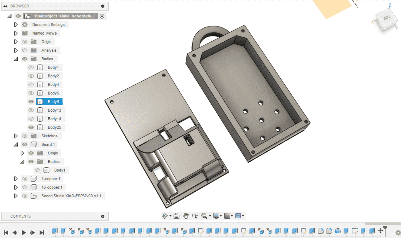
For the 3D design and fabrication phase of my final project, I utilized Fusion 360 software to create an enclosure design. The design consists of two pieces: one to cover the top layer and another to hold the battery and cover the bottom layer. I focused on achieving a smooth and visually appealing design that would cover all the circuit components. I incorporated specific holes in the design to accommodate the LED, photo sensor, and C-type port. Additionally, I included holes at the edges of both pieces to allow for easy assembly using screws.
To fabricate the enclosure, I use the Ultimaker S6 printer and PLA (polylactic acid) as the printing material. However, I encountered several challenges during the printing process. Initially, the first layer of the print did not adhere properly to the build plate, indicating an issue with bed leveling. To address this, I adjusted the bed leveling and applied a thin layer of glue to enhance adhesion. Furthermore, I reduced the printer speed for the initial layers to mitigate the problem. Although I faced minor issues such as nozzle material blockage, regular cleaning resolved them. Despite these challenges, the overall outcome of the printing process was satisfactory, and I achieved a high-quality result.
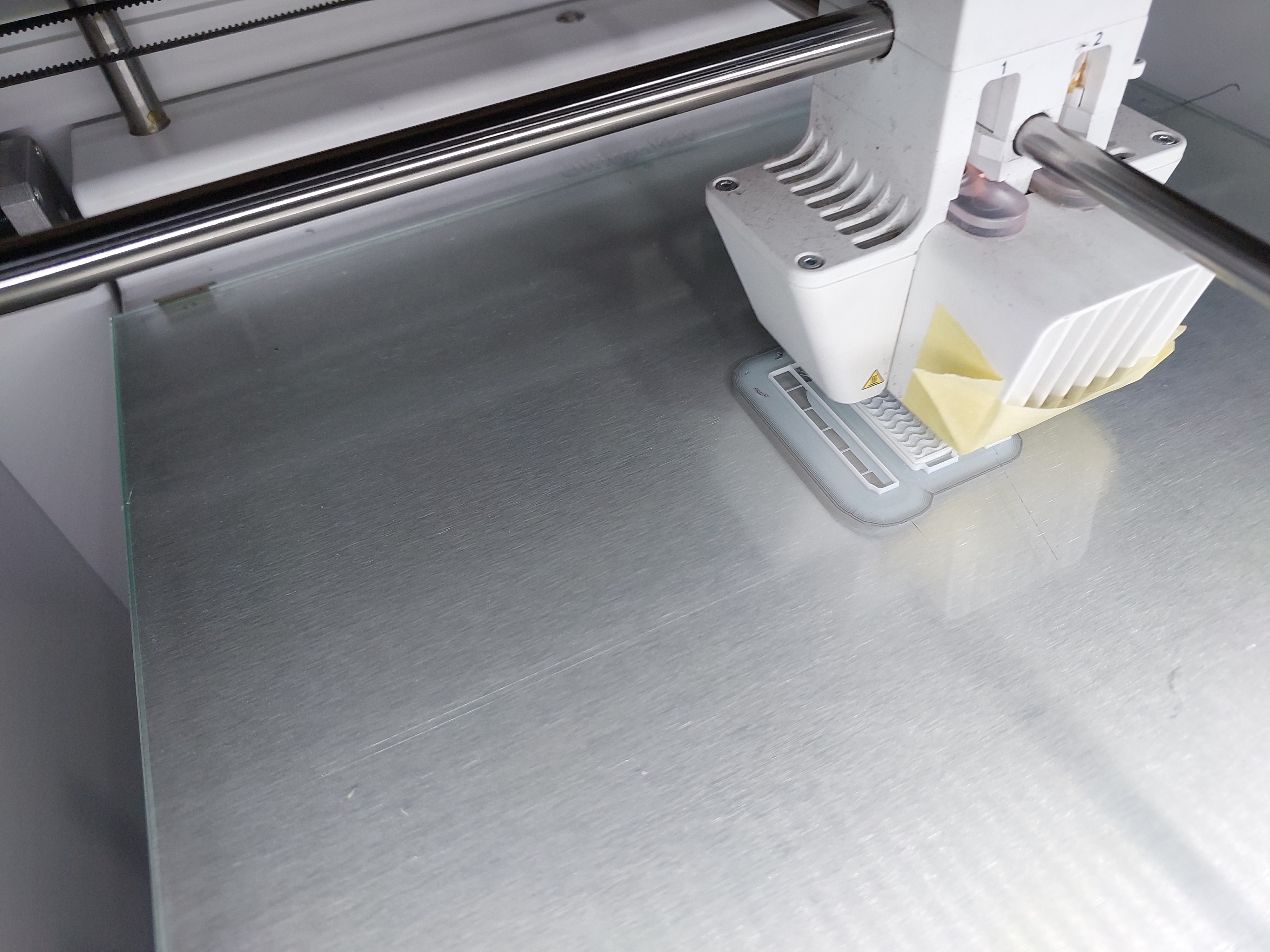
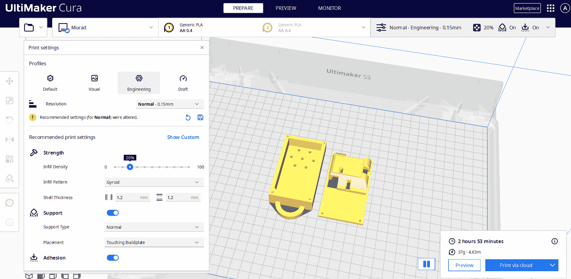
During the Cura slicing process, I made specific adjustments to optimize the print quality and support structure of my project's enclosure. Key settings included a 20% infill percentage for structural support and the gyroid filling pattern for the support structure. I also set the support placement to "Touching Build Plate" to minimize the need for additional support removal and improve overall print quality. Other settings were left at their default values, ensuring efficient and satisfactory results. The combination of these settings allowed for a successful print outcome
packaging and logo
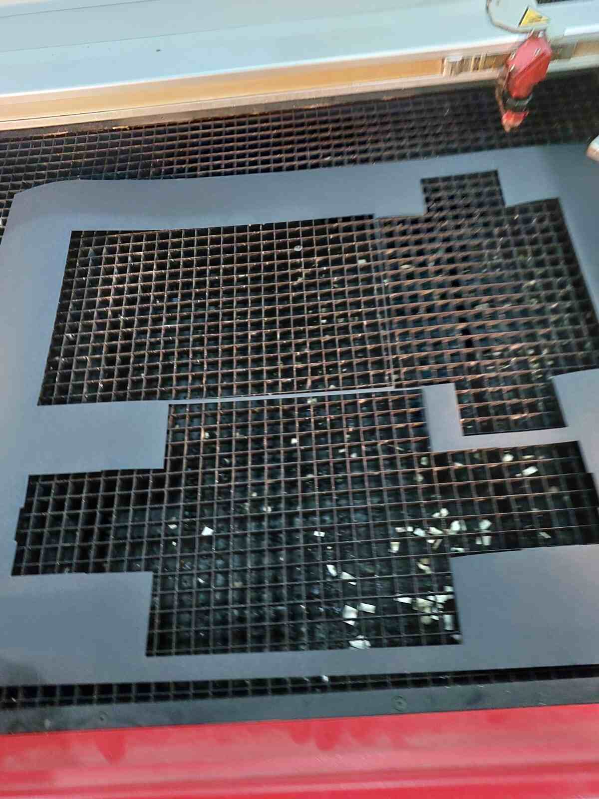
To create the packaging for my final project, I utilized AutoCAD software to design a 2D sliding box with a cover. Once the design was complete, I proceeded to cut the design onto a carton sheet using a laser cutter. The laser cutter settings were adjusted with a cutting power of 100 and a speed of 10. Additionally, I utilized the marking function with a power of 70 and a speed of 40 to create visible lines that aided in identifying where the carton should be folded. After cutting the design, I assembled the packaging.
For the logo on the packaging, I used Inkscape software to create the design. Once the logo design was finalized, I exported it as a PNG file. To apply the logo onto the packaging, I utilized a Roland vinyl cutter. The PNG file was used with the vinyl cutter to precisely cut and create the logo on a suitable vinyl material.
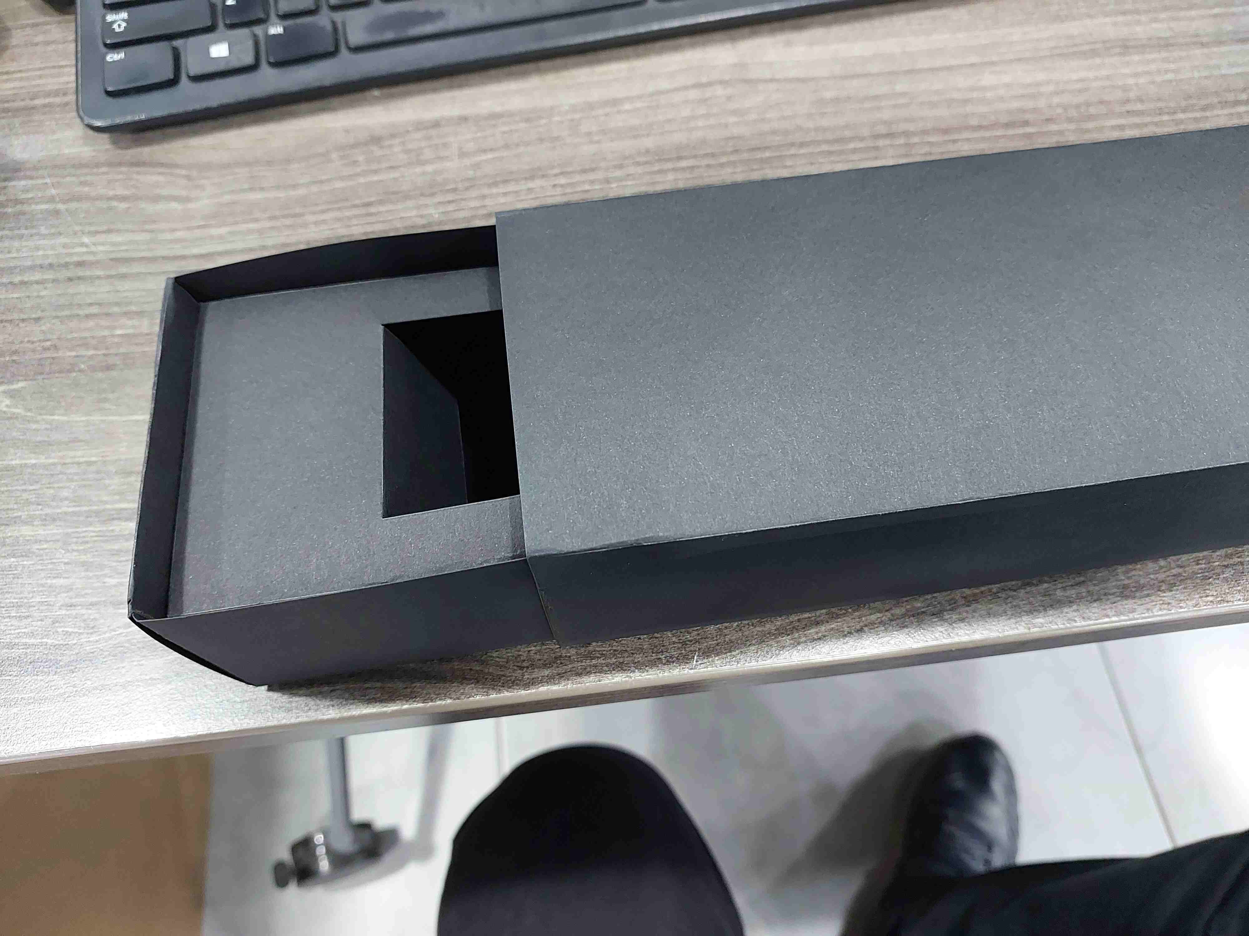
for logo I used Roland vinal cutter ,to make sticker I follow the steps I did in computer_controlled cutting week
.jpg)
.jpg)
License Selection for My Project
I have decided to choose the Apache License 2.0 for my project. This open-source license allows users to freely use, modify, and distribute the software, both for commercial and non-commercial purposes. It also includes patent and trademark grants, providing additional legal protections.
I believe that selecting the Apache License 2.0 will help foster a vibrant community around my project. It encourages collaboration and contribution, allowing others to add features, make improvements, and share their modifications with the community. This license promotes an open and inclusive environment, empowering developers to build upon and benefit from the work I have done.
By choosing the Apache License 2.0, I aim to support the growth and development of the open-source community, enabling others to freely use and enhance my project for their own purposes.
License for the documentation and final project
The content and source files of this project are licensed under the Apache License 2.0.
This means that you are free to use, modify, and distribute both the documentation and the source files, for both commercial and non-commercial purposes, under the terms of the Apache License 2.0.

Inspiration
The idea came to me while I was on a weekend and needed to use my car. I struggled to find my car key and searched everywhere in my home, which took a lot of time. After giving up on finding the key, I put my hand in my pocket and found that I had put it there. That's when I thought of creating a device that would produce a sound and be connected to my key, so I wouldn't have to go through the hassle of searching for it again.
Idea Specification
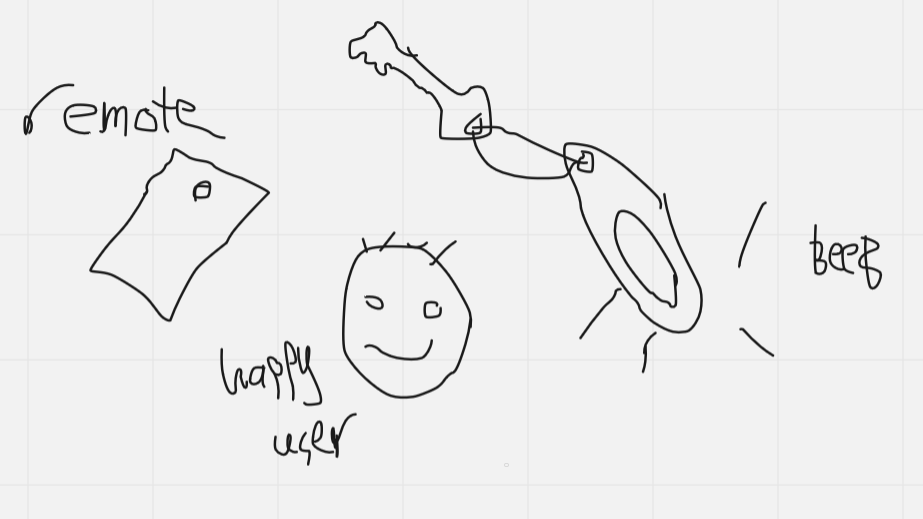
- The idea is to create a system consisting of two components: a remote that can be worn and a device that can be attached to a key.
- The remote will be used to send a signal to the device attached to the key to make a sound.
- The system will use Bluetooth Low Energy (BLE) to establish a connection between the two components.
- The purpose of the system is to help users quickly locate their keys when they are lost.
Application and Implication
What will it do?
The key finder medal will help people locate their keys. It consists of a remote and a target. When the user presses a button on the remote, it sends a signal to the target. The target, when activated, emits a beeping sound and activates a light, making it easier to find the keys.
Who's done what beforehand?
Similar products, such as iTags and other key finders, already exist in the market. These products utilize Bluetooth technology to establish a connection between a remote and a target to locate lost items.
What will you design?
You will design a key finder medal that includes a remote and a target. The remote will have a push button and an XIO ESP32C microcontroller. The remote will also be redesigned to be wearable on the hand for convenient usage. The target will have a buzzer, a light, a light sensor, and an XIO ESP32C microcontroller.
What materials and components will be used?
Materials:
- PCB board for remote (made with PCB fabrication using a PCB design software)
- Flexible and smooth TPU material for the target
- PLA material for the redesigned wearable remote
Components:
- XIO ESP32C microcontroller for both remote and target
- Push button for the remote
- Buzzer for the target
- Light module for the target
- Light sensor for the target
- Bluetooth Low Energy (BLE) module for communication
- Passive components (resistors, capacitors, etc.) for circuitry
- Rechargeable lithium battery (3.7V) for power
- Switch for on/off functionality on the remote
Where will they come from?
The materials and components can be sourced from electronic component suppliers, online retailers, or local electronics stores.
How much will they cost?
The cost of the materials and components will vary depending on the specific brands, quantities, and suppliers chosen. It is recommended to research and gather price estimates from different sources to determine the overall cost.
What parts and systems will be made?
The parts that will be made include:
- PCB board for the remote, which will be designed using PCB design software and manufactured using PCB fabrication methods.
What processes will be used?
The processes involved in the project may include:
- Designing the remote and target using CAD software
- Designing the PCB layout using PCB design software
- PCB fabrication for the remote
- Soldering and assembly of electronic components onto the PCB
- Programming the microcontrollers for both remote and target
- Testing and troubleshooting the functionality of the key finder system
What questions need to be answered?
Some questions that need to be answered during the project may include:
- How to optimize power consumption for extended battery life?
- How to ensure reliable and secure communication between the remote and target?
- How to design an intuitive user interface for the remote?
- How to calibrate the light sensor for accurate detection?
- How to optimize sound come from target inclosure ?
How will it be evaluated?
The key finder medal can be evaluated based on its effectiveness in locating keys, the reliability of the Bluetooth communication, the responsiveness of the remote button, the convenience and wearability of the redesigned remote, and the overall user experience. User feedback and testing can be used to assess the performance and usability of the key finder medal.
| Component | Remote | Target |
|---|---|---|
| Microcontroller | XIO ESP32C | XIO ESP32C |
| Material | PLA | TPU |
| Button | Push Button | --- |
| Buzzer | --- | Buzzer |
| Light | --- | Light Module |
| Light Sensor | --- | Light Sensor |
| power | Li battery 3.7 V | Li battery 3.7 V |
| Functionality | Send Bluetooth signal to activate the target | Emit beeping sound and activate light when triggered |
| specification & Modification | Make it wearable on hand,make its enclosure easy to open for maintenance purpose | work on attachment method, Investigate different materials for enhanced durability or flexibility |
.svg)

