12. Molding and Casting
This week I worked on molding and casting. It was my first experience with this technique. During the group work, we looked at safety instructions.
Building Stock
I decided to build a chess piece (King) for this week. The 3D model was created in OpenSCAD. I made a mistake which I realized only after milling (when I met my local instructor). I should have created a positive model, but I made a negative model before the milling. However, it has a roughing cut and a three-axis finishing cut as required in the assignment.
I used the OpenSCAD code for Chess King from here, but I had to modify it to make a stock for the mold.
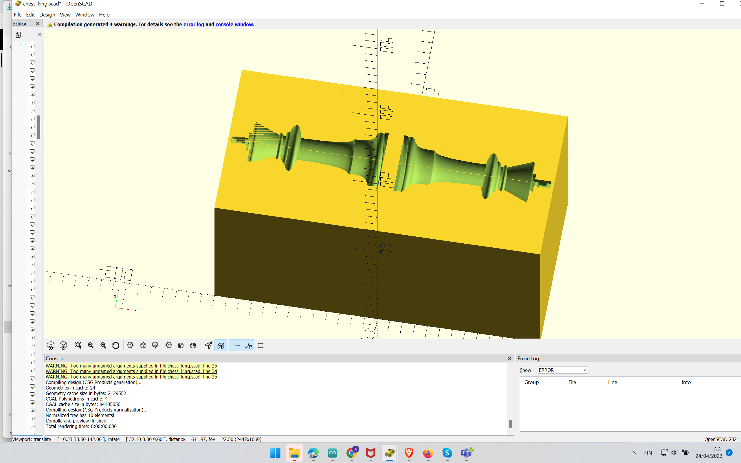 Figure 0: Making Chess Negative Mold in OpenScad
OpenScad program can be found here.
The STL file can be found here.
Milling
First I needed to create a toolchain profile for rough cut and finish cut. The milling bit was 3.18 mm in diameter.
Figures 1 to 12 (mentioned in sequential order) show steps to create a Rough cut toolchain.
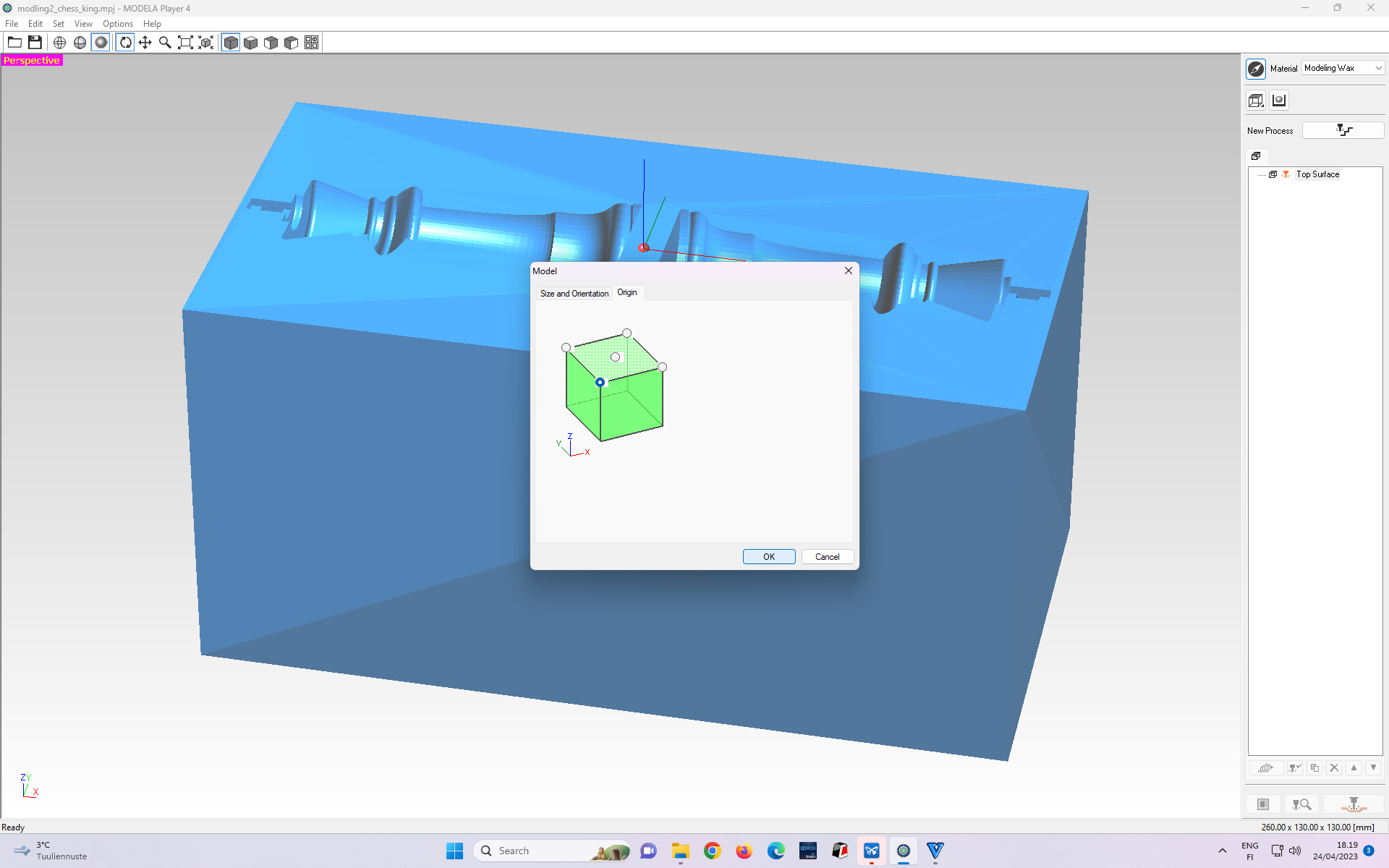 Figure 1: Software Interface after importing the STL file
Figures 2 and 3 show the steps of choosing “roughing cut.”
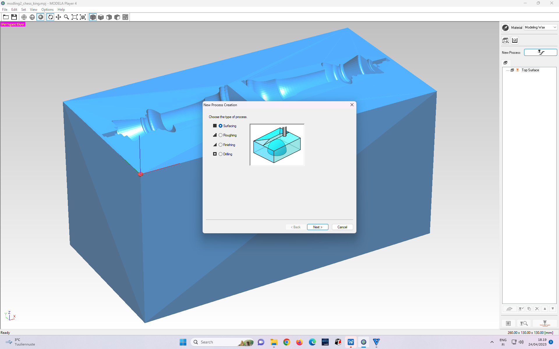 Figure 2: Next, we choose the “Roughing” Cut. Right now default selection is “Surfacing” cut.
 Figure 3. Selecting the “Roughing” Cut option.
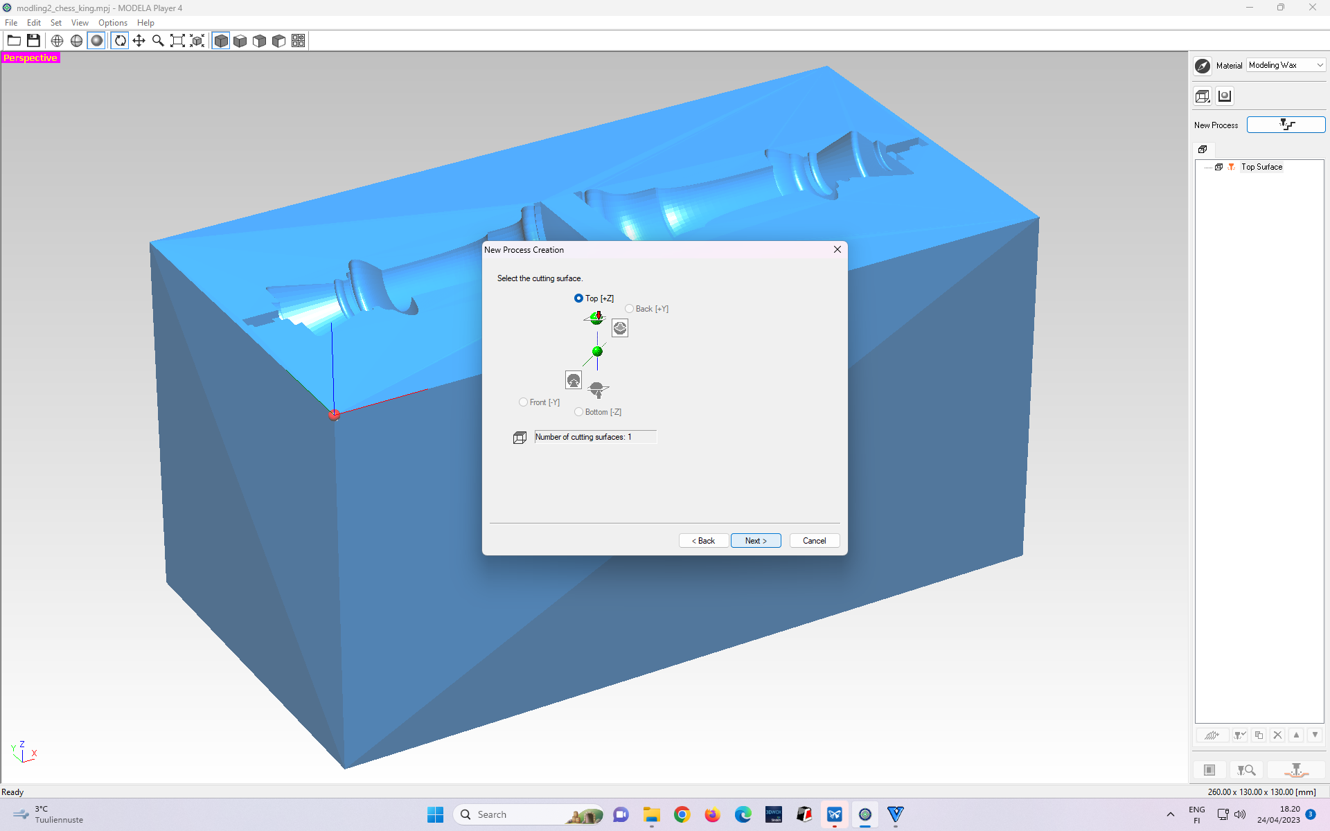 Figure 4. It sets the initial axis. We select top[+Z] since milling will be from the direction of the Z-axis. Then, Press Next.
 Figure 5. Next, we need to select the tool with the right diameter matching our tool (blade). I chose 3.18 mm since our tool(blade) had this diameter.
In Figures 6 and 7, select the partial zone to be milled, since I only want the region within which my stock is to be milled.
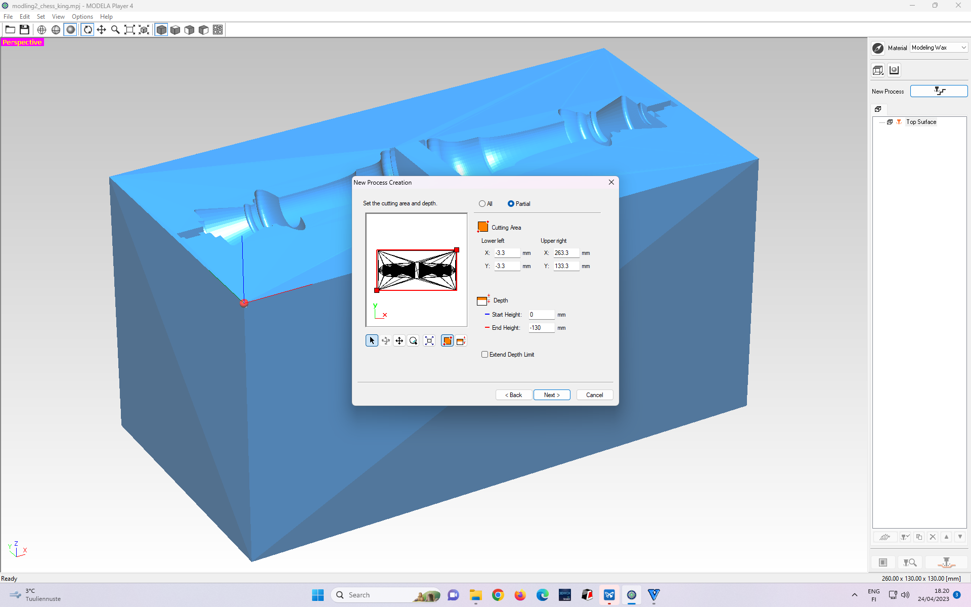 Figure 6: By default, even the area beyond the stock region is within milling coverage.
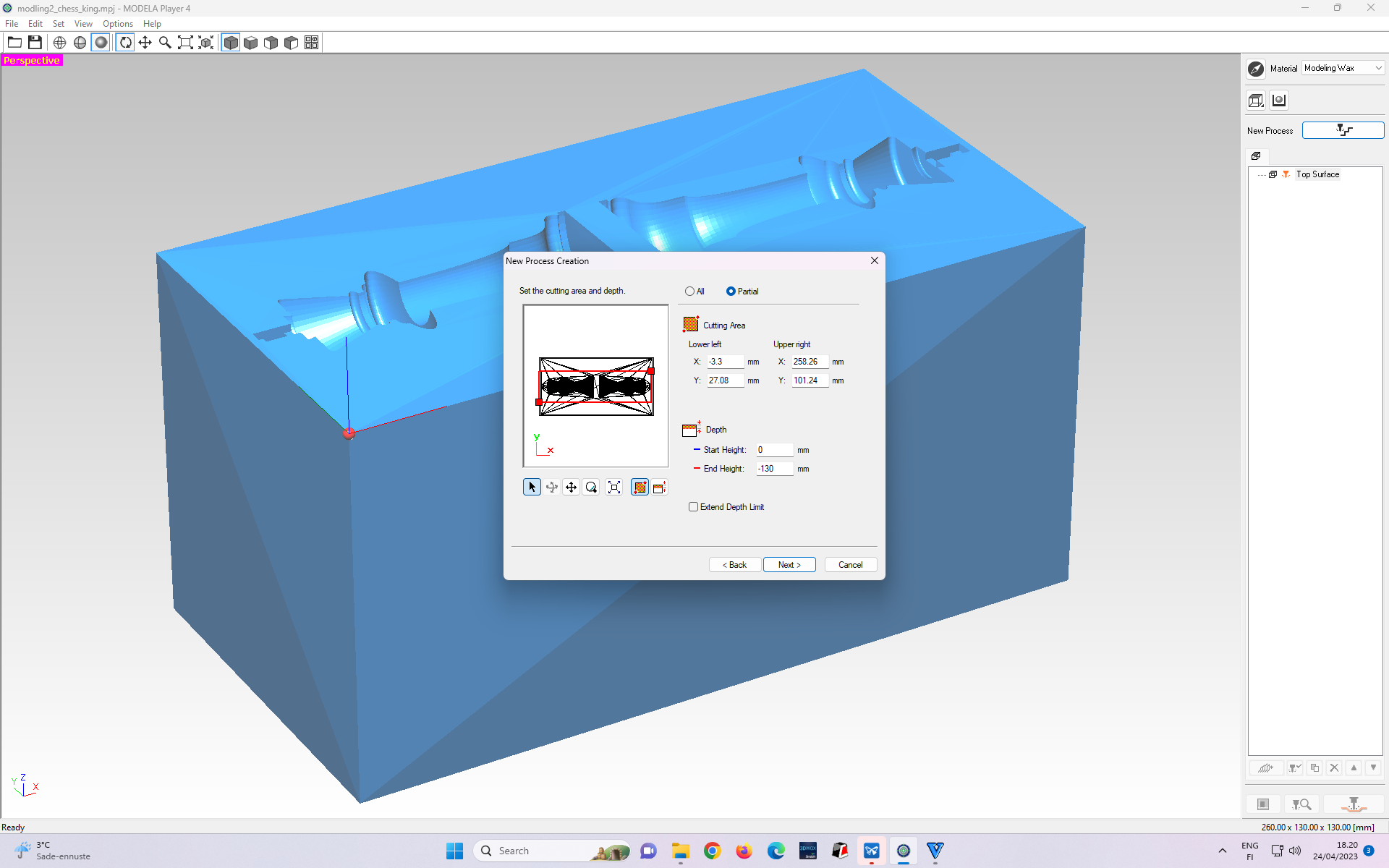 Figure 7: I adjust the area such that milling will be done in the stock region only.
 Figure 8. Here, I select the “Contour Lines” tab and “Up Cut” within this tab. Then, press Next.
 Figure 9. The Dialogue box shows the summary of cutting parameters. If all parameters seem appropriate, we select Next, otherwise, we select “Back” to return to the previous step to modify the relevant cutting parameters.
 Figure 10: Renaming the Roughing cut process.
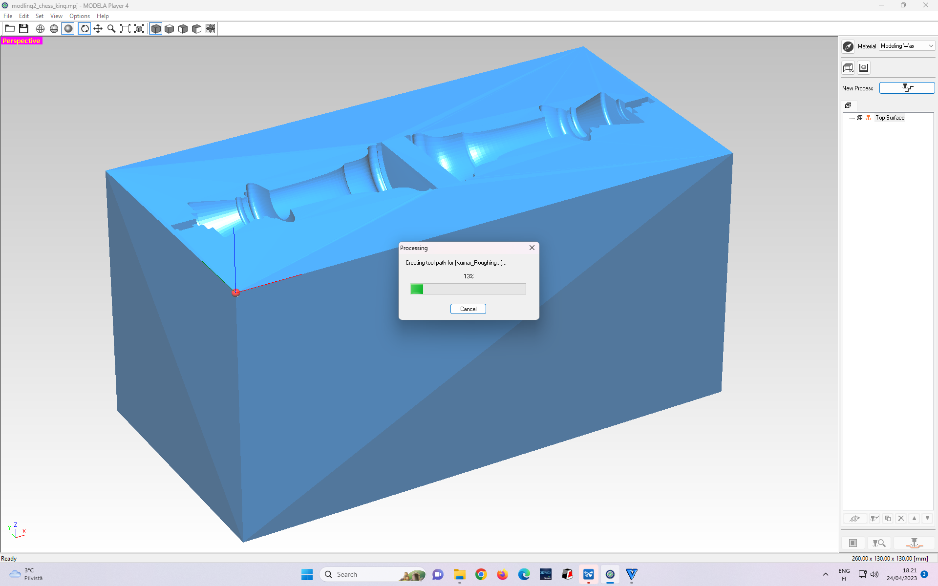 Figure 11: Creating Roughing cut toolpath.
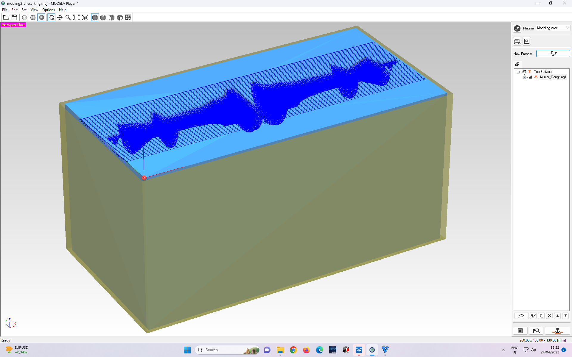 Figure 12: Roughing cut toolpath created
Figures 13 - 20 show the steps to create a finished cut toolchain.
 Figure 13: Selecting “Finishing” cut toolpath profile.
 Figure 14. Next, we need to select the tool with the right diameter matching our tool (blade). I chose 3.18 mm since our tool(blade) had this diameter.
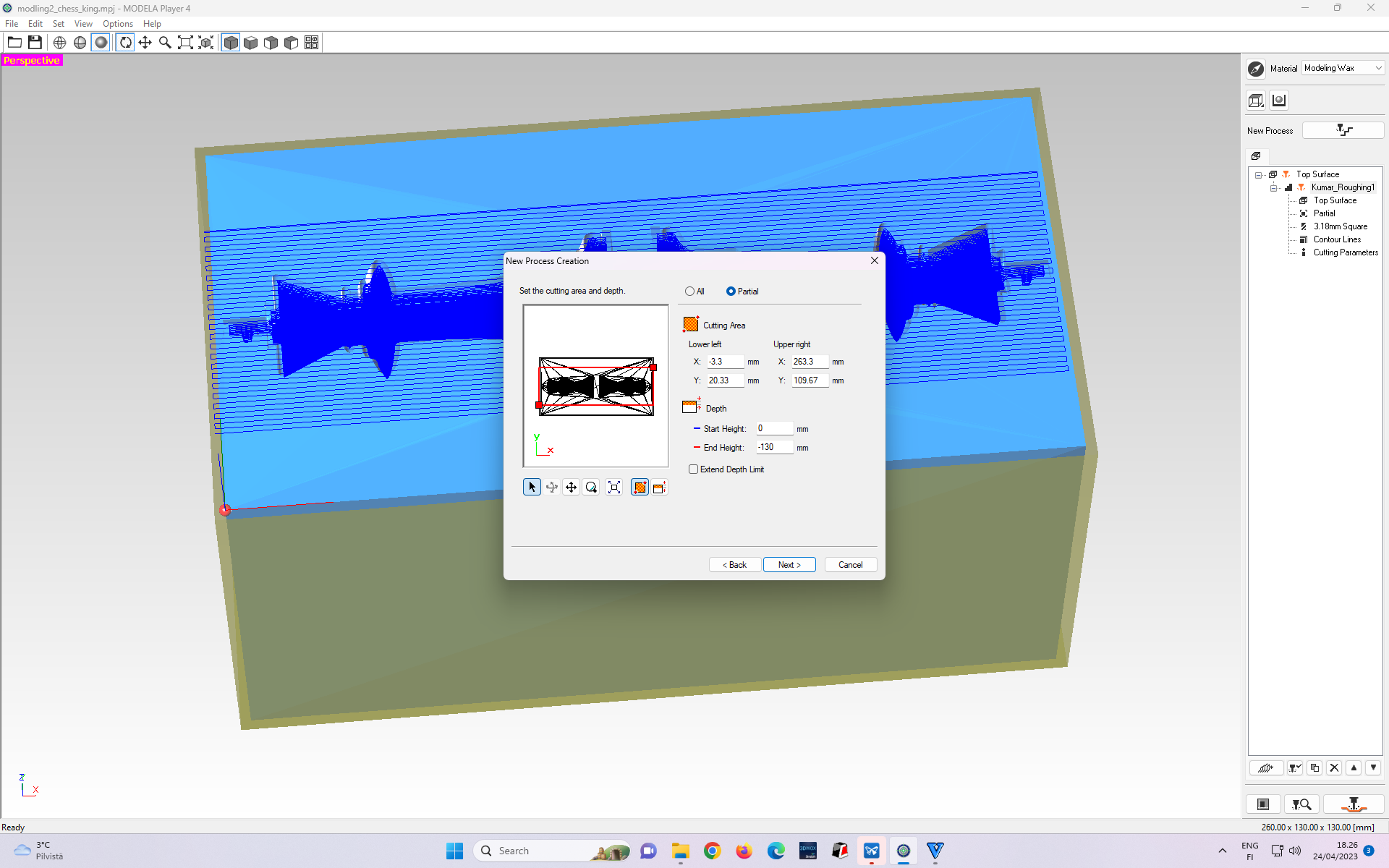 Figure 15: By default, even the area beyond the stock region is within milling coverage. I adjust the area such that milling will be done in the stock region only
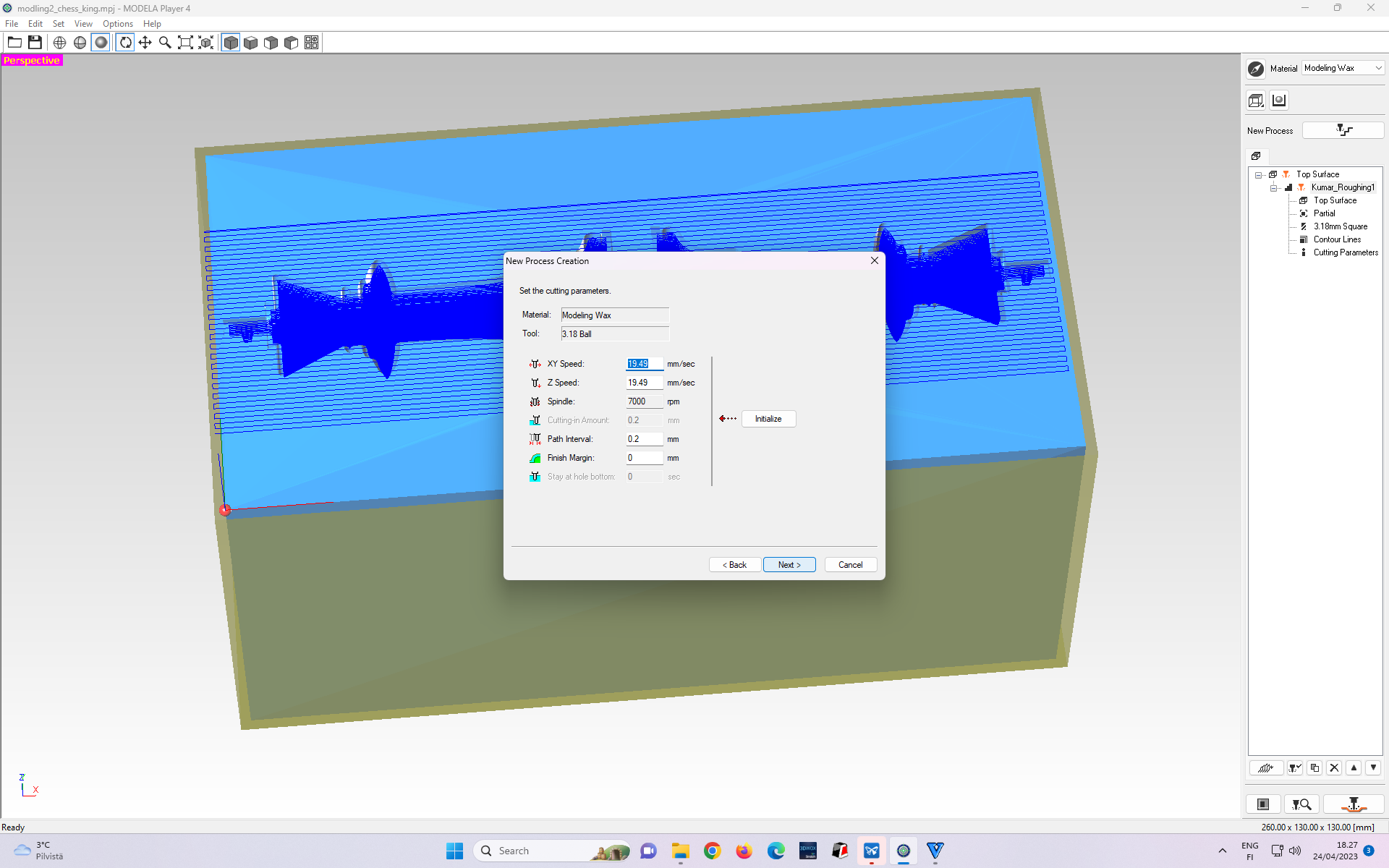 Figure 17. The Dialogue box shows the summary of cutting parameters for finishing cut. If all parameters seem appropriate, we select Next, otherwise, we select “Back” to return to the previous step to modify the relevant cutting parameters
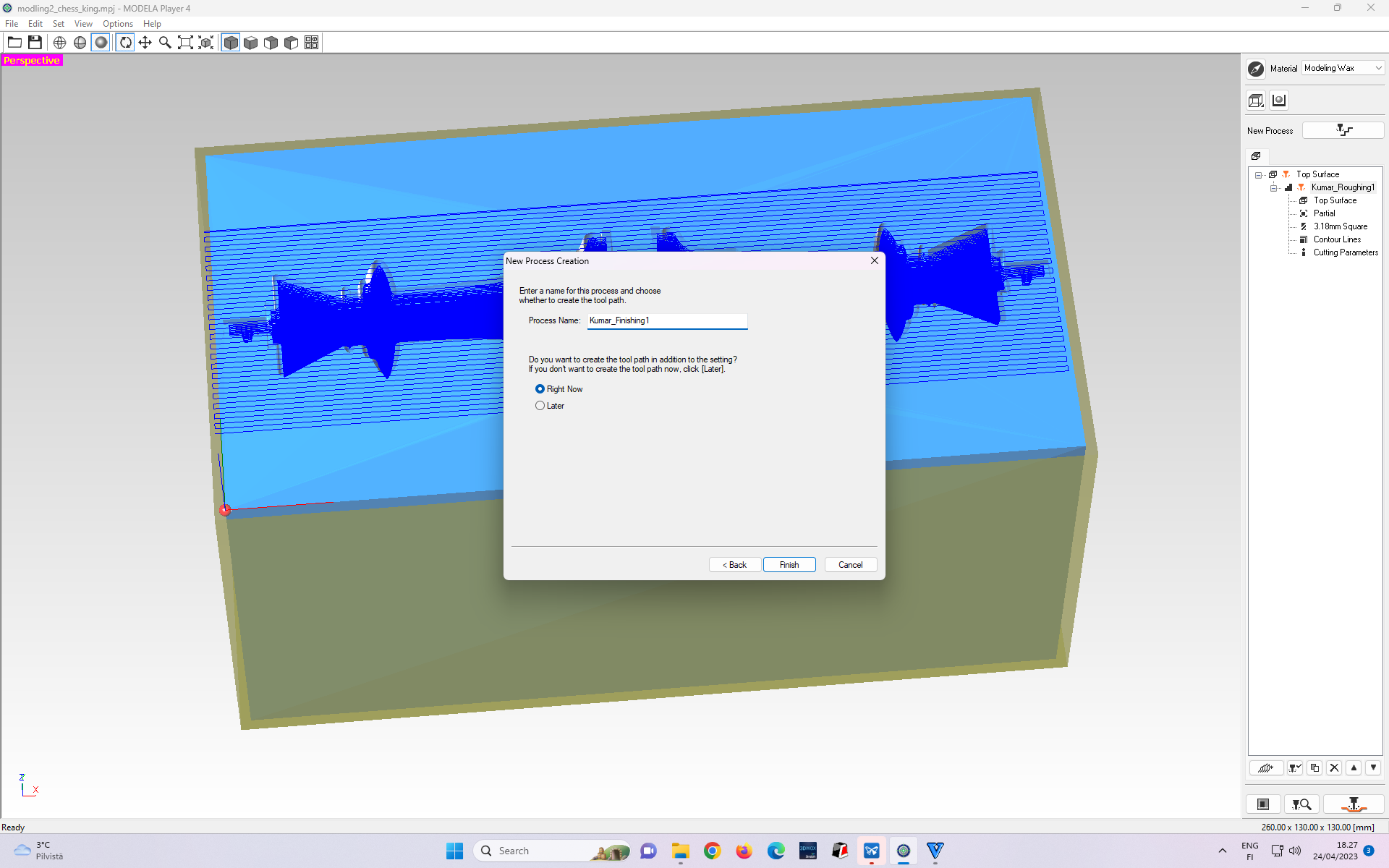 Figure 18: Renaming “Finishing” cut toolpath process
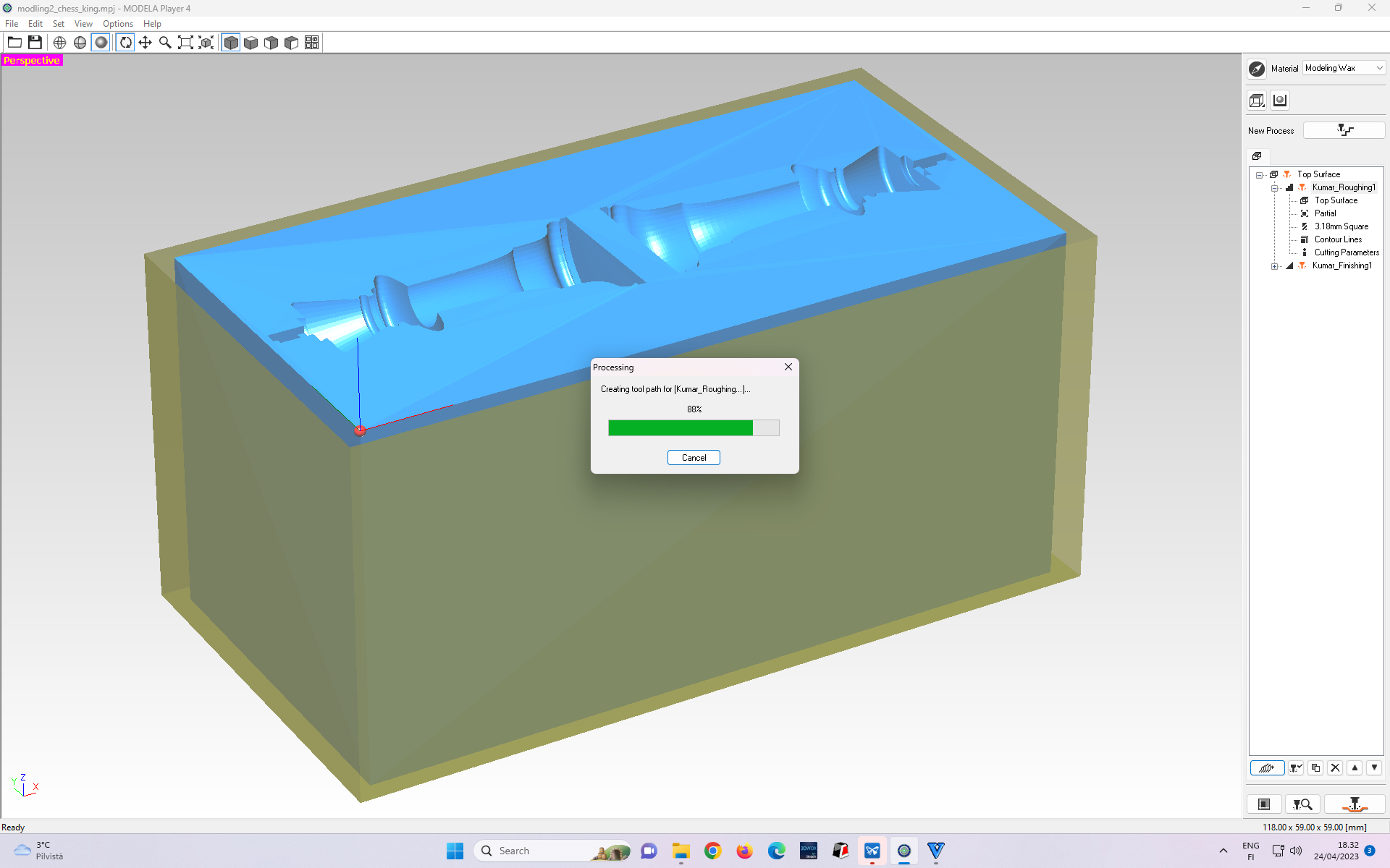 Figure 19: Creating “Finishing” cut toolpath process
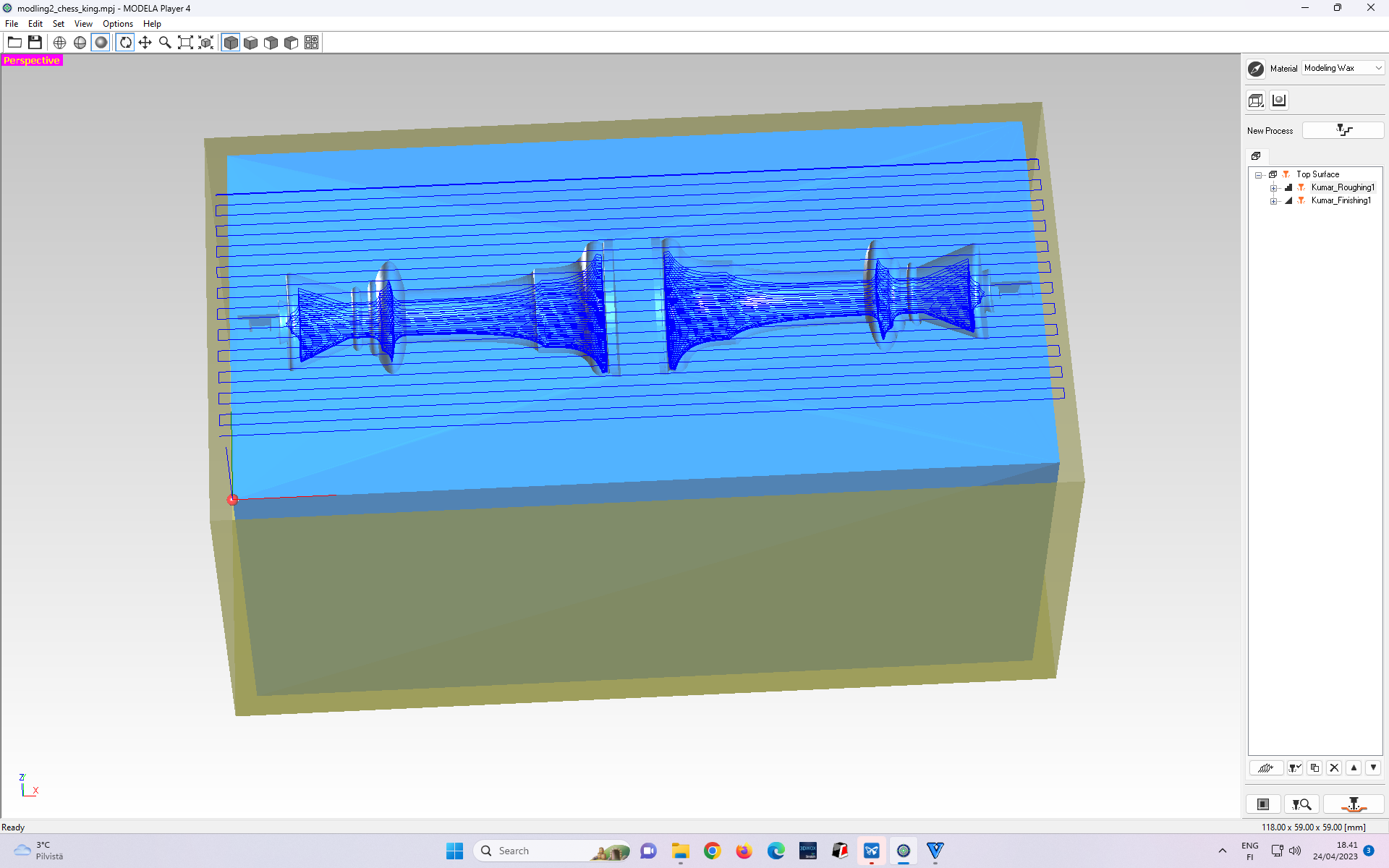 Figure 20: “Finishing” cut toolpath process being created
Figures 21-23 show steps to export toolchain paths to be used for Roland’s milling machine.
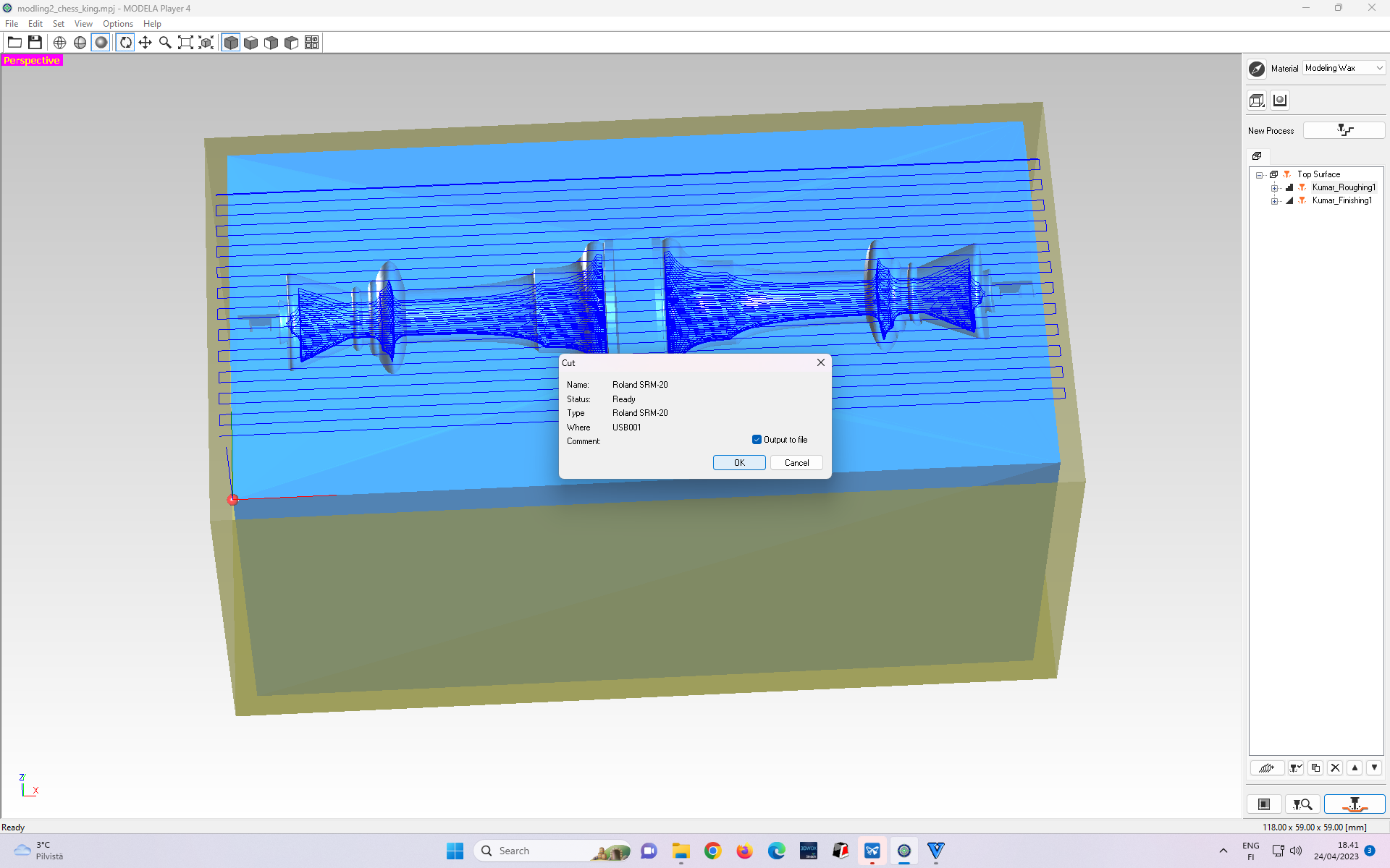 Figure 21 Exporting toolpaths for loading to Roland SRM-20 milling machine
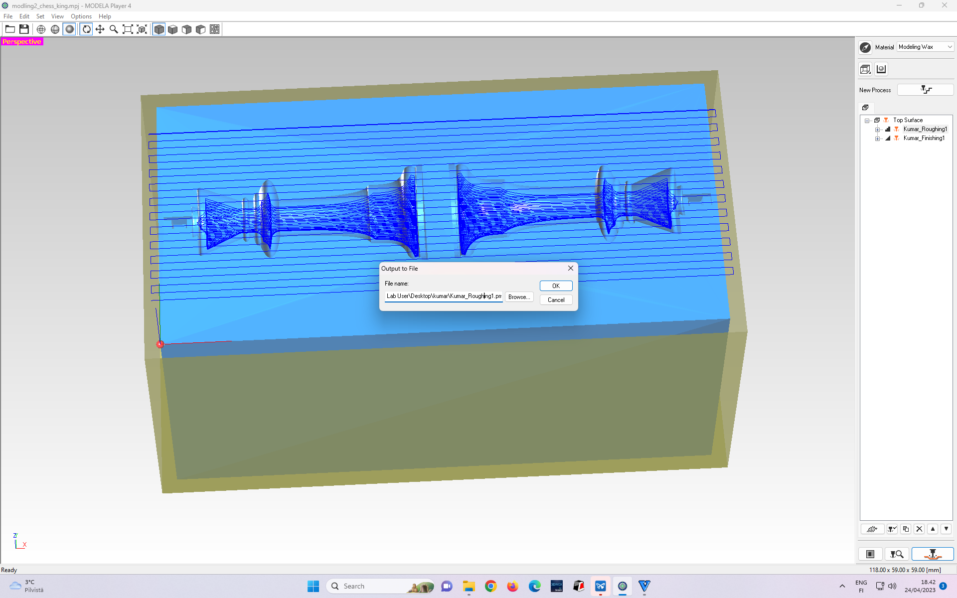 Figure 22: Exporting Roughing cut toolpath to be loaded in Roland for milling
 Figure 23: Exporting Finishing cut toolpath to be loaded in Roland for milling
Mllling wax
We used Roland SRM-20 to mill the blue-coloured wax shown in Figure 24.
For milling, the wax needs to be firmly fixed inside the machine. Figure 24 shows the step where the mold is tapped and hot-glue is applied at its bottom surface facing the Roland. To do this, I applied a painter’s tab on the bottom surface of the wax and the surface inside the machine (shown in Figure 25) on which the wax is to be firmed.
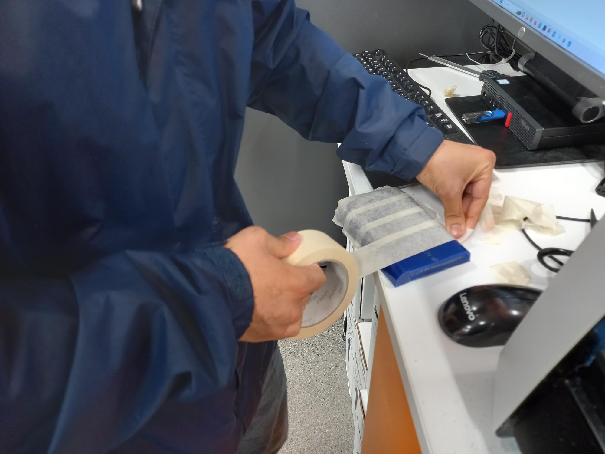 Figure 24: Tapping the wax with a thin sheet, and hot-glue will be applied to the bottom surface.
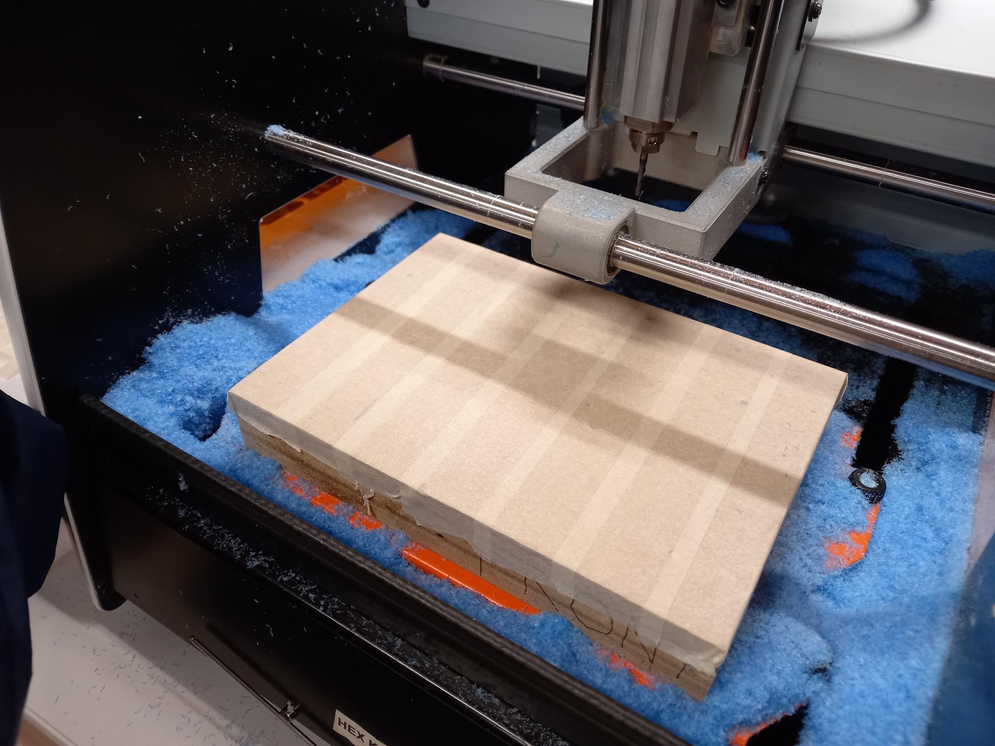 Figure 25: Location surface inside the Roland SRM-20 machine where the mold is to be pasted by hot-glue.
Then, I set (X, Y, Z) origin in Roland.
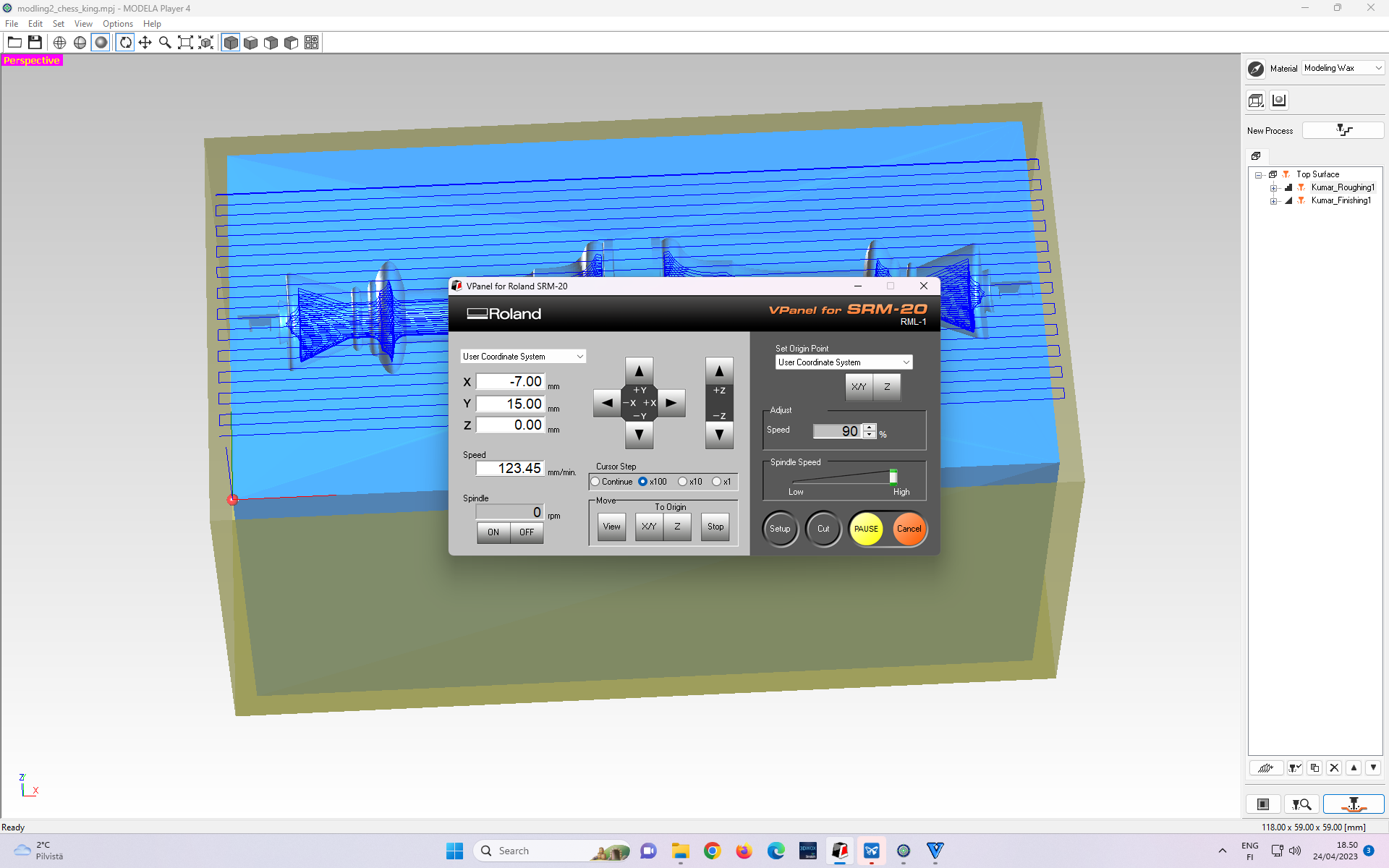 Figure 26: Interface of the MODELA Player Program after importing the (Chess King) STL file.
Figure 27 - 31 shows the steps of loading the rough toolchain in Roland in sequential order.
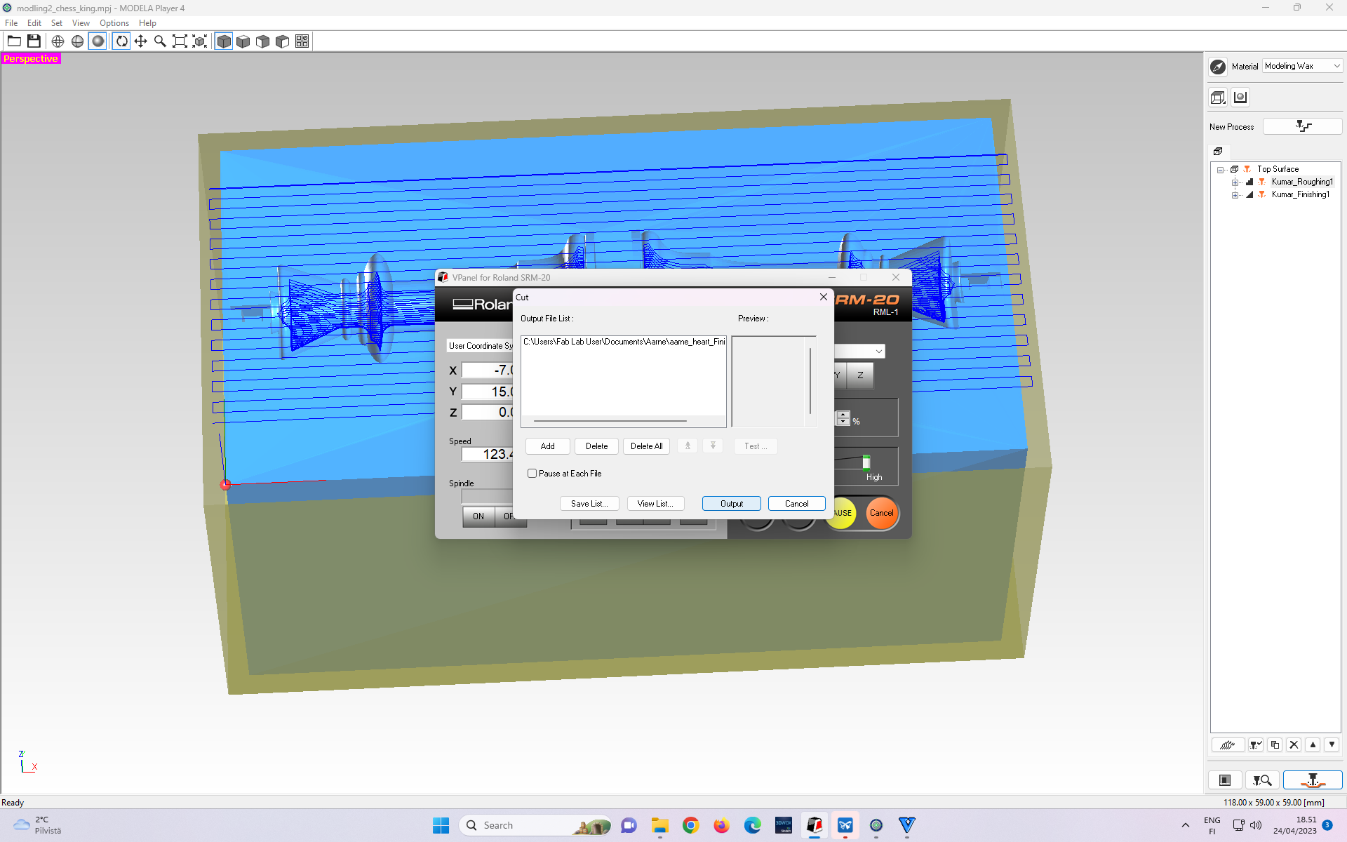 Figure 27: Pressing the “Cut” tab on Roland’s machine display prompts to the toolpath file selection window.
 Figure 28: Toolpath file selection window.
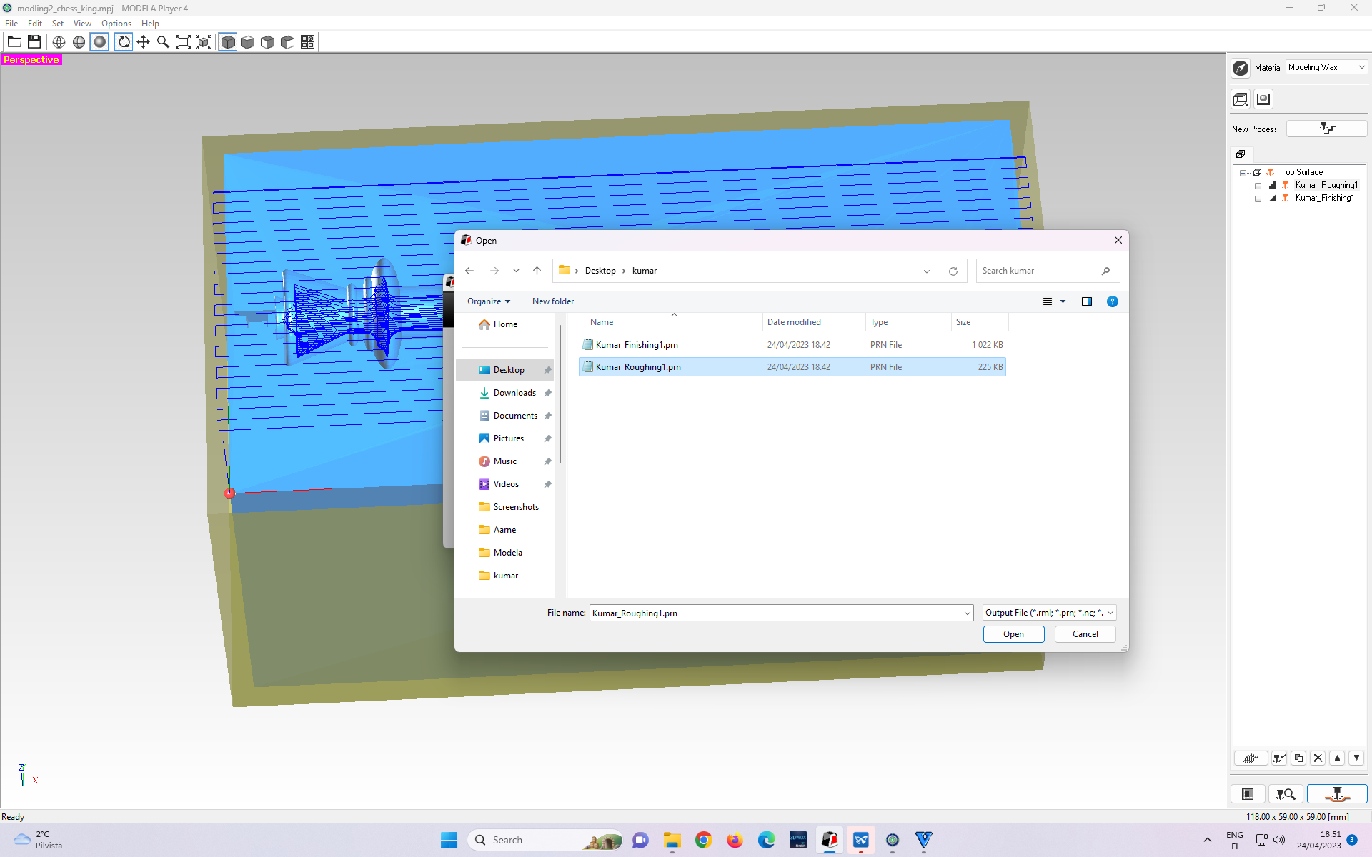 Figure 29: Existing loaded file (if any) needs to be deleted.
 Figure 30: Selecting Roughing toolpath as an Output File.
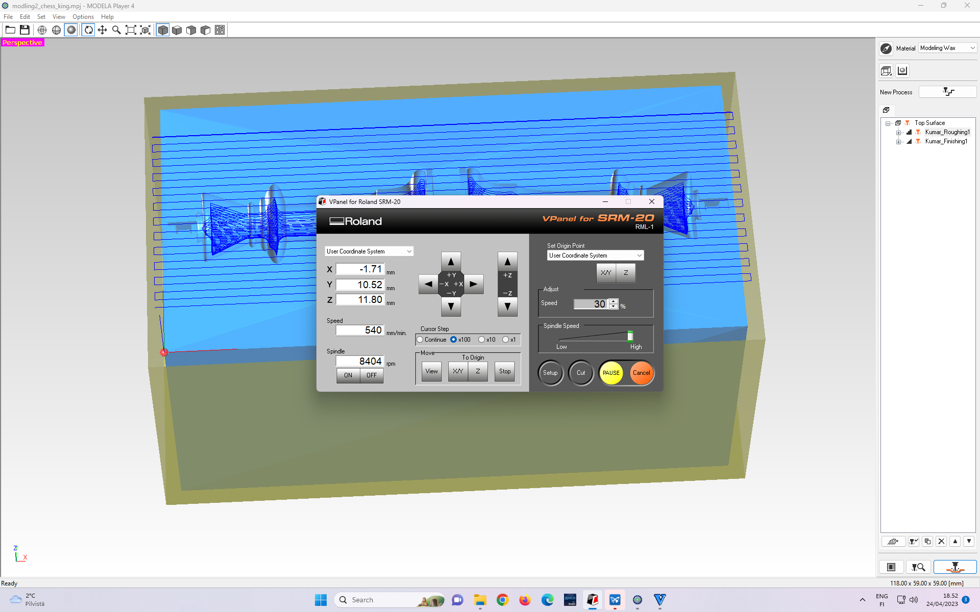 Figure 31: Selecting “Ouput” prompts the milling to begin.
In the beginning, the dilling speed is set to 30% on the right side of the control panel under the “Speed” option with the “Adjust” tab.
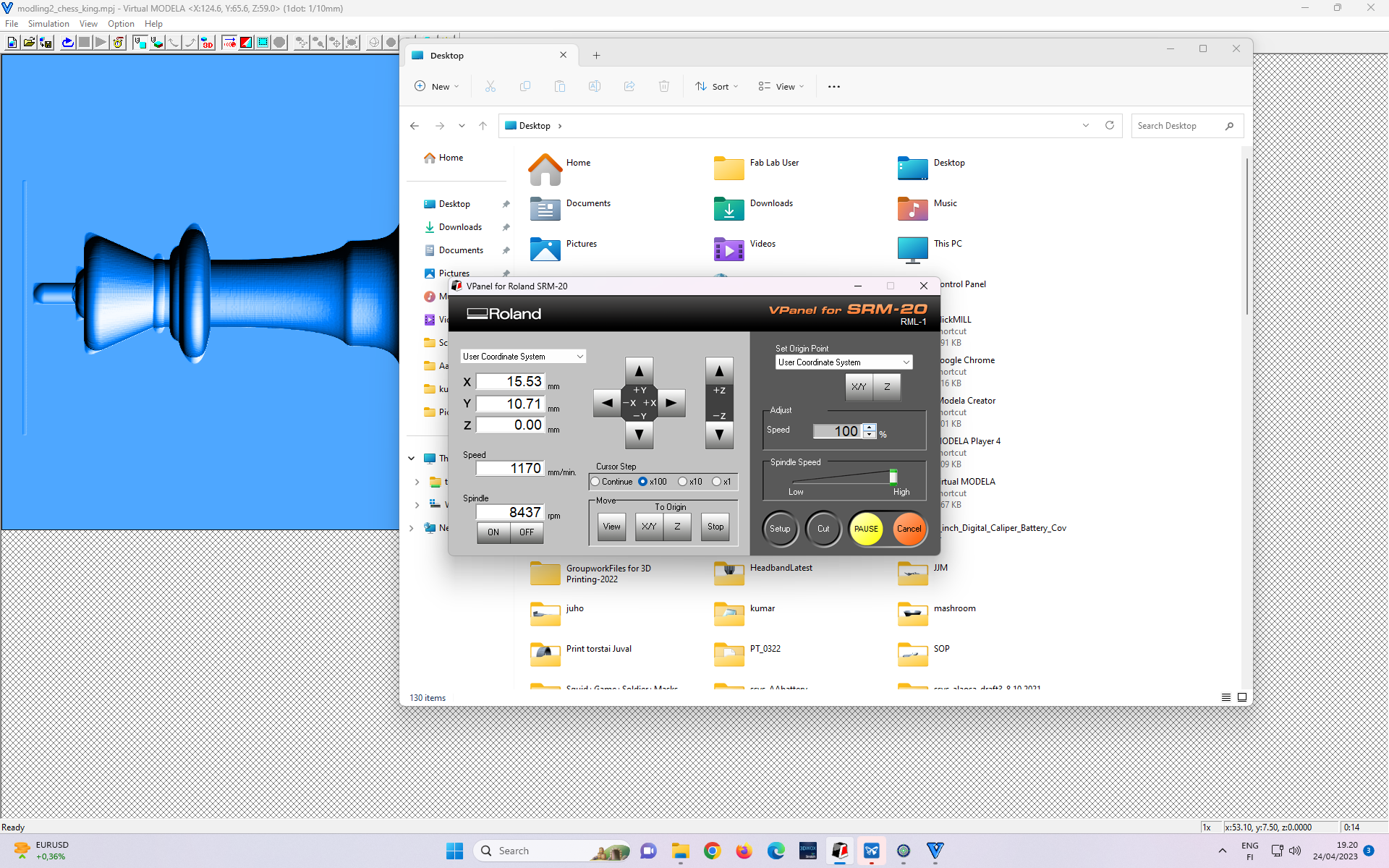 Figure 32: Milling speed increased.
After the first layer is milled out, the milling speed is increased to 100% on the right side of the control panel under the “Speed” option with the “Adjust” tab.
According to our local instructor, it is not necessary to slow down the first layer in general. The reason for doing it is the uneven surface of the wax stock. If the top surface is not even, then there could be areas which are higher than the origin point. While milling those areas milling bit will be cutting more material ==> experiencing more load. With a slower speed, the side load on the milling bit is smaller.
After rough cut finishes, the steps shown in Figure 27 - 31 are repeated, but this time with a finish cut toolchain profile.
Result of the milling process
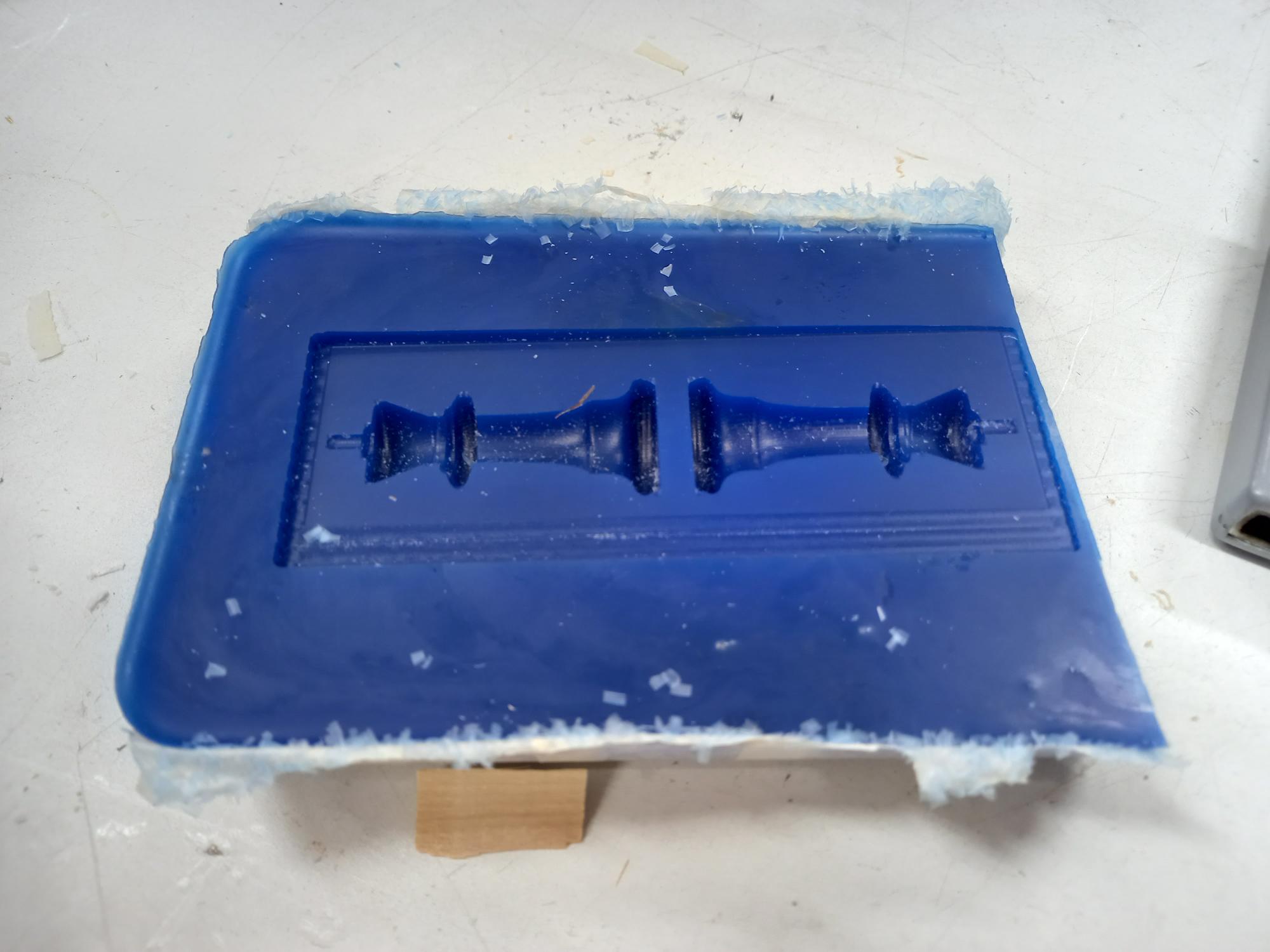 Figure 33: Finished negative mold
As I mentioned before, I made a mistake during making the stock, but it has a rough cut and a finish cut.
Casting
Next, I describe the casting process with the following images (with their captions) in sequential order.
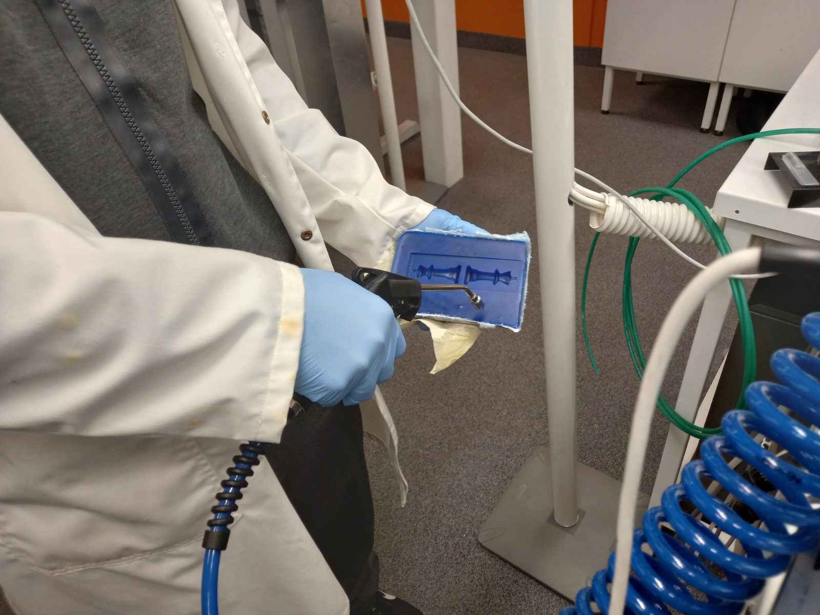 Figure 34: Clearing the stock.
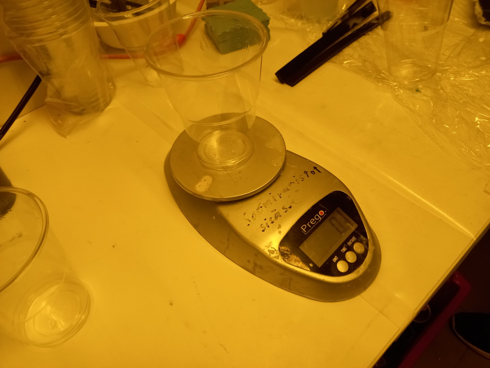 Figure 35: Measuring the initial weight of empty glass.
 Figure 36: Pouring Smooth-SII 936, Platinum Cure Silicone Rubber Part A to the glass.
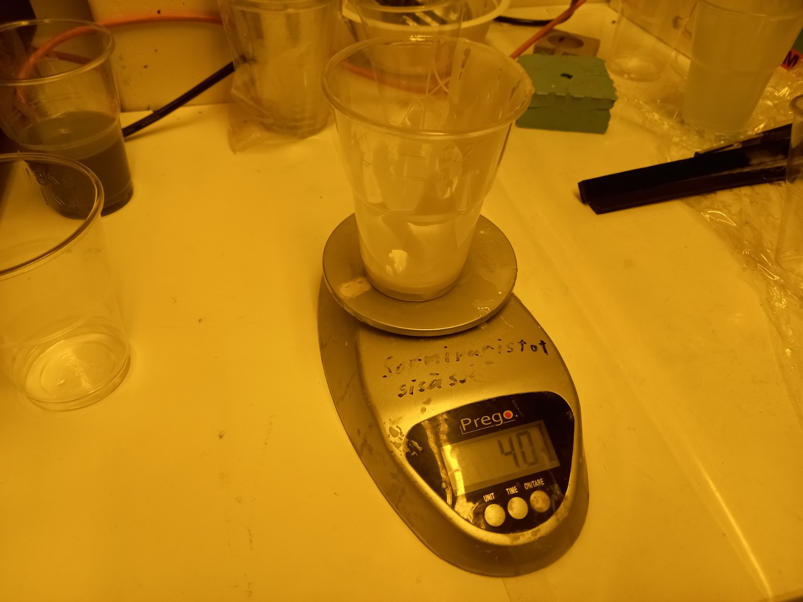 Figure 37: Measuring the glass after pouring silicon into it, poured amount = 40g.
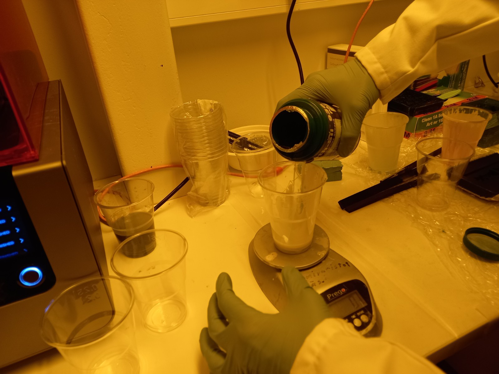 Figure 38: Pouring another liquid Smooth-SII 936, Platinum Cure Silicone Rubber Part B, poured amount = 10% of poured Smooth-SII 936, Platinum Cure Silicone Rubber Part A = 4g.
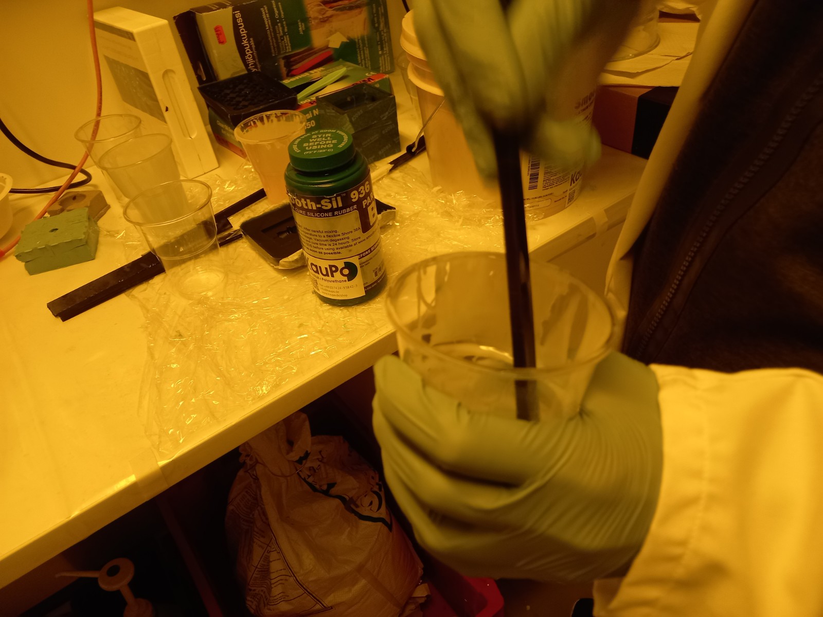 Figure 39: Stirring the mixture in the glass for 8 minutes.
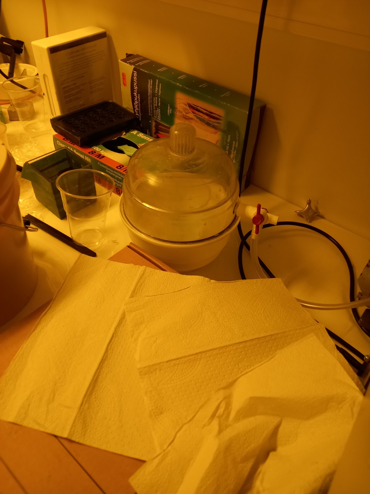 Figure 40: Vacuuming the mixture to remove all the air trapped inside. Waiting until bubbles stop coming out.
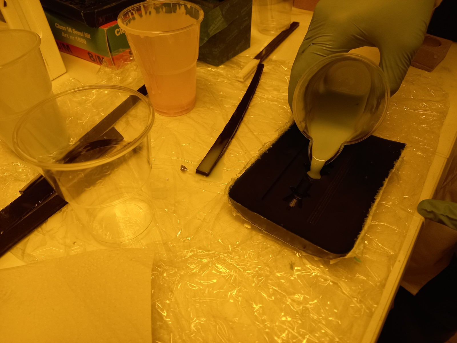 Figure 41: Pouring into the chess stock.
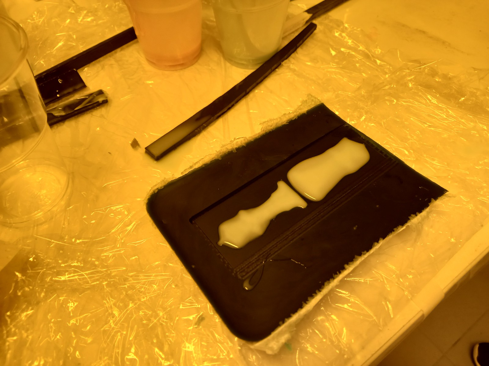 Figure 42: Stock after being poured. Now, then need to be left 24 hours to solidify.
Casted mold
After 24 hours,
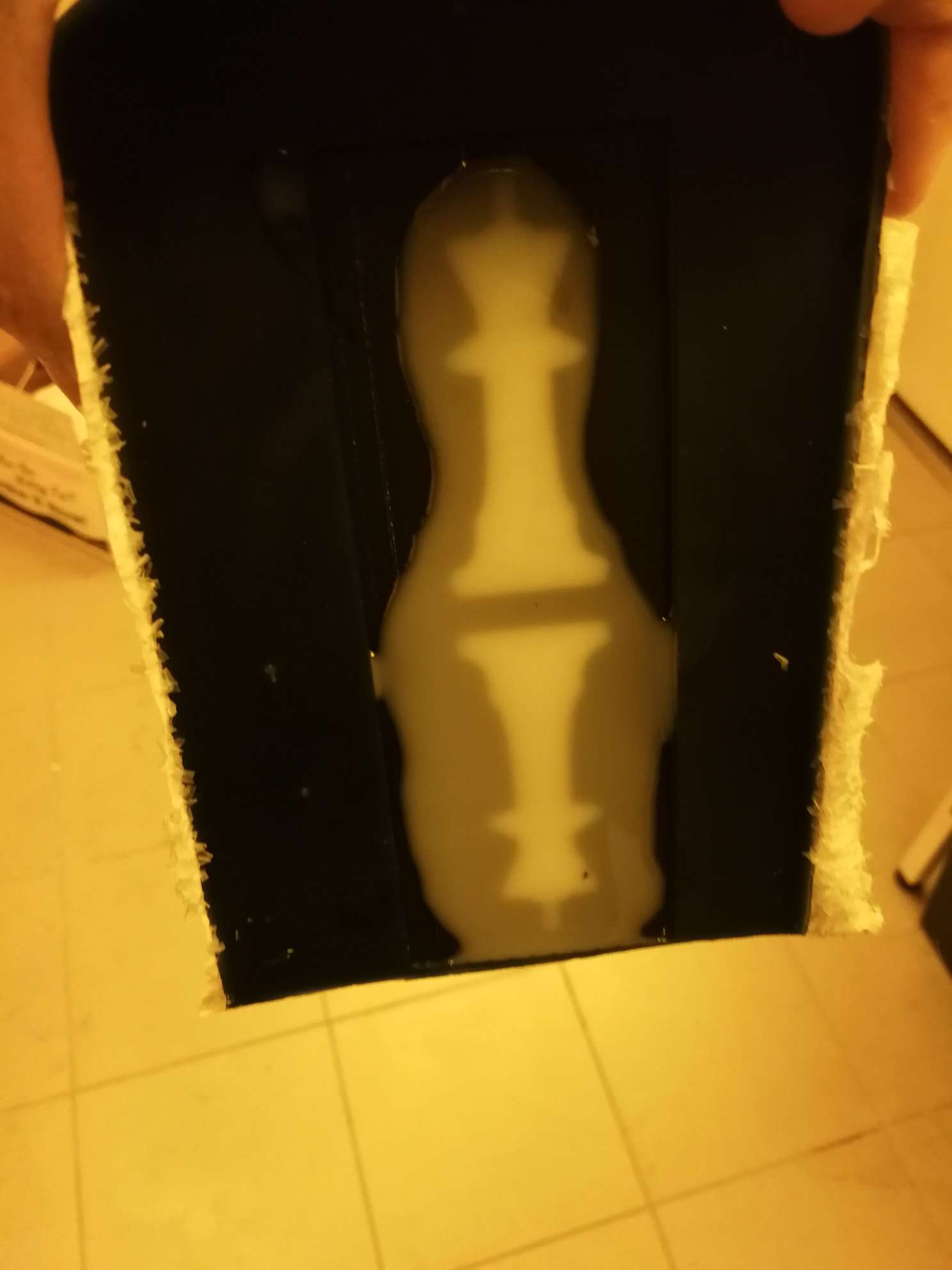 Figure 43: Cured silicone part after 24 hours
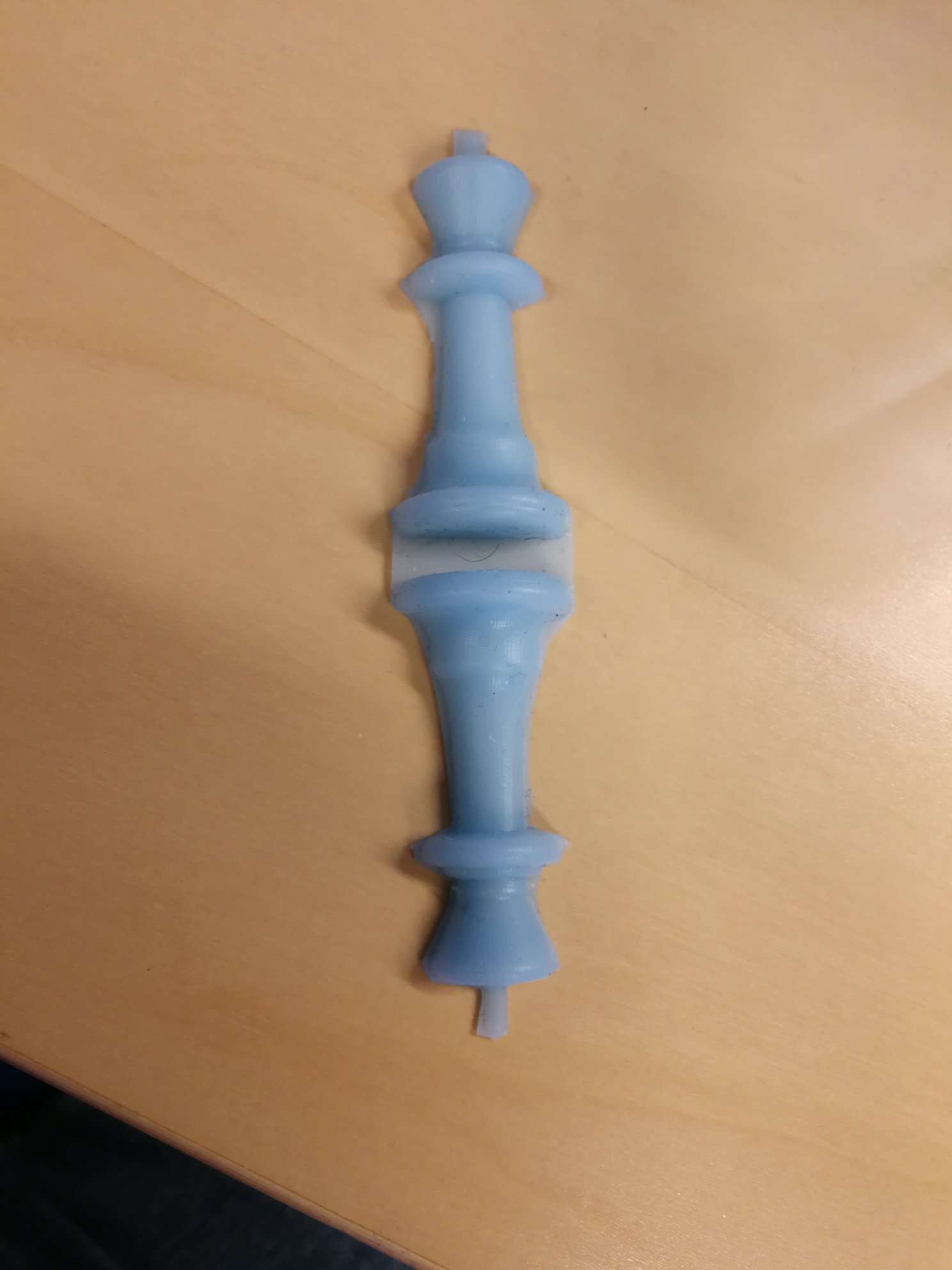 Figure 44: Chess “King” in half after taking out from the mold. No roughness or bubble.
Safety Instructions
- To be used in a properly ventilated area only.
- Wear safety glasses, long sleeves and rubber vinyl gloves required to prevent any contamination.