Final Project
OpenAR for Everyone
This is where I will start defining my final project idea and start to get used to the documentation process.
Background and Motivation
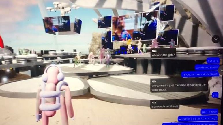 Screenshot of the EU’s metaverse party taken from Vince Chadwick Twitter - Copyright Vince Chadwick @vchadw.
In 2022, the “metaverse” became a major buzzword. However, the adoption of XR (an umbrella term for augmented reality, mixed reality and virtual reality) technologies has been unexpectedly low. For example, the European Union threw a ‘gala’ launch party for its €387,000 metaverse on 05 November 2022 aimed to attract non-politically engaged 18-35 years old, however, only six people showed up for the party. The failure of this event could be attributed to the fact XR devices are not ubiquitous, and the high cost of XR devices does not help at all in their ubiquitous adoption. An open XR system could potentially enable developers to deploy their custom prototypes rapidly and thus would promote innovations. Such innovations are expected to drive the development of low-cost XR devices.
Initial Project Idea
The project is to develop an initial prototype of OpenAR headset Version 3.0 with a budget of 100 euros. It will be built on top of OpenAR Version 1 and work-in-progress OpenAR Version 2.0. The design of OpenAR can be found at: Open Source AR Headset Design which will be followed in my project.
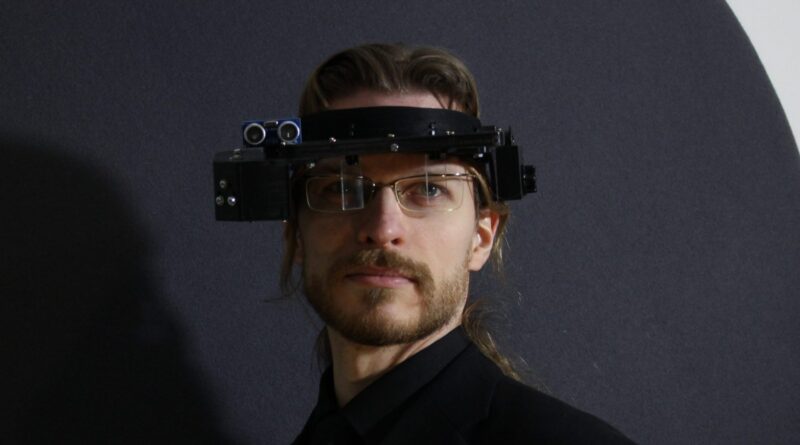 OpenAR Version 1.0 - Copyright Jani Vallirinne.
The project will focus on developing the following features for the next version of the OpenAR headset, with a special focus on Thumb Controller:
- Camera/Display
- AR Thumb Controller
Project: Thumb Controller
In the interest of time, I have decided to narrow down my initial project idea significantly and focus on Thumb Controller. An ideal AR Thumb Controller for 3D interactions should capture and distinguish input data given by the following 10 hand models:
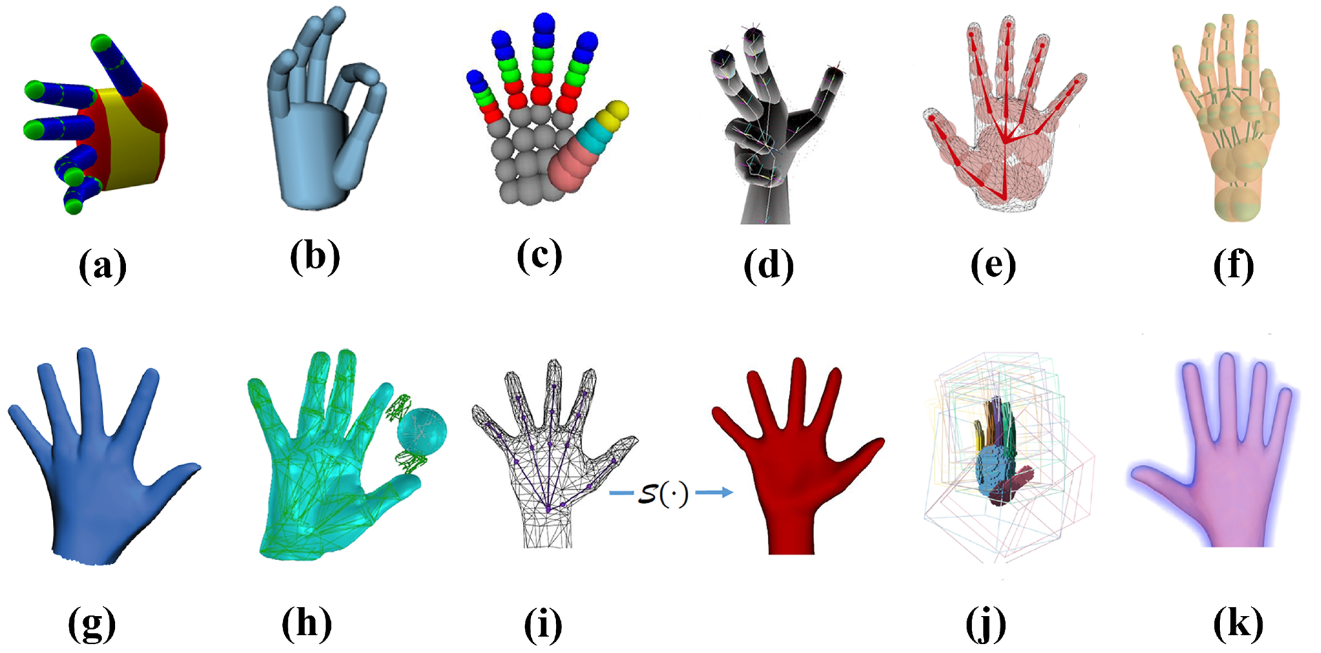 Hand models. (a) Capsule model. (b) Cylinder model. (c) Sphere model. (d) Convex bodies for tracking. (e) Sum of an-isotropic Gaussian model. (f) Sphere-mesh model. (g) Triangular hand model. (h) Triangular mesh. (i) Loop subdivision Surface of a triangular control mesh. (j) Articulated Signed Distance Function (SDF) for a voxelized shape-primitive hand model. (k) Articulated signed distance function for a hand model / Source: Sensors 2019.
For the Fab Academy project, I will focus on Thumb Controller for 2D interactions only, and later extend to 3D interactions. Essentially my Fab Academy project is about building a wireless mouse which can fit in a thumb. Thumb Controller is the integration of the following individual modules:
Final Implementation
Video and Slide
Here is the presentation video of the final result.
And also the slide:
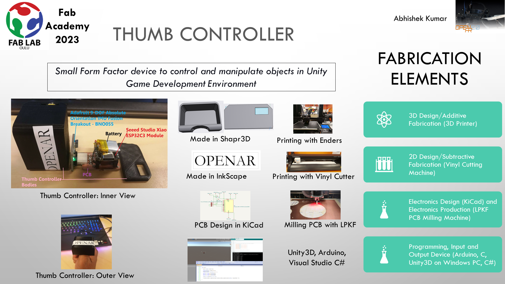
Components of the Project
-
3D Printing/3D Design It is done to create a thumb body for the final packaging, and the process used here is additive printing (aka. 3D printing). It relates to Week 2: Computer-aided Design and Week 5: 3D Scanning and Printing.
-
Subtractive Printing/2D Design It is done to create a logo to be pasted on the body of the thumb controller. It is made by a subtractive fabrication process with a Vinyl Cutter machine. It relates to Week 2: Computer-aided Design and Week 3: Computer-Controlled Cutting.
-
Electronics Design and Production with Seeed Xiao ESP32C3 MCU. It relates to Week 6: Electronics Design and Week 8: Electronics Production. Electronics design is done in Kicad and PCB production is done with the LPKF machine.
-
Embedded System Pipeline: It involves reading input data from IMU Sensors, interfacing the Xiao ESP32C3 Board with Unity on Windows, and showing output on Unity. It relates to Week 11: Input Devices, Week 4: Embedded Programming, Week 9: Output Devices, Week 12: Networking, and Week 13: Interface and Application Programming.
Materials used in the project and the bill
| Qty | Item/Specification | Purpose | Price | Link | Notes |
|---|---|---|---|---|---|
| 1 | TI BQ25100YFPT (Standalone 1-cell, 250-mA linear battery charger with 4.2-V charge voltage and prog. pre-charge) | power supply without need of serial power connection | 1.99 USD | Digikey | Obtained the University of Oulu’s Research Lab |
| 1 | Seeed Studio XIAO ESP32C3 Module | Brain | 4.62 USD | Digikey | Obtained from Fab Lab Oulu |
| 1 | Adafruit 9-DOF Absolute Orientation IMU Fusion Breakout - BNO055 | Sensing orientation of the thumb | 34.95 USD | Adafruit | Obtained from the University of Oulu’s Research Lab |
| 1 | Circuit board material for PCB production (substrate for milling PCB, pinheader, soldering materials) | To fabricate the PCB Board | ~5 USD | Obtained from Fab Lab Oulu |
Additionally, it does require a PC with the Microsoft Windows 10 operating system installed to be able to see the proof of concept.
Note: I had TI BQ25100YFPT Texas Instruments (battery chip) soldered with battery interfaces of Seeed Studio Xiao ESP32C3 module which was able to supply power to the board during the testing phase. Since I didn’t manage to make an untethered thumb controller by the deadline, in the end, it did not make any difference whether the PCB was drawing the power from the serial connection anyway. So, to make tethered thumb controller, one may not need to purchase the external battery chip.
Next, I describe each of the component processes.
1. 3D Printing/3D Design to create thumb body for final packaging
I used Shapr3D software to design the body of the controller. It is graphical software, just like Fusion 360.
For making the body of the thumb controller, I used the original design file (available with Apache 2.0 license) made during the OpenAR project (not by me). But I modified the design file to adapt to my requirement.
However, I designed the door of the thumb controller myself using Shapr3D software. I had to take kerf into account so that it would fit firmly inside the Thumb body.
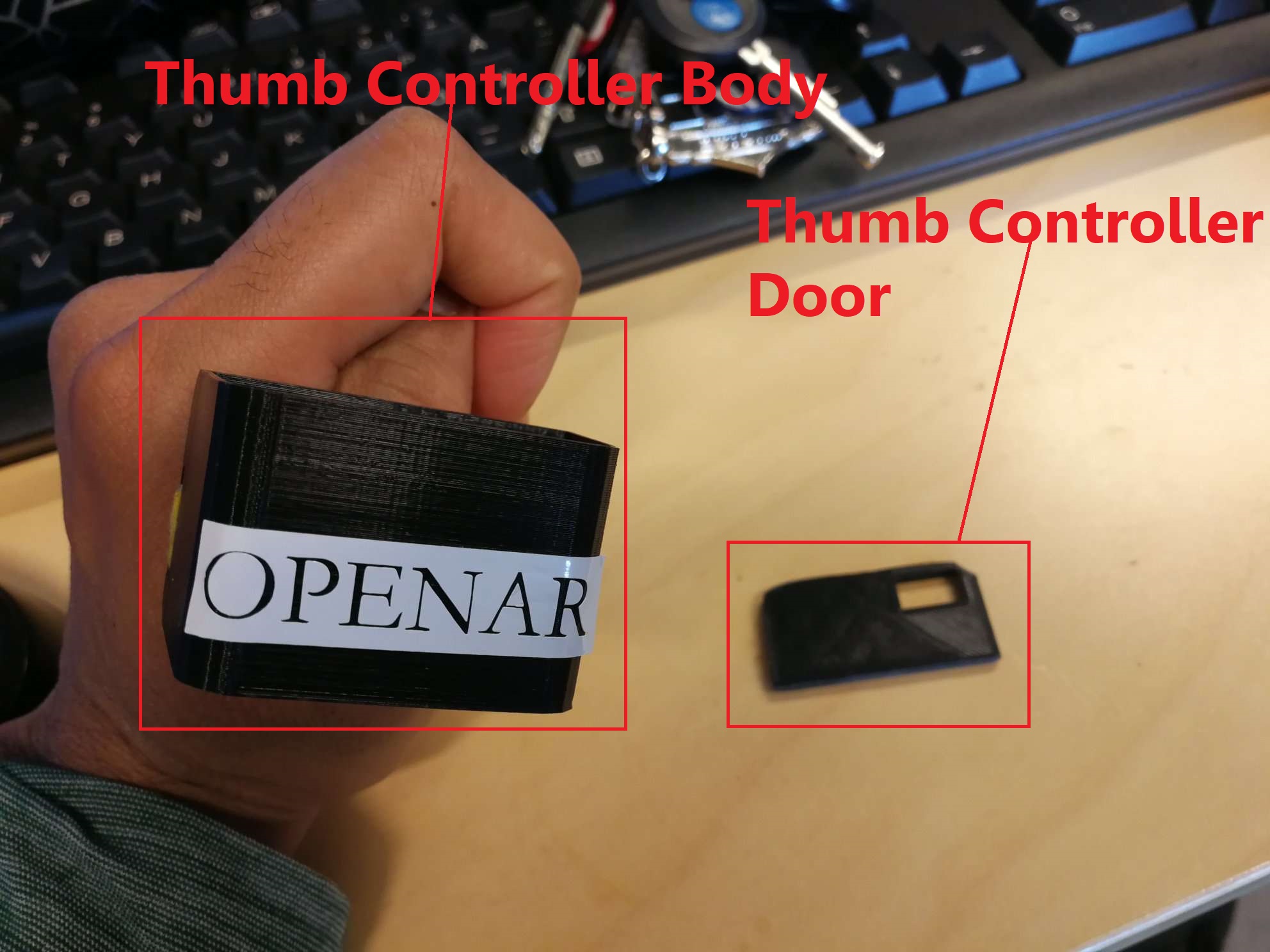
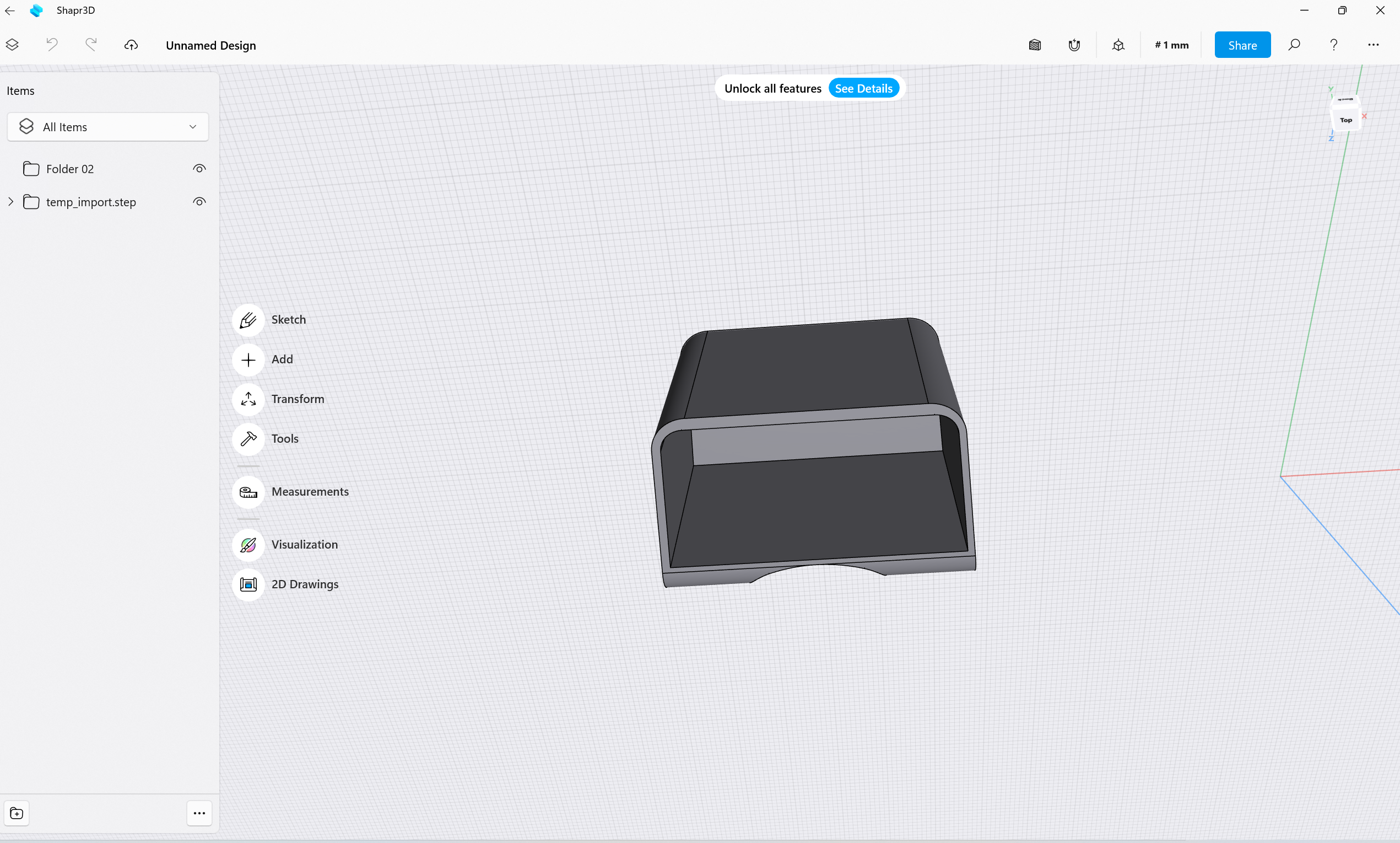 Thumb Controller’s Body which will contain PCB inside
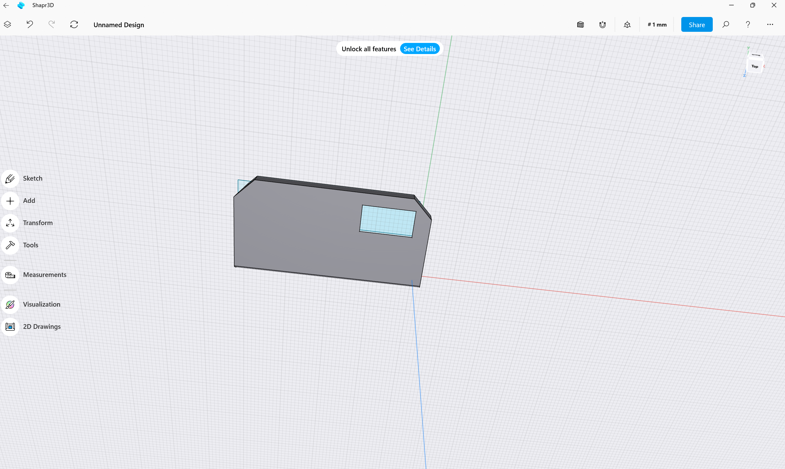 Thumb Controller’s Door with taking kerf into account.
The original editable 3D print file for thumb controllers bodyb(from OpenAR released under Apache 2.0) can be found here
Shapr3D’s free version does not allow exporting the 3D printing file as an editable file. But one can easily adapt it to the required shape from the STEP file provided above by OpenAR as a STEP file.
STL file of Thumb COntroller’s Body after my modifications to adapt to my project’s size requirement can be found here
STL file of the Thumb Controller’s door can be found here
 Thumb Controller’s bodies after 3D printing
2. Subtractive Printing/2D Design to create a logo sticker to be pasted on Thumb Controller’s body
I made one with Inkscape for Week 2 assignment. Logo Sticker
3. Electronics Design to make the PCB design
I designed PCB in Kicad. Kicad design files can be found here
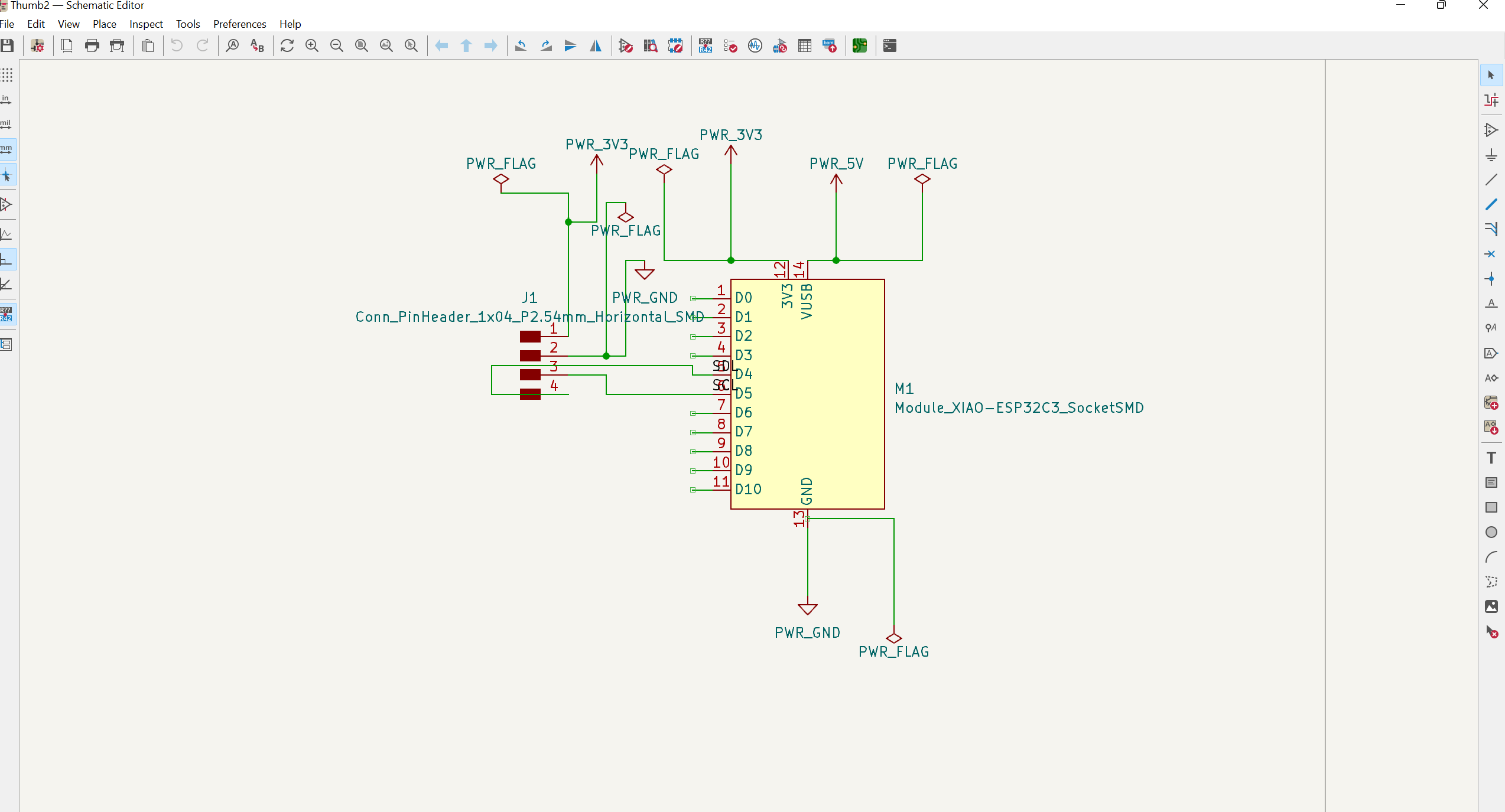 PCB Schematics in KiCad
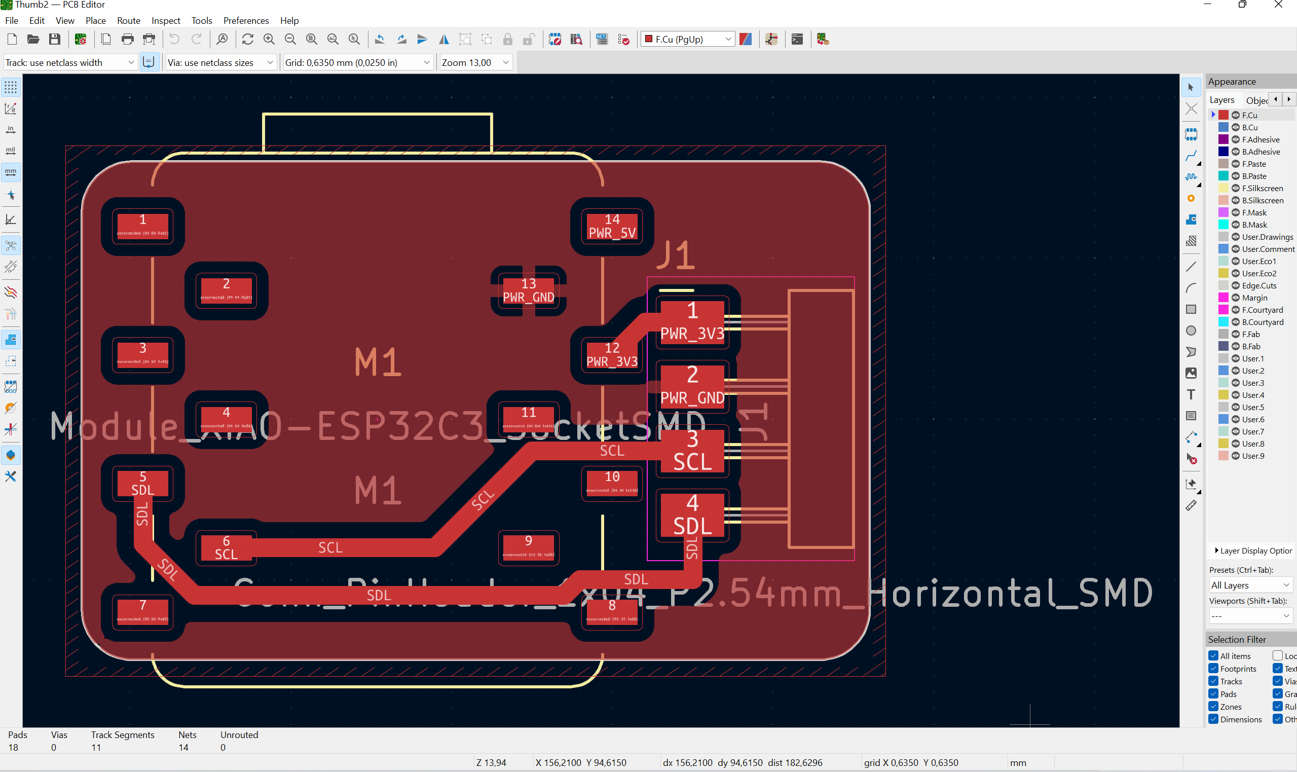 PCB Design Layout in KiCad
4. Electronics Production to fabricate the PCB board
PCB was fabricated with an LPKF machine. Afterwards, I needed to do soldering to attach pin-header connectors on the board.
I also needed to solder the battery chip on the Xiao module itself. The battery chip comes with two wires: red coloured and black coloured. The red coloured wire needs to be connected to the positive terminal on the Xiao module, and the black coloured wire needs to be connected to the negative terminal on the Xiao module. The layout of the battery connector on the Xiao module can be seen at the back side of the module as follows:
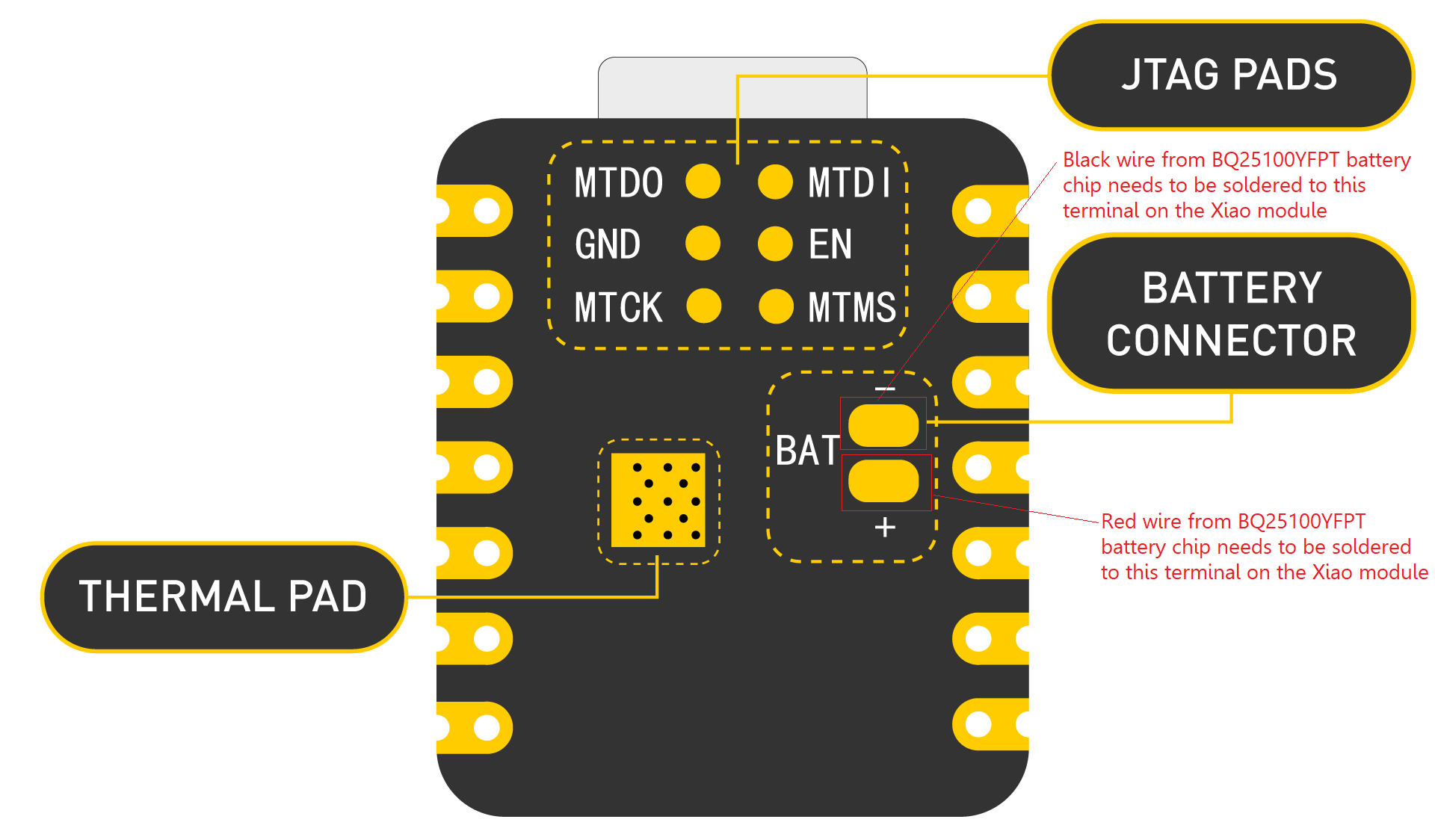 Battery Connector Terminals on the Xiao Module. Image Copyright @Seeedstudio
When the Xiao module is connected to the PC via a serial connection, it draws power from the serial connection, and in the meanwhile battery chip gets charged. When the Xiao module is not connected to the PC via a serial connection, it draws power from the battery (if it has enough charges). It takes about 30 min for the battery to get fully charged.
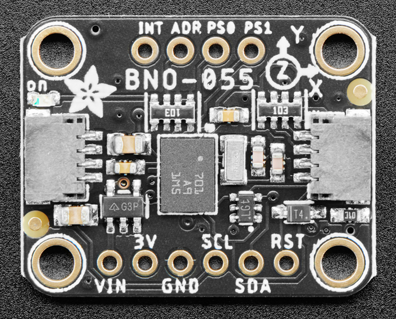 Pinout of Adafruit 9-DOF Absolute Orientation IMU Fusion Breakout - BNO055 . Image Copyright @Adafruit
3V, GND, SCL, and SDA pins of the BNO055 were connected to the corresponding pins of the Seeed Studio Xiao ESP32C3 module via a horizontal pin header on the PCB. Other remaining pins of the BNO055 were not used.
Here is the screenshot after PCB fabrication.
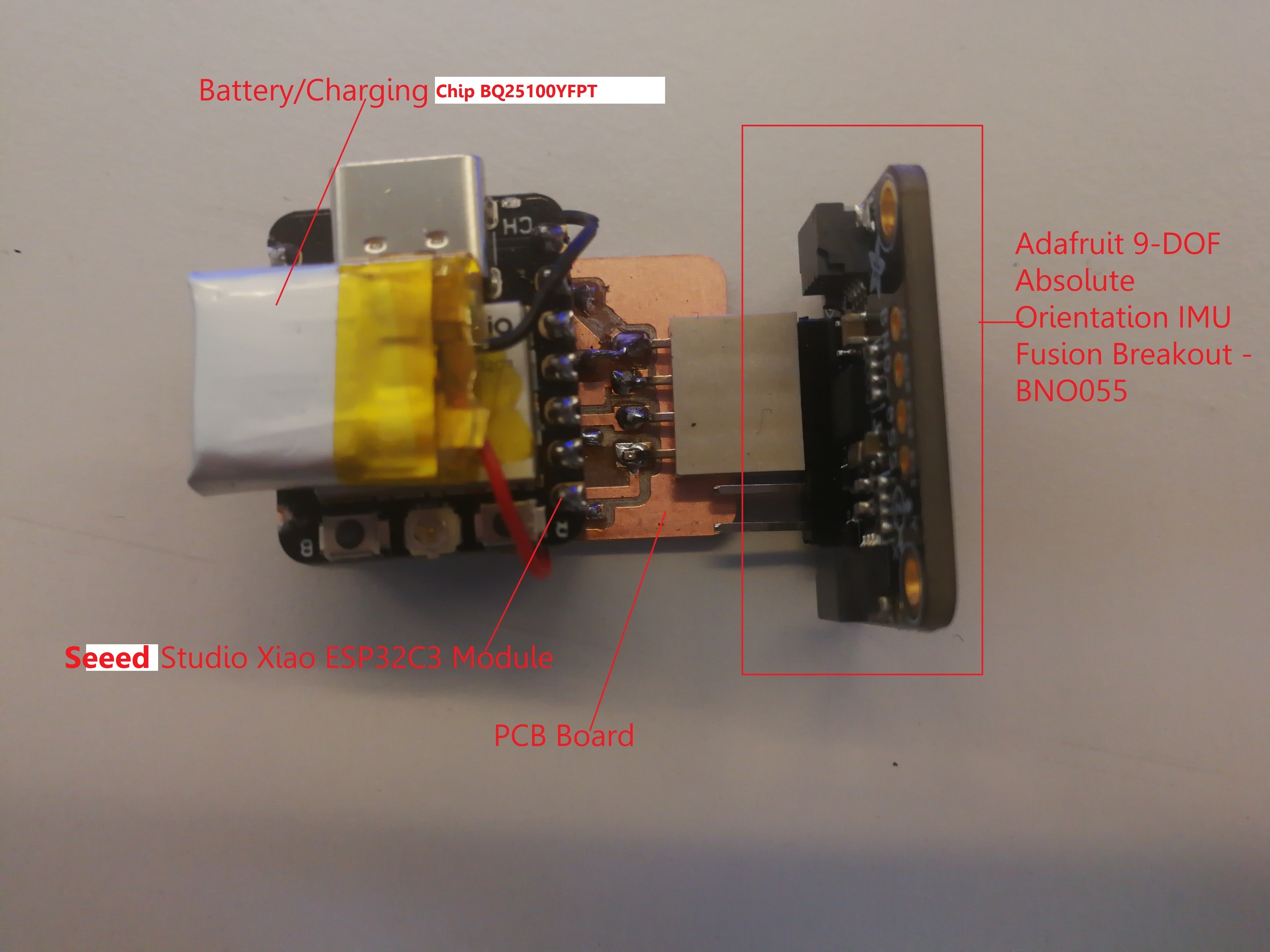 Final Fabricated PCB with Seeed Studio Xiao ESP32C3 module
5. Final Packaging
I did the final packaging with the help of thumb controller bodies made via 3D printing.
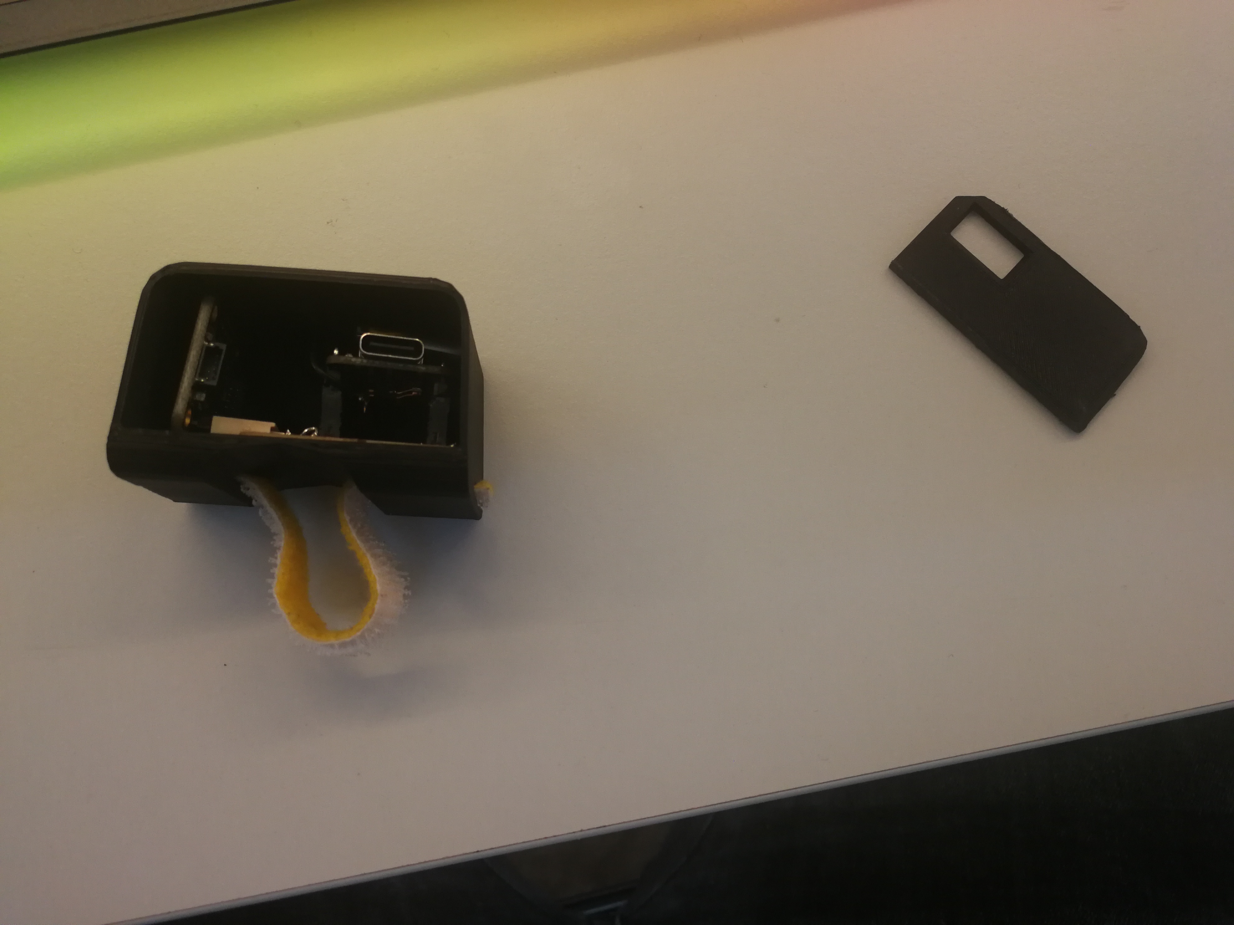 PCB board inside the Thumb controller body and the door separated.
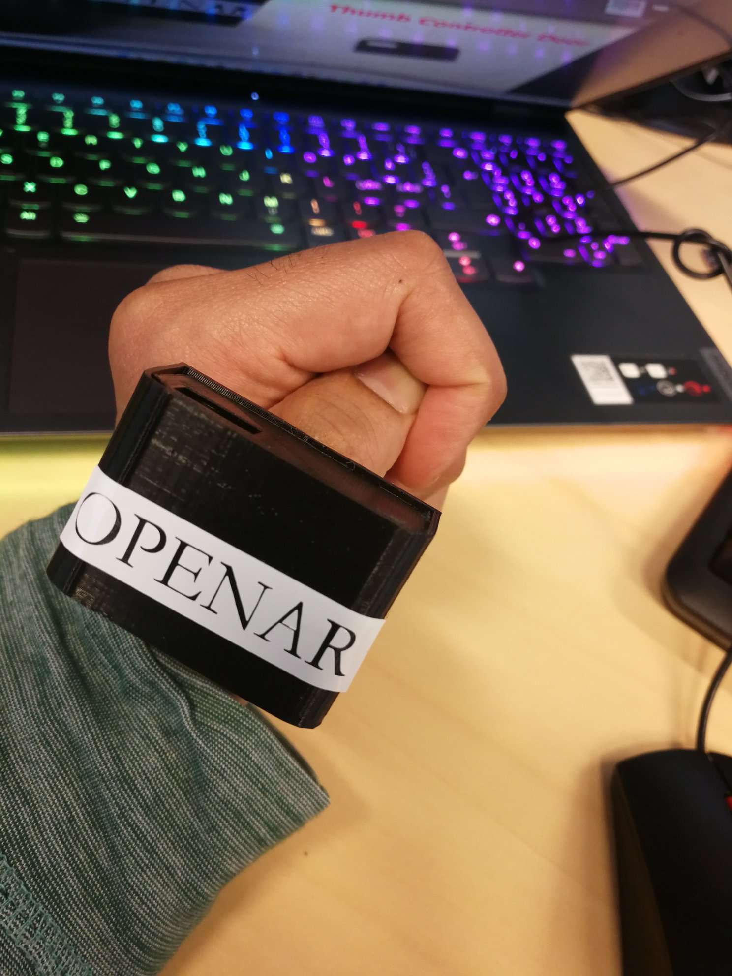 PCB Board packaged within thumb controller body and door.
6. Embedded System Pipeline
I did my final project demonstration by manipulating a cube in Unity3D. It requires interfacing Arduino with Unity3D. I used a serial connection to do this interfacing.
Arduino code to read IMU data can be found here
C# code to interface the thumb controller with Unity can be found here
The entire unity project (size around 40 MB) can be found here.
To replicate the project, one just needs to download the Unity project and build the project. It will generate an exe file.
SerialPort stream = new SerialPort("portnumber", 9600);
- Check the port number in Arduino IDE to which the thumb controller is connected to the computer, and replace the port number here in this code in the ArduinoCtrl.cs file within the Assets folder of the Unity Project (if different). One can also modify the Baud rate. If changes were made to any file of the Unity project, build the project. It will generate a .exe output file.
- Run the exe file (it runs the unity project).
Afterwards, one can wear the thumb controller on their thumb and manipulate the object in Unity. Please refer to the demo video above for a sample.