2. Computer-Aided Design
This week I got acquainted with various software tools for making/editing 2D (raster, vector), 3D types of images, animation, simulation, and techniques for compressing images and videos.
2D Design: Raster Image (with Gimp)
I will show basic edit operations in Gimp, and I will use the following image which I took last year during my trip to Spain.
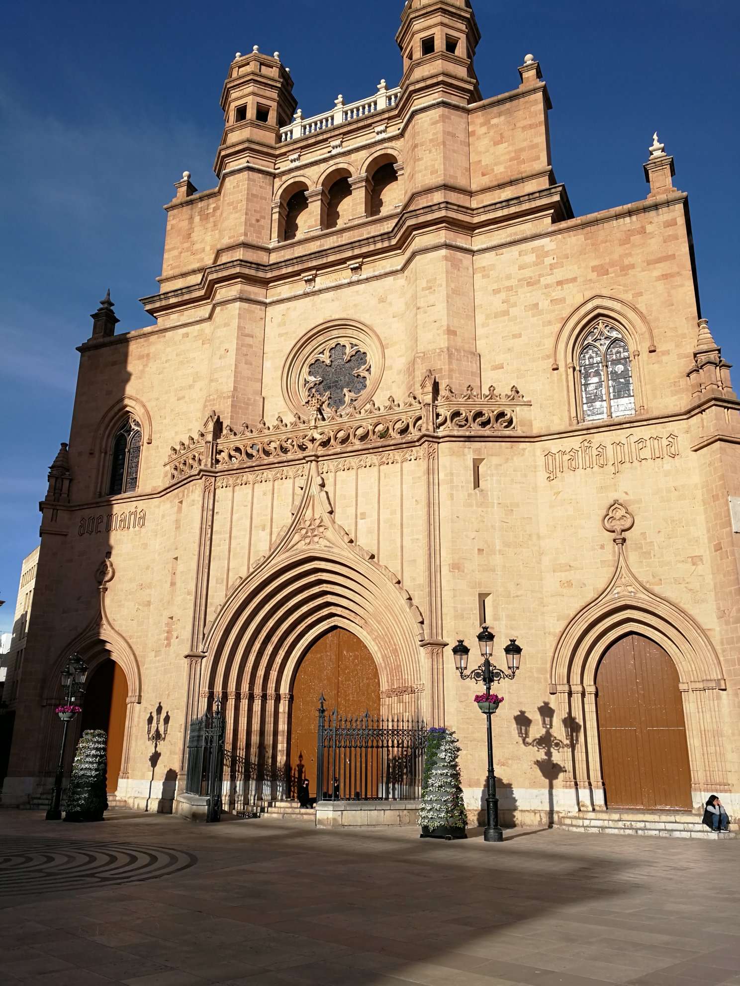 Figure 1: Sample Raster Image.
Next, I will show how to crop the image so that only desired part is in the final image.
Cropping
I will crop the image such that only the material structure is in the final image, and no person is there, which is right now in Figure 1 (bottom right corner). The steps are in the following Figures 2-3 and their captions.
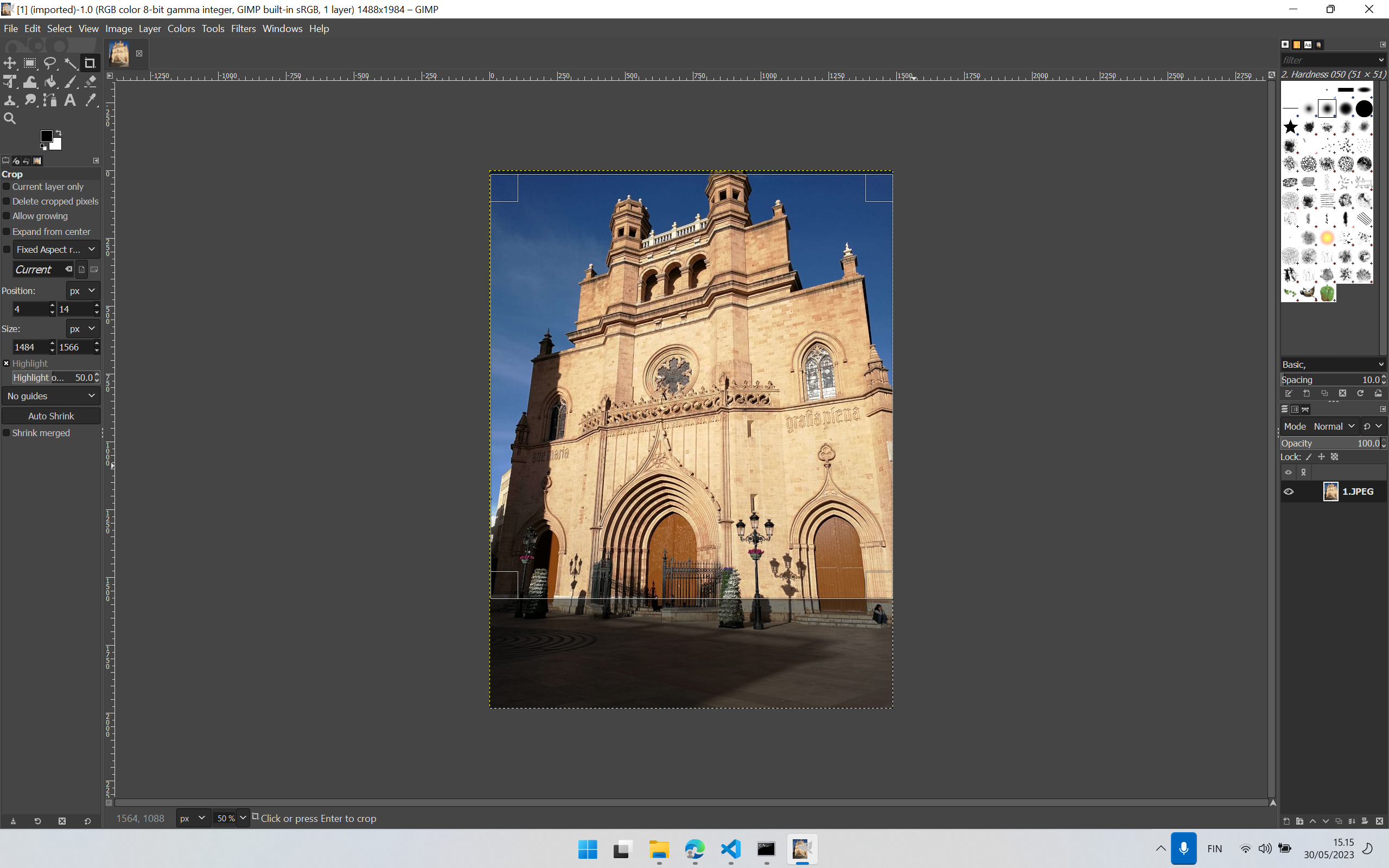 Figure 2: Selected the desired segment in the final image.
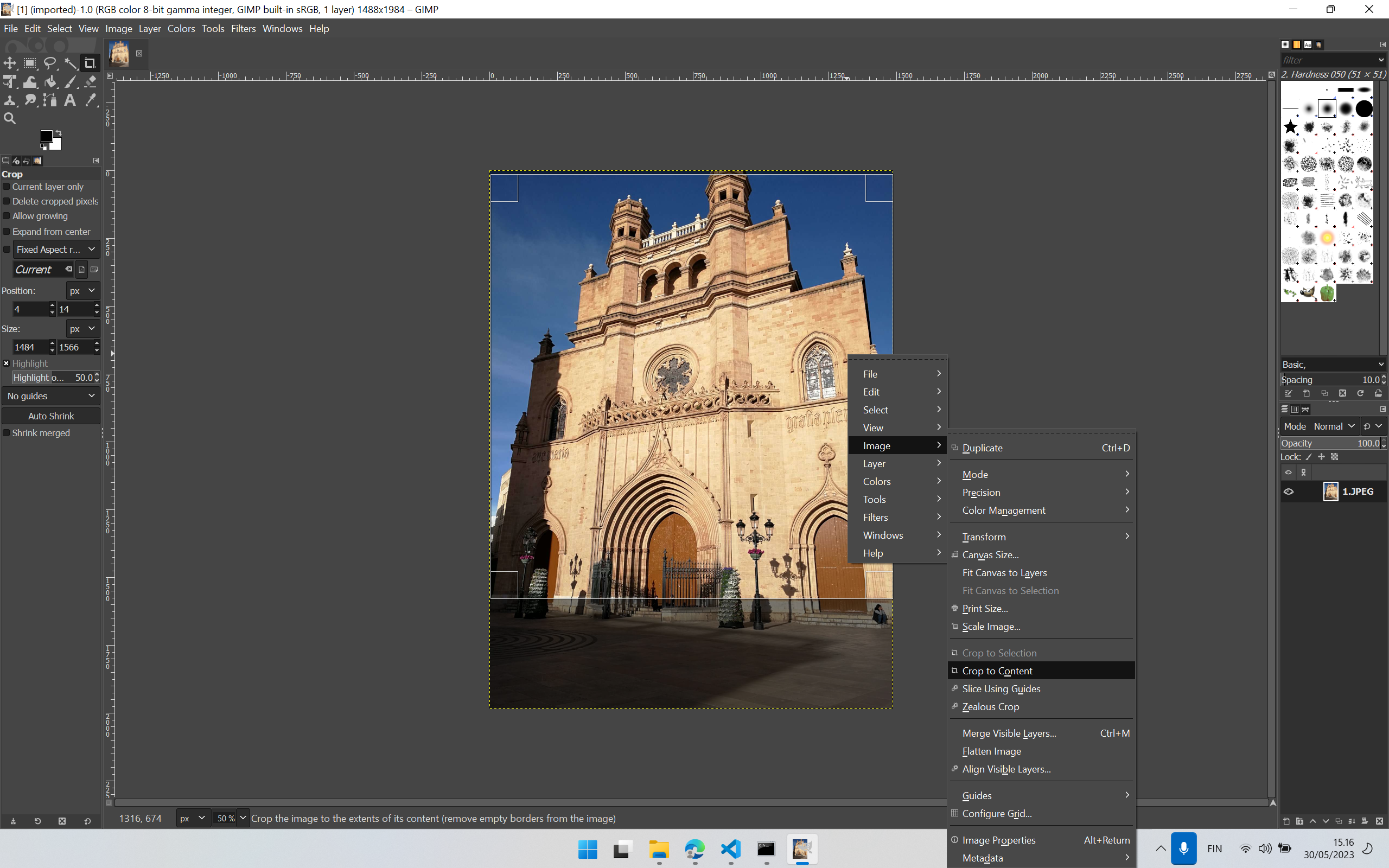 Figure 3: Steps: Right Click -> Image -> Crop to Content.
Cropped Image
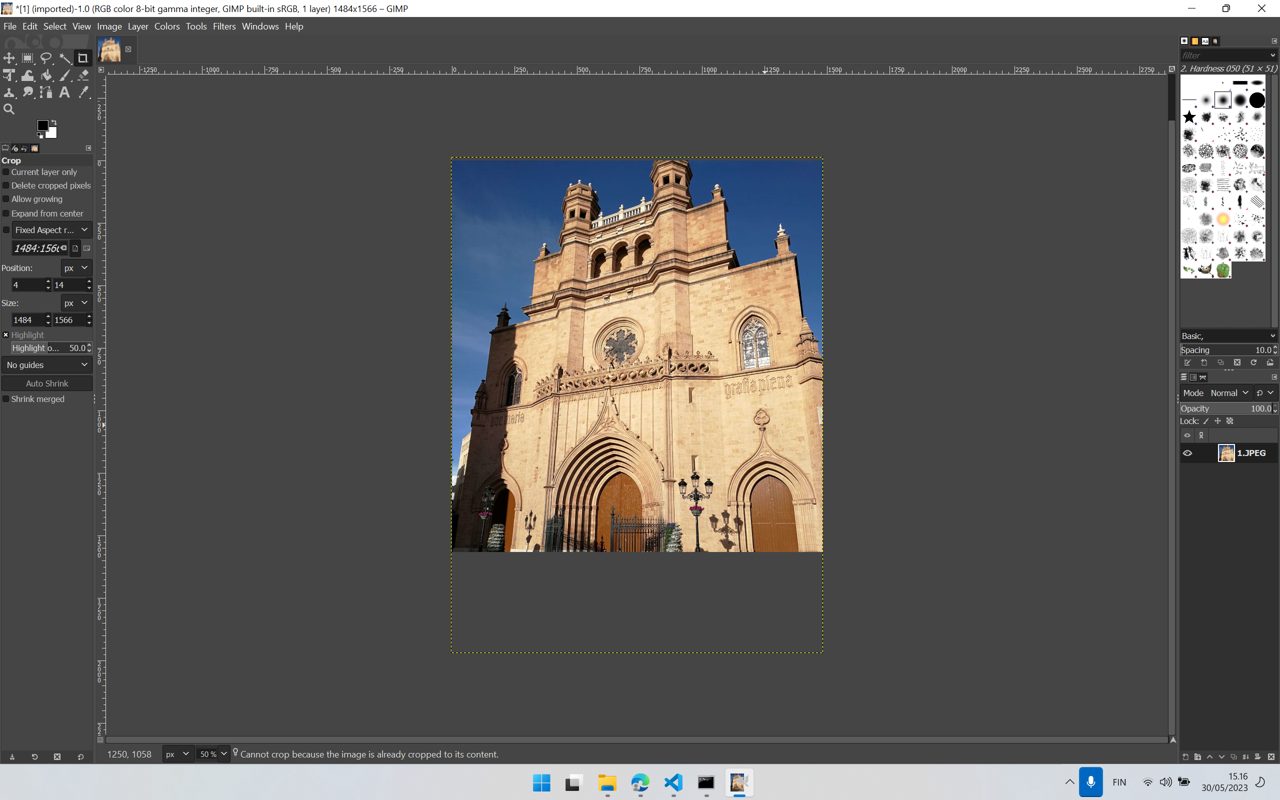 Figure 4: Cropped Final Image with no person in it: Click on the selected region for cropping to take effect.
GIMP file can be downloaded from here.
Augmenting a piece of new information in the cropped image
Next, I show how to augment new details to the existing image (Figure 4) in sequential steps (Figures 5-12). I chose to add textual information on the wall in the image.
 Figure 5: Click the Text Tool in the upper left corner, shown in the red circle.
 Figure 6: Click the region in the image where new information is to be augmented.
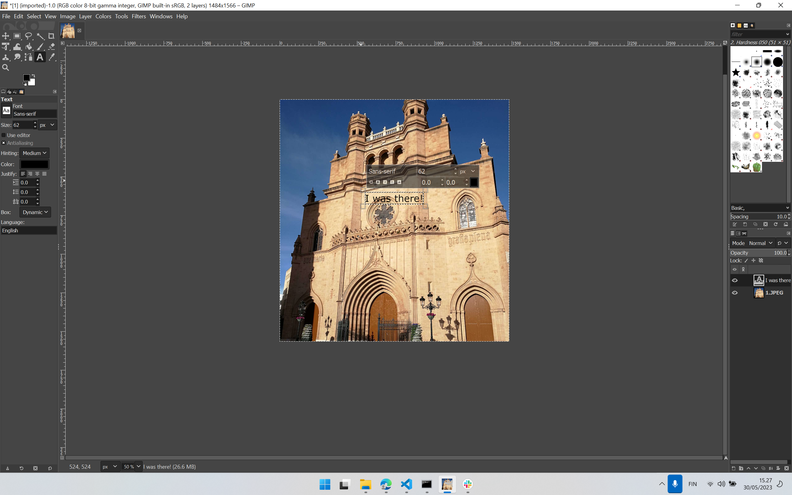 Figure 7: Write the information which needs to be augmented. I wrote “I was there!” as a sort of remembrance of my trip.
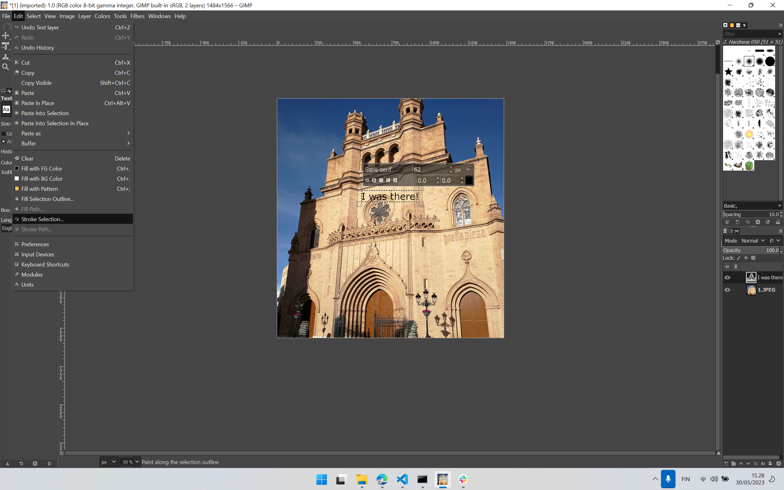 Figure 8: Selec Edit -> Stroke Selection… Click on this.
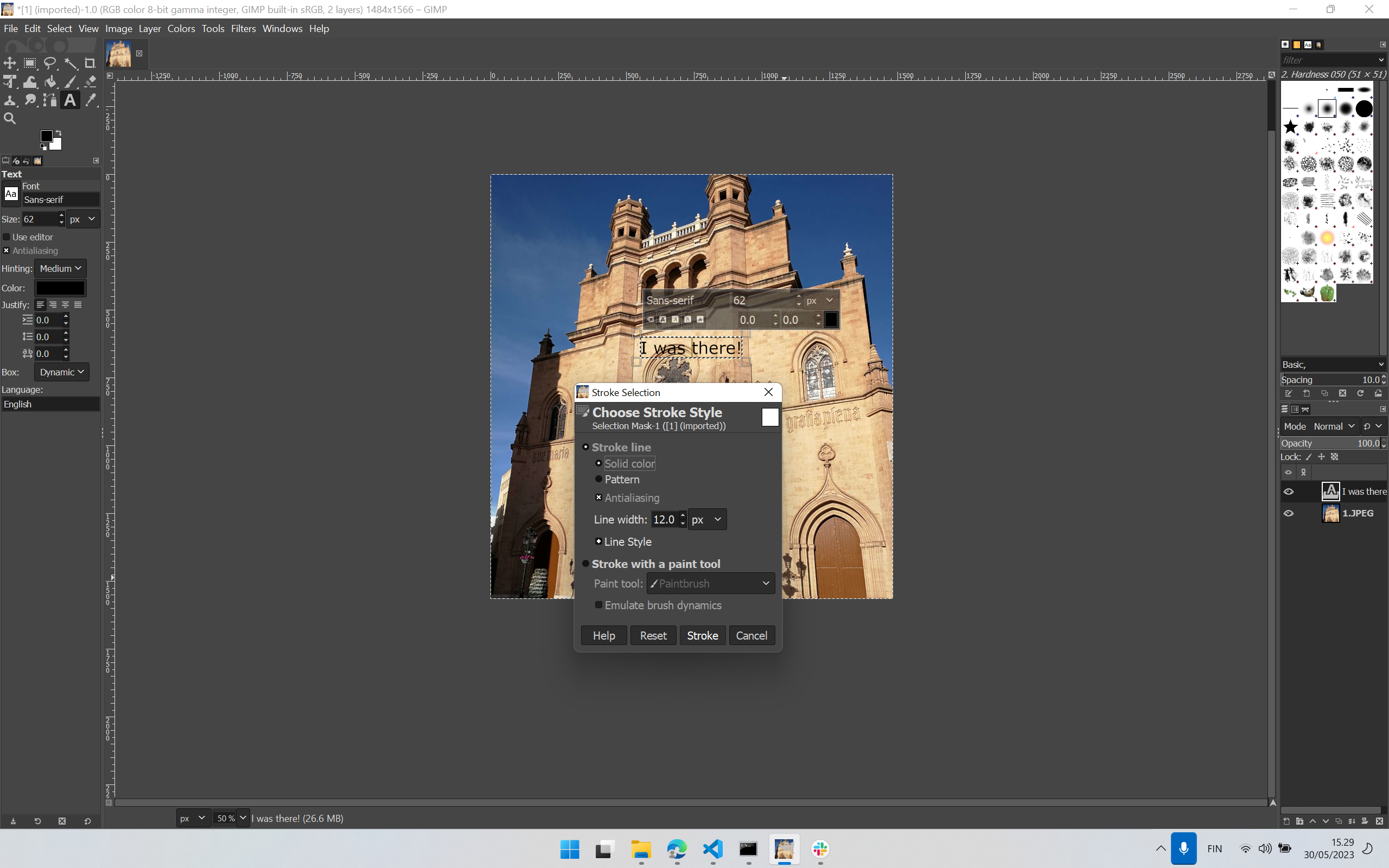 Figure 9: Edit parameters if needed in the shown dialogue box: Choose Stroke Style, and click Stroke.
 Figure 10: The text “I was there!” has been augmented to the image.
Now the image needs to be exported from GIMP.
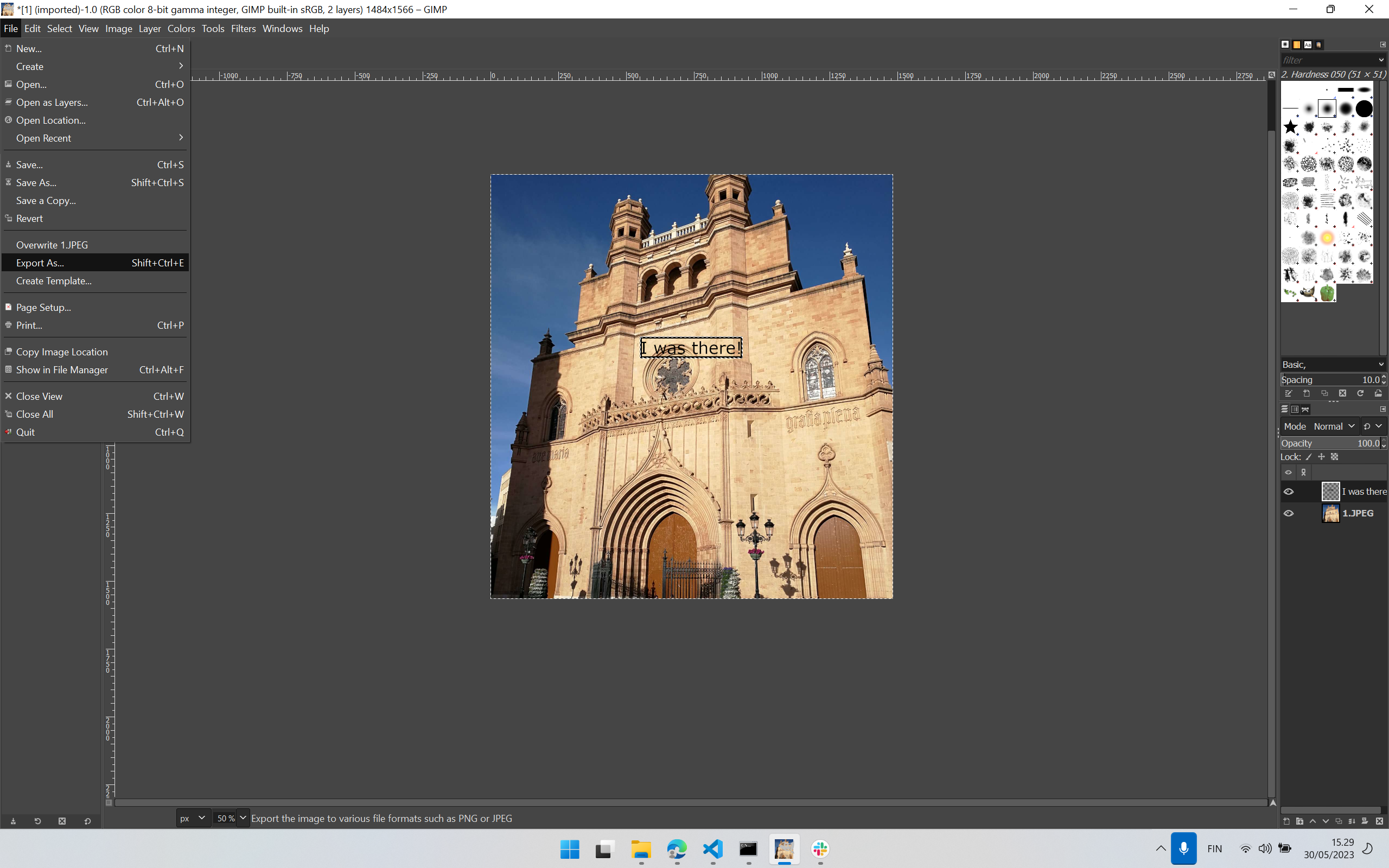 Figure 11: Steps: Select File -> Export As…
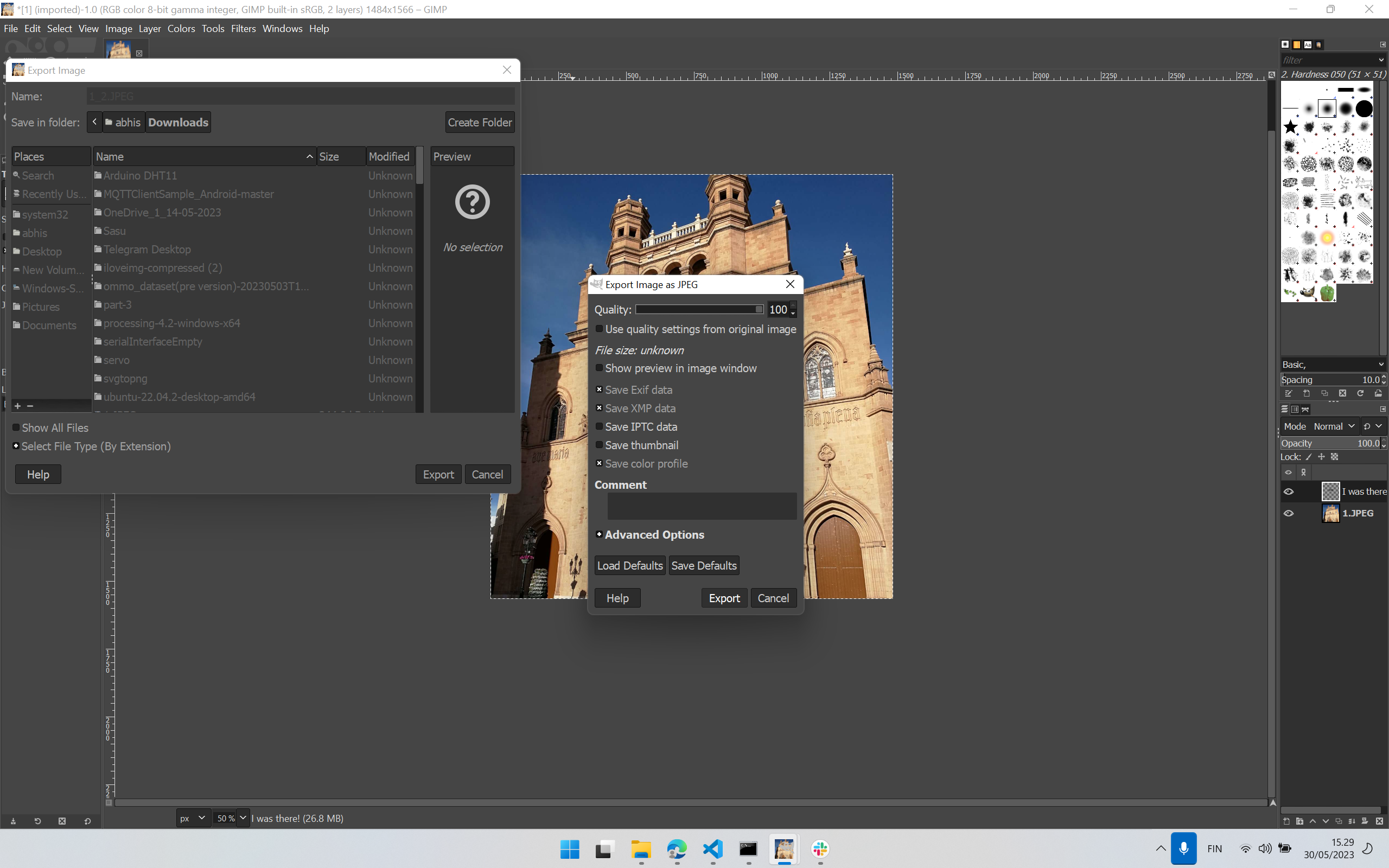 Figure 12: Select or edit parameters if needed in the new dialogue box: Export Image as JPEG, and click Export.
Augmented Image
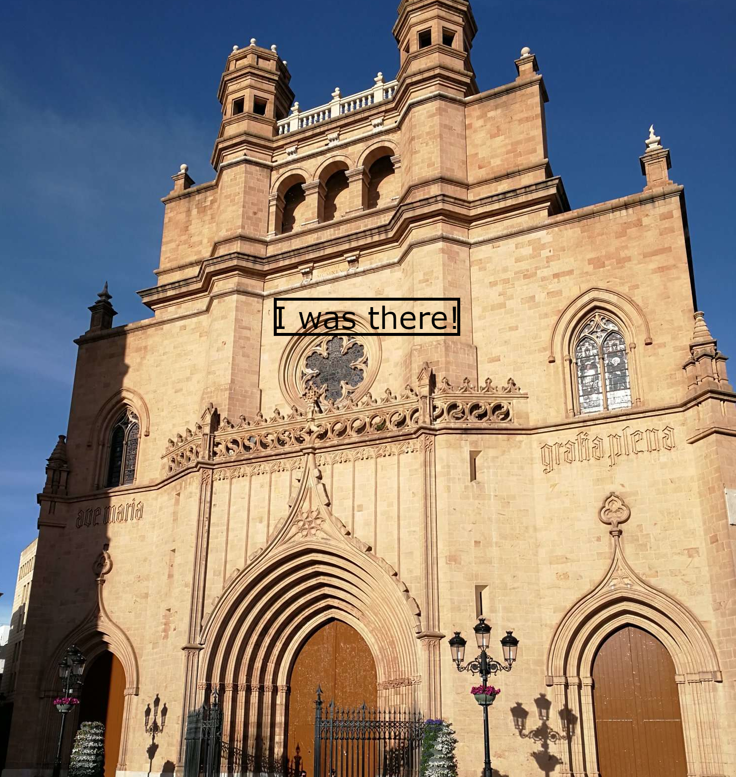 Figure 13: Final Image with augmented information.
GIMP file can be downloaded from here.
2D Design: Vector Image (with Inkscape)
In this part, I will create a text logo sticker for my final project. I plan to print this later using a Vinyl cutter machine and use it during the final project assembly. I will use it to demonstrate subtractive fabrication process and 2D design as required in the final project.
The text Logo is OPENAR since development in this project will be used in the ongoing OpenAR project at the University of Oulu and the University of Eastern Finland.
Next, I show steps in sequential order to make this in Inkscape. InkSpace, by design, creates 2D design.
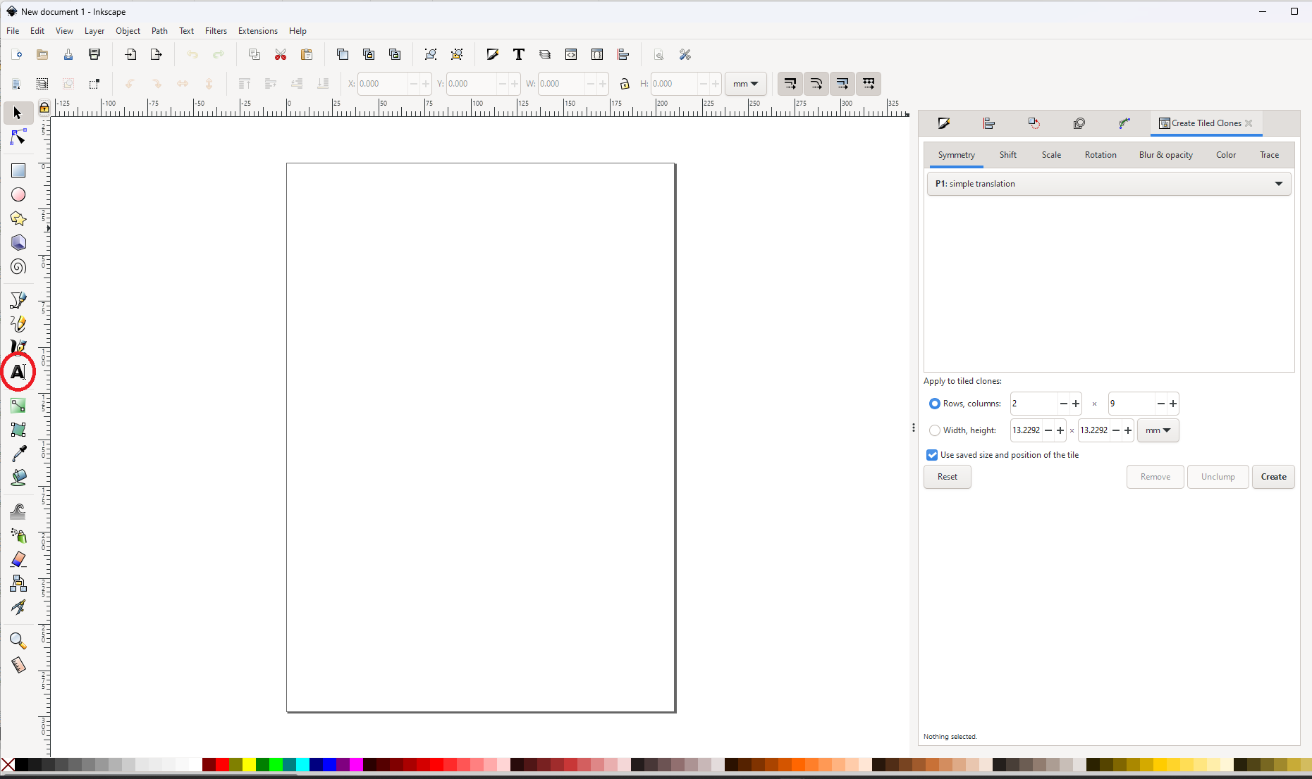 Figure 8: Select the Text tool by clicking the “A” symbol shown in the figure within the red circle.
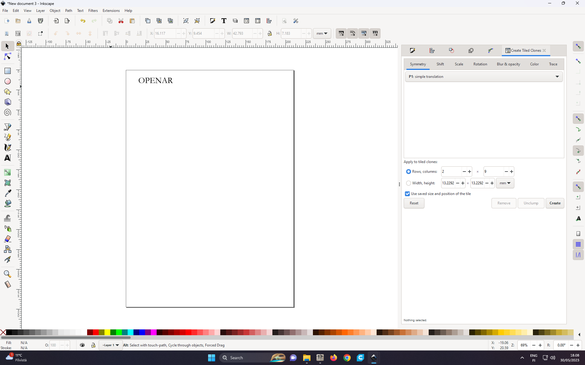 Figure 9: Next text for the logo is written: OPENER.
The plan is to pluck the letters from the background once it has been processed by the Vinyl cutter machine. So, we need to create a boundary for the logo.
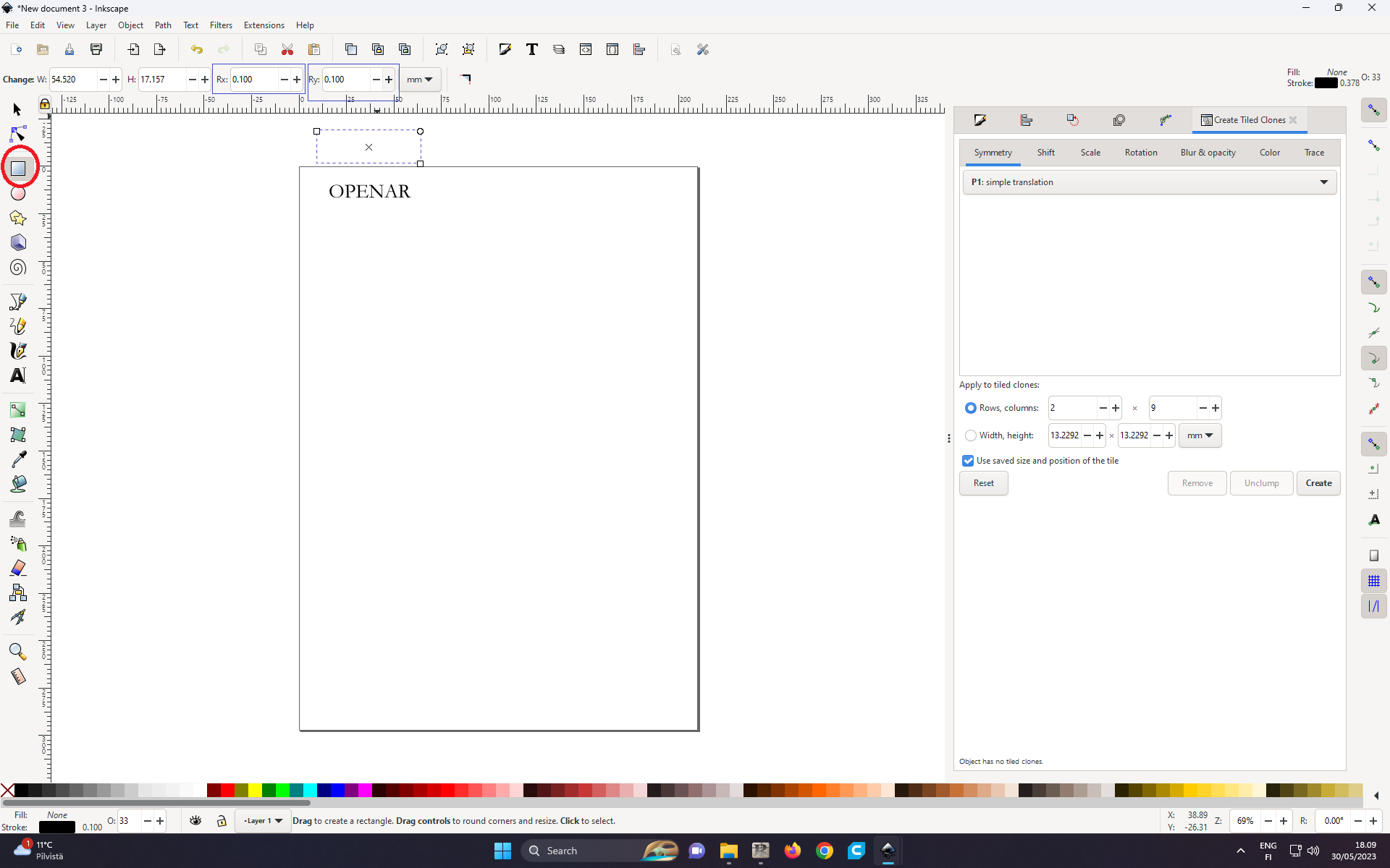 Figure 10: To create a boundary, select the rectangle shape in the left corner shown in the figure within the red circle. Set the thickness of the boundary by choosing parameters for Rx and Ry (shown in the blue coloured rectangle in the figure). Then move the rectangle boundary so that the logo text is within this boundary.
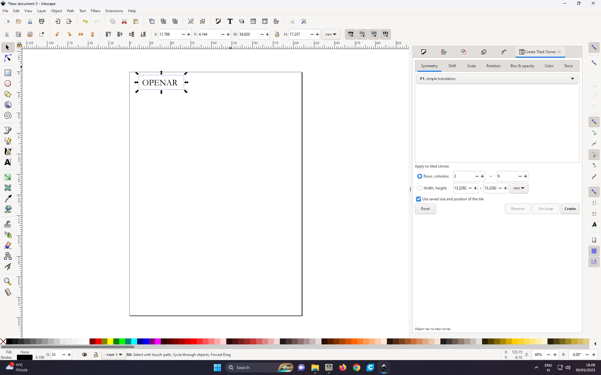 Figure 11: Logo text within the boundary
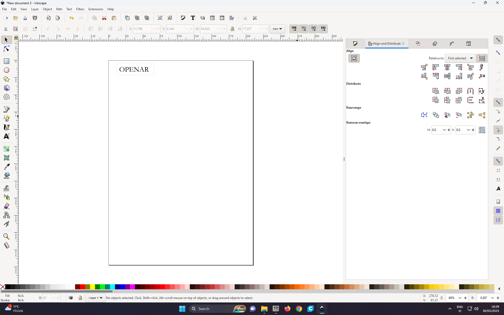 Figure 12: To align equally spaced from the upper and lower sides of the rectangle boundary, select Ctrl+Shift+A.
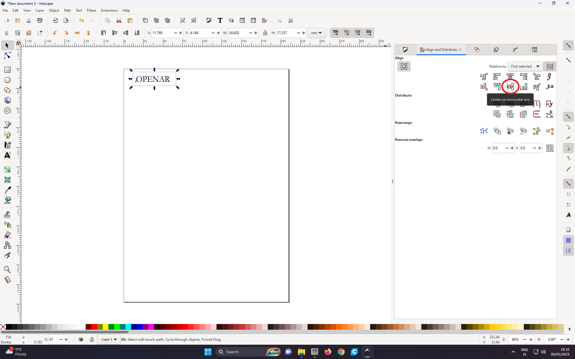 Figure 13: Select the icon shown in the red circle for equal alignment.
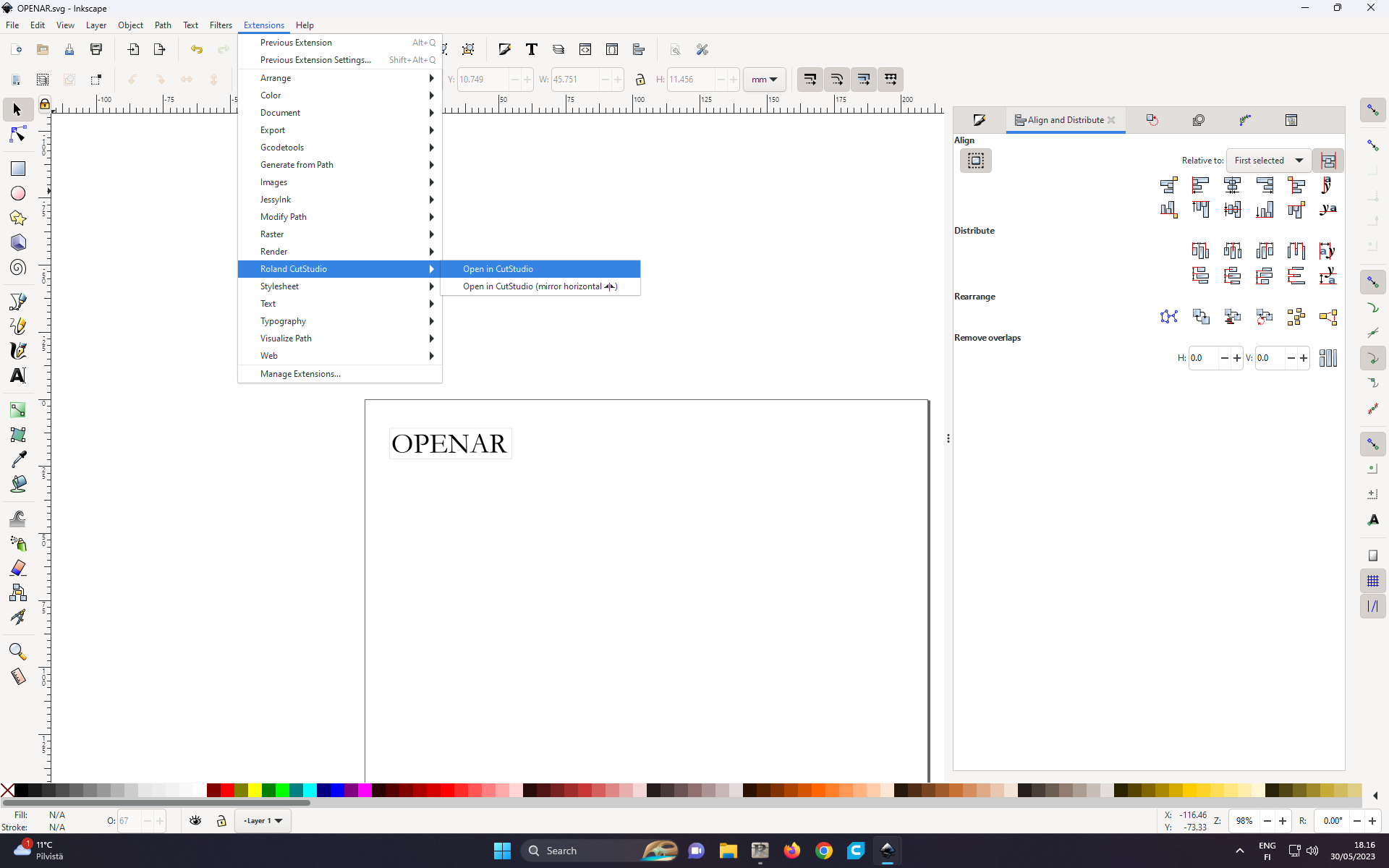 Figure 14: To begin the cutting, the vector image needs to be exported to the Roland CustStidio program. Select Extebsions -> Roland CutStudio -> Open in CustStudio.
Vector image (with text logo) can be downloaded from here.
Roland CutStudio file can be downloaded from here.
3D Design (with OpenSCAD)
For 3D design, I use OpenSCAD. Unlike FreeCAD, or Fushion 360, OpenSCAD is a 3D compiler that reads a script file that describes the object and renders the 3D model from the script file. Any 3D design which can be designed in graphical programs like FreeCAD, or Fushion 360 can also be designed in OpenSCAD. The only difference is that in OpenSCAD, the design needs to described in a a script (like writing a computer program).
For the 3D model, the idea was to build a similar “HOLLYWOOD” sign 3D strucutre as in Los Angeles.
 Figure 15: HollyWood Signpost in LA.
The following OpenSCAD simulates the signpost.
cylinder(r = 50, h = 8, center = true);
rotate([90,00,0])
linear_extrude(8) {
    translate([0, --4]) text("HOLLYWOOD", halign = "center");
}
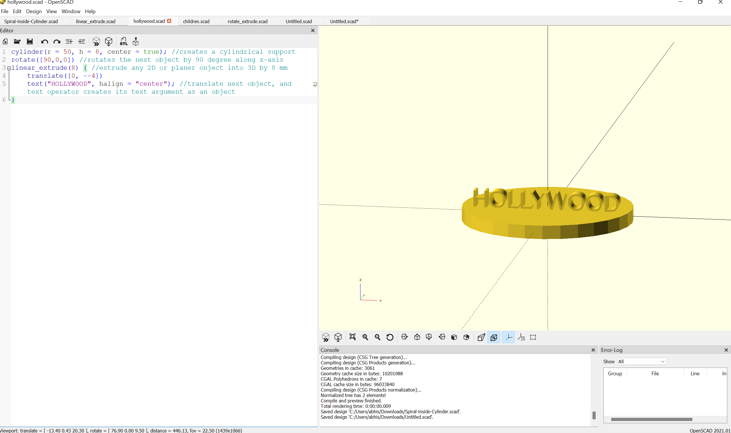 Figure 16: HollyWood Signpost in OpenSCAD.
OpenSCAD offers immediate preview mode to see how script is leading to a 3D design.
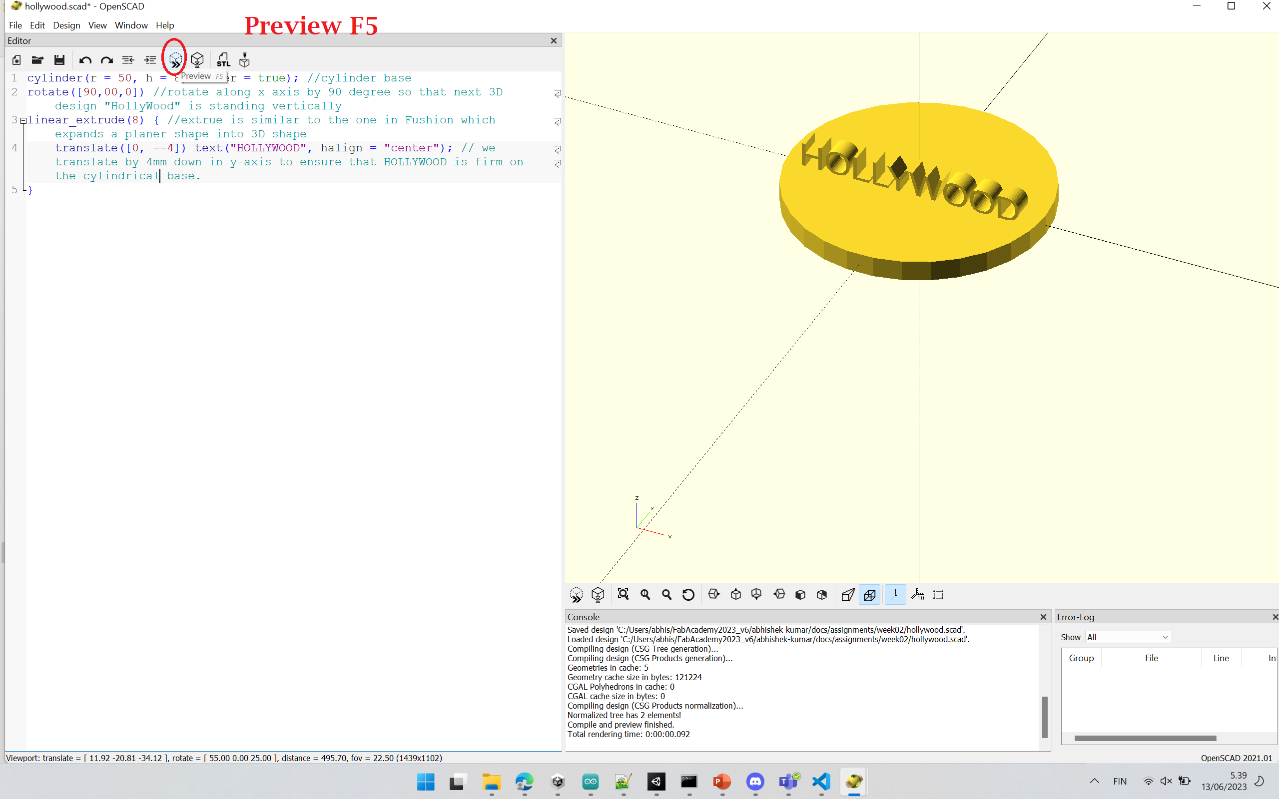 Figure 17: Previewing the current design in OpenSCAD. Shortcut Button for Preview: Press F5.
Once the script for the 3D design is finished, the Rendering option must be selected in order to generate an STL file because the rendering step generates the 3D mesh of the given 3D design. In other words no design can be exported before rendering step (since the 3D mesh is not ready yet).
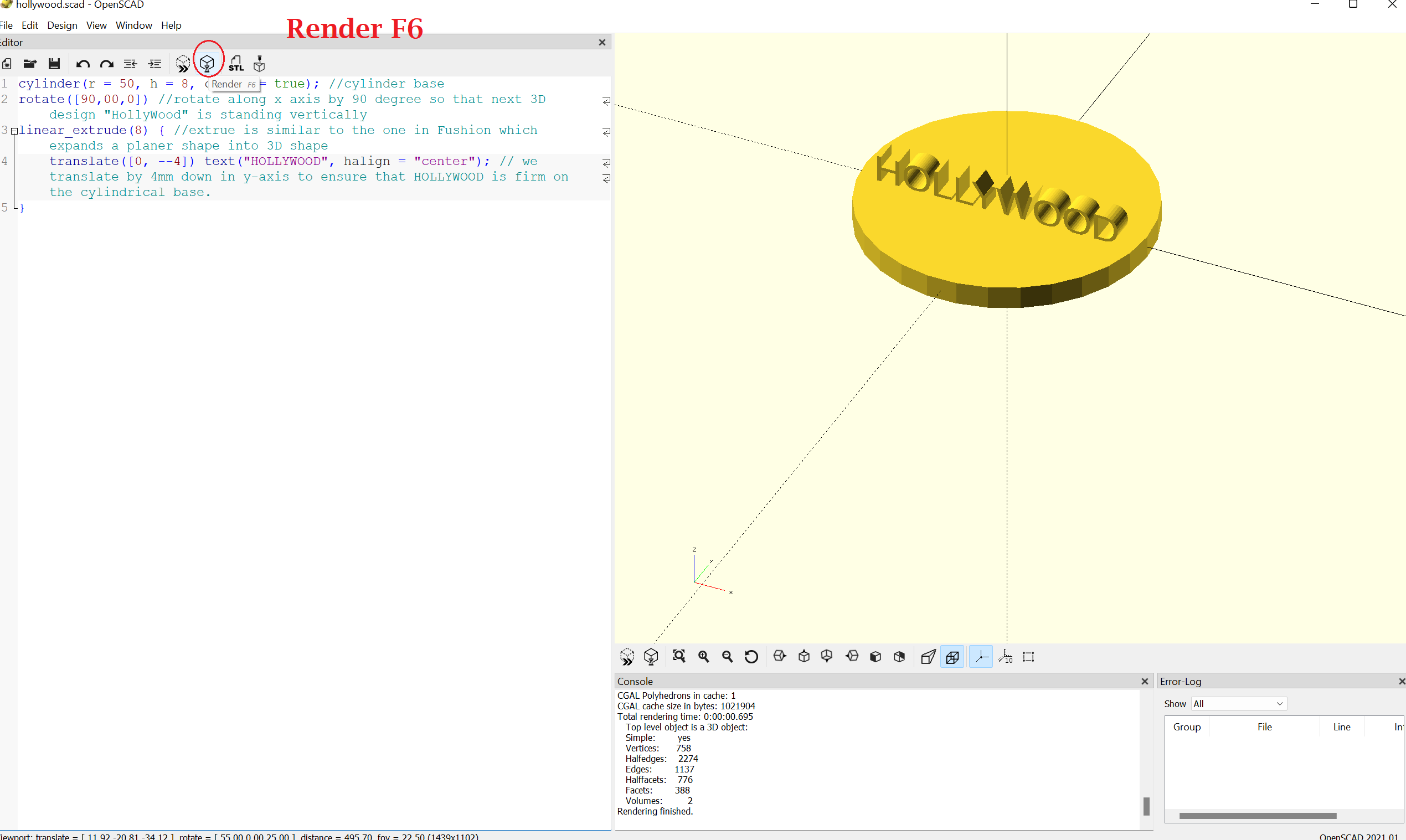 Figure 18: Rendering the finishes design in OpenSCAD. Shortcut Button for Render: Press F6.
Since rendering was performed previously, 3D mesh of the design has been generated. Now it can be exported as an STL file.
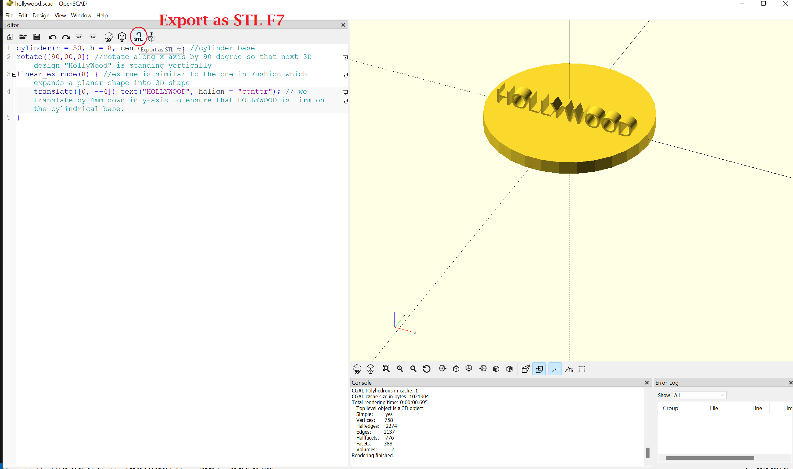 Figure 19: Exporting the finished design in OpenSCAD as an STL file. Shortcut Button for exporting STL file: Press F7.
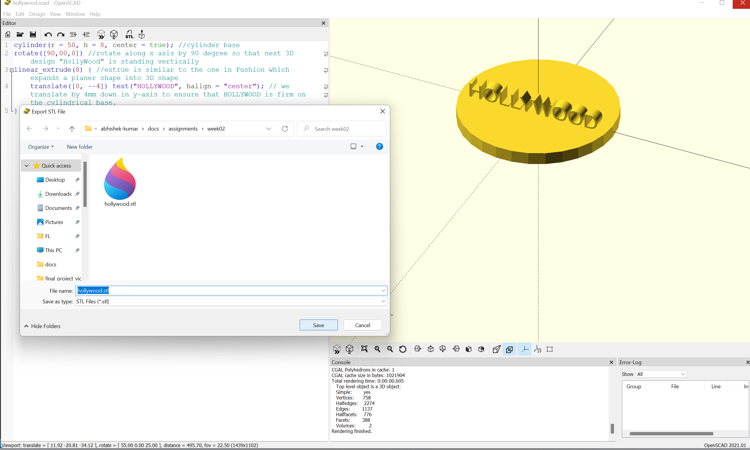 Figure 20: Saving exported STL file from OpenSCAD into the local computer.
OpenSCAD script with comments can be found here.
STL file can be found here.
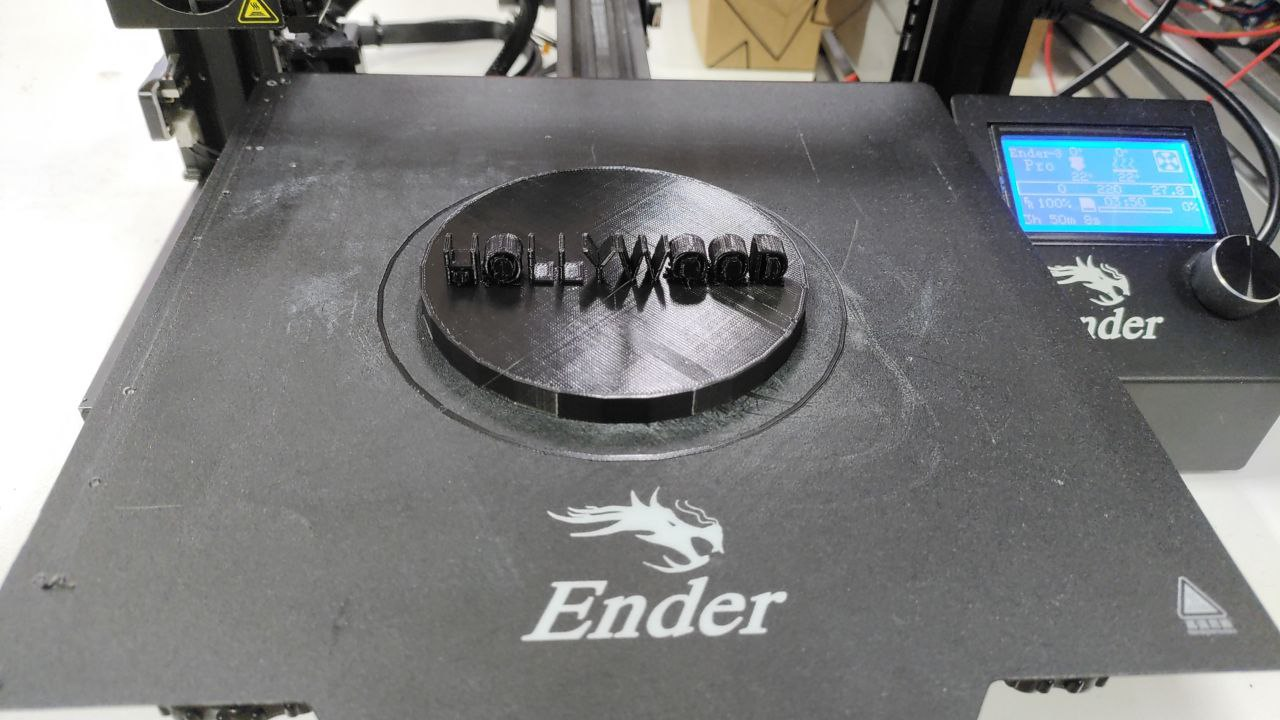 Figure 21: 3D Printed Structure.
Equivalence of OpenSCAD with Graphical tools like Fusion 360, or FreeCAD.
-
Line 1 in OpenSCAD code: Making a cylinder with a height of 8 mm and radius of 40mm, and centre at (0,0,0). OpenSCAD offers a command cylinder(). FreeCAD/Fusion 360 also offers cylinder objects.
-
Line 2 in OpenSCAD code: We want to have the next 3D structure standing on the cylindrical base we created in Line. For that, OpenSCAD offers a method called rotate([X, Y, Z]). Giving such a command will rotate the next immediate 3D object along the x-axis by X degrees, along the y-axis by Y degrees, and along the x-axis by Z degrees. In my code, the next 3D object is rotated along the x-axis by 90 degrees and is not rotated along the y-axis and z-axis. This command ensures that the next 3D object will be standing on the cylinder we created in line 1.
In FreeCAD or Fusion 360, we first create the 3D object, and we manually rotate it, whereas, in OpenSCAD, we need to give rotate command first for the next 3D object to rotate (i.e. before creating the 3D object).
- Lines 3-6 in OpenSCAD code: It creates the 3D object in the shape of “HOLLYWOOD.” It is made in 2 steps. – Step 1: We create “HOLLYWOOD” in a 2D plane, by simply typing each of the characters of the word (aka. 2D object at this stage). – Step 2: We select the 2D object, and extrude it by 8 mm to make it a 3D object. In OpenSCAD, it is done by the command linear_extrude(). In FreeCAD or OpenSCAD, we just need to select the 2D object, click on extrude button (built-in option) and specify how much to extrude.
Compressing images and videos
Compressing Images
I use Gimp to compress images. Any image to be compressed can be loaded in Gimp, just like done with an image I took during Spain trip to the Gimp (shown in Figure 1). Then, we try to export the image from Gimp, just like shown in Figure 11. Figure 12 (next step) shows a new dialogue box which has a number of edit paramaters. To compress the image, we will need to reduce the value of “Quality” paramater (shown in Figure 12), let say from 100 to 80, depending on how much size reduction we require.
Compressing Video
Video compression (fixed bit rate encoding)
I use the following HTML5 MP4 ffmpeg encoding command for compressing videos.
ffmpeg -i input_video.mp4 -vcodec libx264 -b:v 1000k -vf scale=-2:1080 -acodec mp2 -b:a 256k -ar 48000 -ac 2 output_video.mp4
Windows operating system have usually ffmpeg command support already available. input_video.mp4 is the name of the video file we want to compress. output_video.mp4 will be the resulting compressed video file. To lower the size, we would need to change the field between “…libx264 -b:v” and “-vf scale=-2:1080 …” to furthur down, let say from 1000k to 800k depending on how much size reduction we require.
The above mentioned command ensures fixed bit rate which is great in a stable network conditions, or for small files. In a unstable or nosy networking conditions, varaible bit rate coding might be preferred. So far, my files have been very small, i.e. in the order of less than 100 MB. So, it has not created any major issue. But with big files, let say 200 MB plus, I might need to consider using a command which performes variable bit rate encoding.
Video compression (no audio)
I use the following HTML5 MP4 ffmpeg encoding command for compressing videos wherein I want to get rid of any audio present in the video at all.
ffmpeg -i input_video.mp4 -vcodec libx264 -b:v 1000k -vf scale=-2:1080 -an output_video.mp4
Sometimes getting rid of audio may itself reduce the size of the video file to extent that it fullfills out requirement. If it still does not, then we can compress by reducing the field between “…libx264 -b:v” and “-vf scale=-2:1080 …” as stated previously.
More options of compressing videos can be found here.