5. 3D Scanning and printing
This week I worked on getting my hands on four different 3D Printers: 1) Raise 3D Pro2, 2) Enders, 3) FormLabs, and 4) Fortus 380 during the group work. Then, I worked with MakerBot Digitizer 3D Scanner.
Reflection on 3D printing group work
I gathered the following insights and observations from our group work:
1) Fortus 380 mc’s test prints had multiple spaghetti types of structure. I would not use this for fine-grained printing. It was unexpected a bit because Fortus 380 mc is supposed to be an industrial-grade 3D printer.
2) Form Labs’ printing takes a long amount of time because of post-processing processes.
3) Raise 3D pro2 had some spaghetti types of structures.
4) All printers printed diameters accurately. There was a slight deviation in the printed object from the design with Ender (7.5 mm versus 8.0 mm design and 6.5 mm versus 6.0 mm design).
Overall, I would not choose Fortus 380 mc and Form Labs but rather go with Ender for 3D printing any object for my projects for the first choice. The second choice would be Raise 3D.
3D Scanning
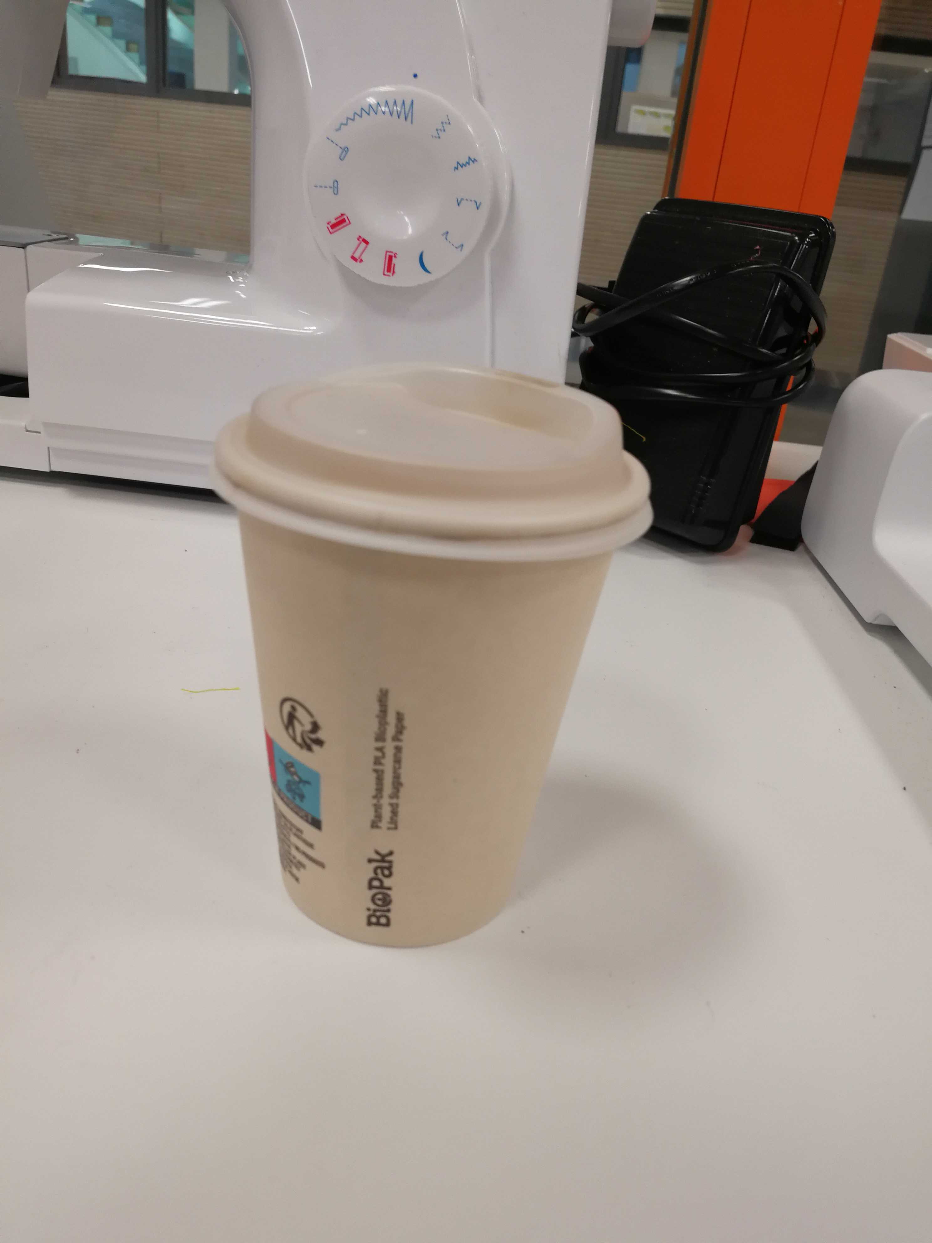
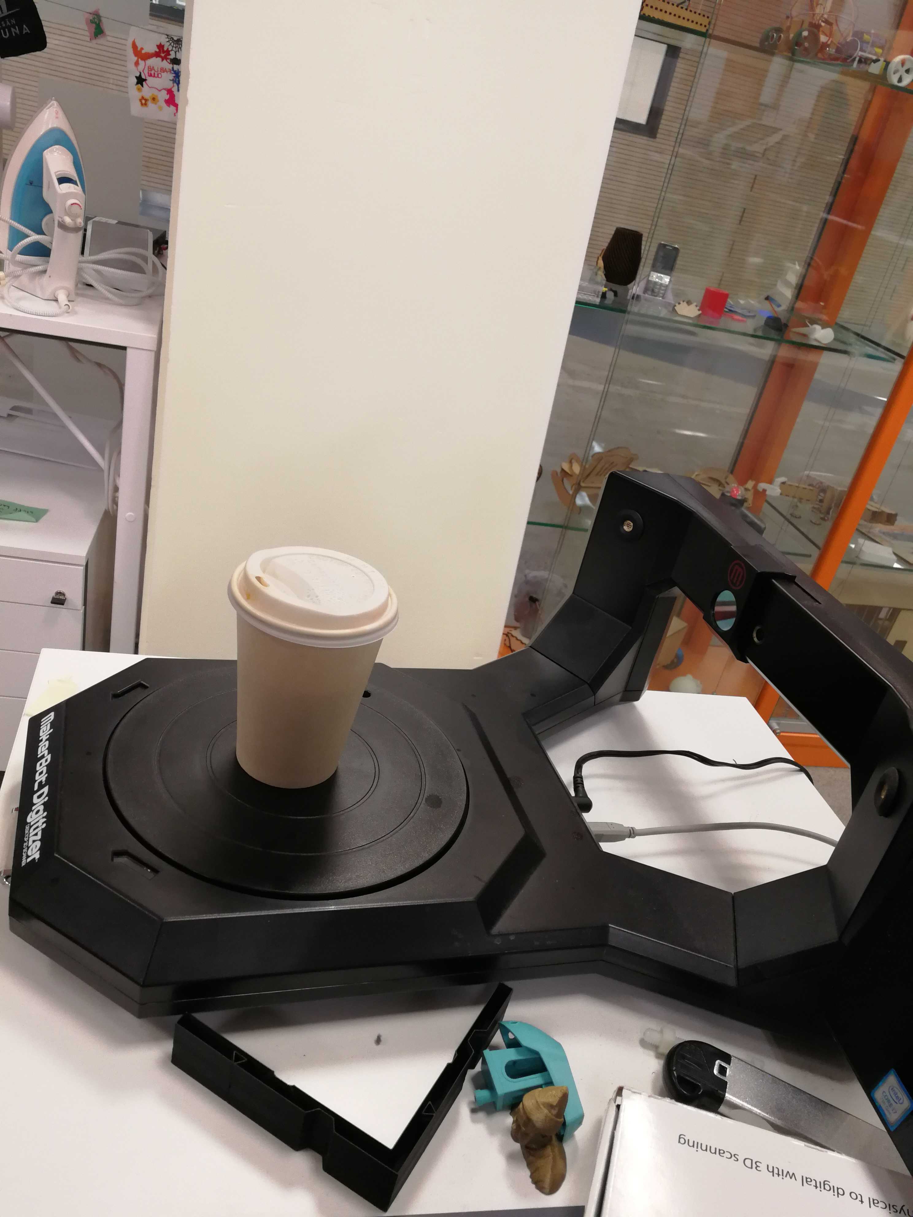
The original 3D object was Coffee Glass as follows:
(1) The filter (in yellow circle) needs to be over the Camera lens (in red circle) of MakerBot Digitizer as shown in Figure 2. If not, it needs to be adjusted as such. There should be no bright light coming (like sunlight, light coming from the Window) out from external sources in line of the camera.
(2) Next step is calibration which requires placing the checkerboard calibration tool in the centre of the turntable in three different orientations (A-side up, B-side up, C-side up). The turntable spins around scanning the calibration device in each of these three orientations, and this entire process takes about 10-15 minutes. Instructions were given on the computer, and the calibration process was relatively straightforward.
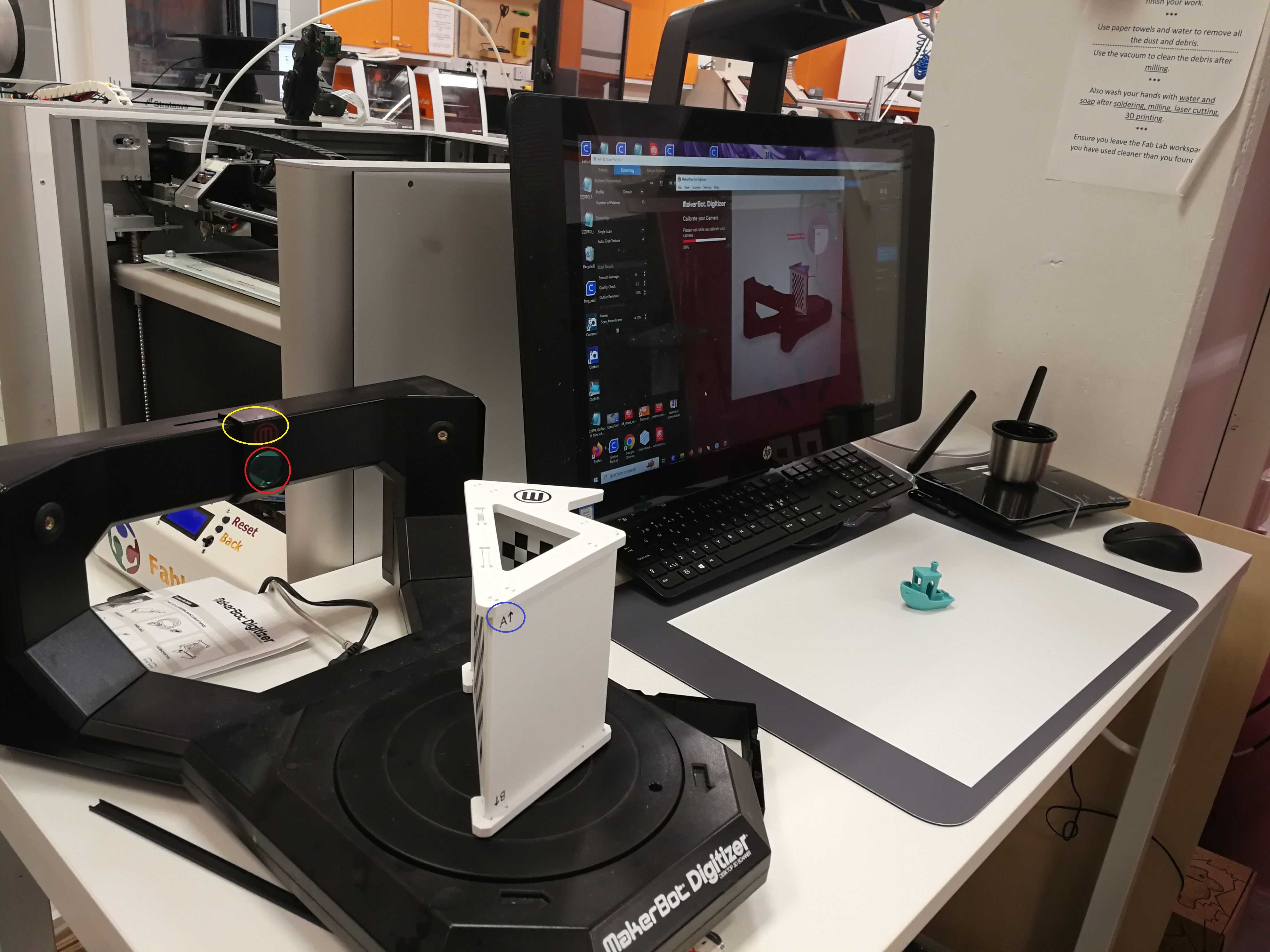 Figure 2. Snapshot of Digitizer’s calibration process in A-side up orientation.
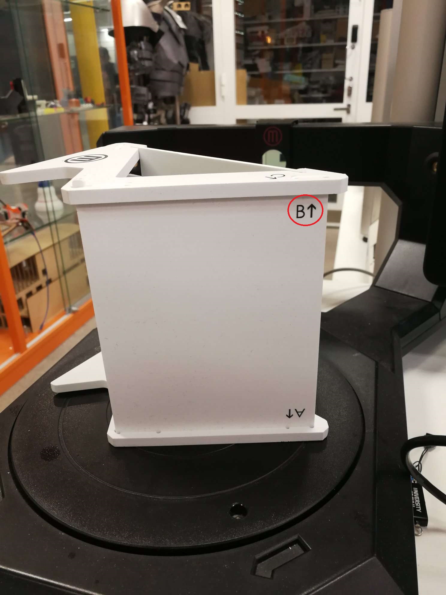 Figure 3: Snapshot of Digitizer’s calibration process in B-side up orientation.
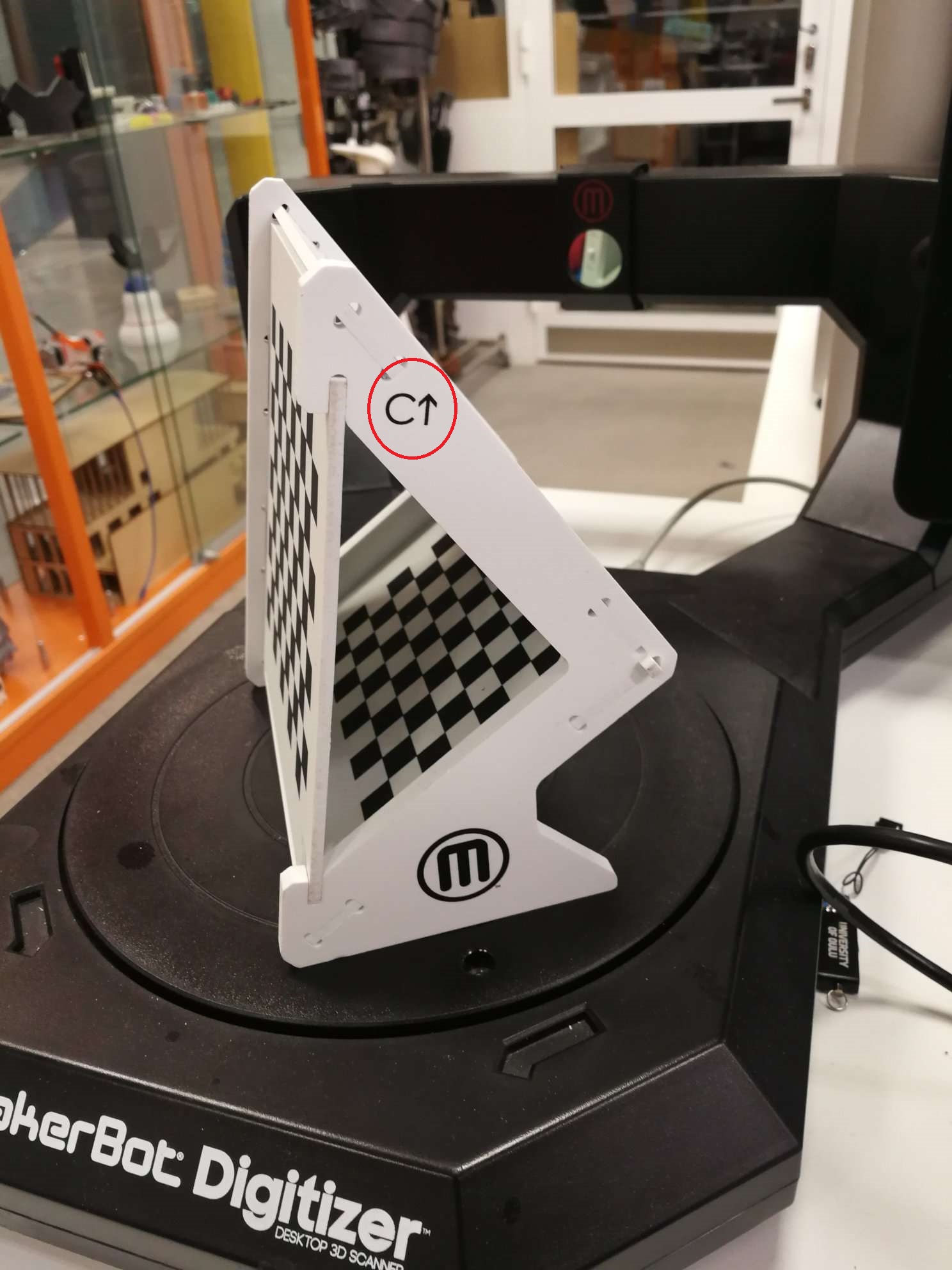 Figure 4: Snapshot of Digitizer’s calibration process in C-side up orientation.
(3) Next step is choosing a preset setting based on the shade of the object to be scanned among these three options: light, Medium, and Dark. The “Light” option should be used when scanning lighter-coloured objects. The “Medium” option should be used when scanning objects which are neither light nor dark. The “Dark” option should be used when scanning objects that are difficult to scan, such as dark, shiny or fuzzy objects. I chose the “light” option. Then, Click the “Done” option because my object “Coffee Glass” had quite a light shade.
(4) After the calibration process and choosing the shade, Coffee Glass was left on Digitizer for 10 minutes. Digitizer showed expectation time to finish scanning was 8 minutes in the beginning. After 10 min, it was ready, and I exported the STL file.
Demo Video
The following 10-second video clip shows a 3D Scan of the Coffee Glass.
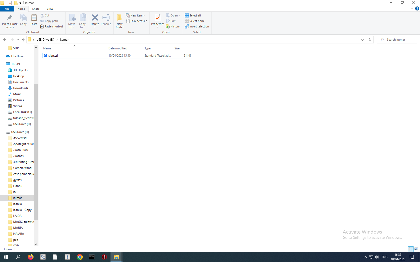
The STL file of the 3D Scan of Coffee Glass can be found here.
3D printing
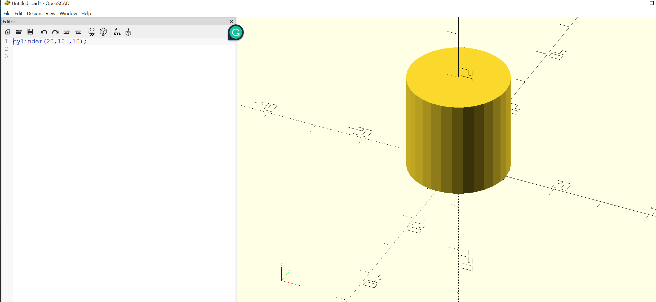
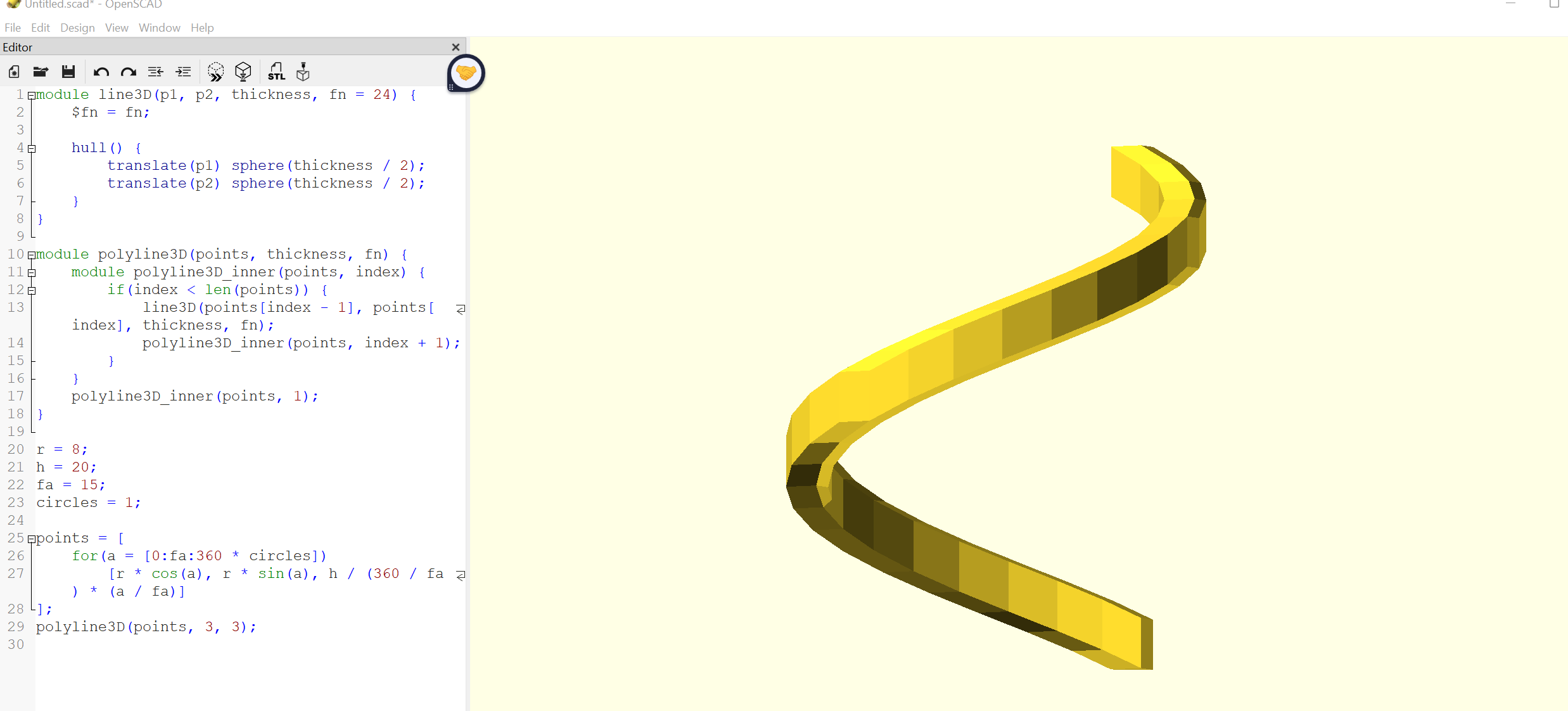
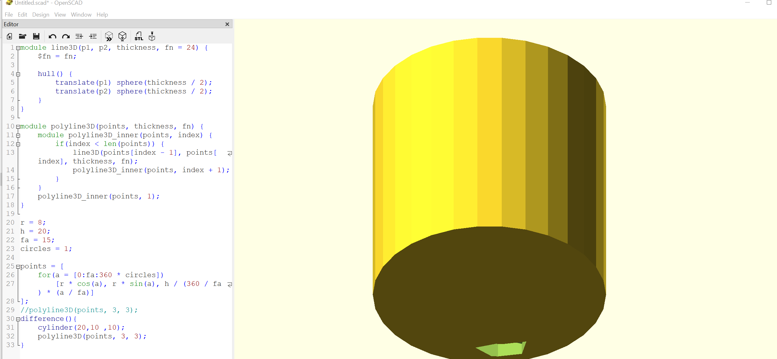
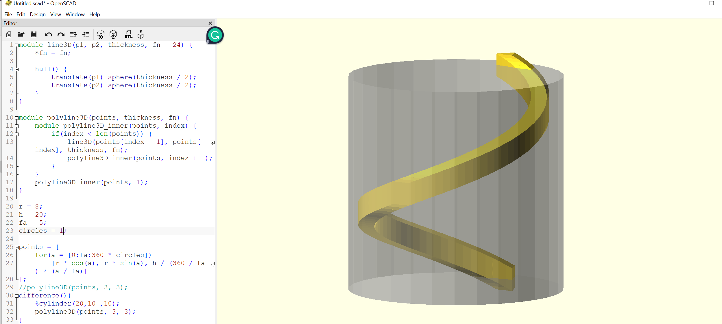
For the 3D printing, we needed to print something that cannot be created subtractively. I chose to create a cylinder (in Figure 7) with a spiral (in Figure 8) hollow inside from top to bottom.
Code
The following code is in OpenSCAD. Unlike FreeCAD, or Fushion 360, OpenSCAD is a 3D compiler that reads a script file that describes the object and renders the 3D model from the script file.
For creating a spiral pattern, I used codes from this site.
//this module creates a 3D line. Essentially it is an elongated 3D polygon
module line3D(p1, p2, thickness, fn = 24) {
$fn = fn;
//hull is a 3D transformation in OpenSCAD which combines multiple modules into one nice cover. https://en.wikibooks.org/wiki/OpenSCAD_User_Manual/Transformations#hull
hull() {
translate(p1) sphere(thickness / 2);
translate(p2) sphere(thickness / 2);
}
}
//this module utilizes 3D line iterative to generate a locus of 3D lines which accumulatively gives the resemblance of a 3D Spiral.
module polyline3D(points, thickness, fn) {
module polyline3D_inner(points, index) {
if(index < len(points)) {
line3D(points[index - 1], points[index], thickness, fn);
polyline3D_inner(points, index + 1);
}
}
polyline3D_inner(points, 1);
}
//Spiral parameters, i.e. thickness, radius, how many layers
r = 8;
h = 20;
fa = 15;
circles = 1;
//locus of points which are used in Hull transformation to create a 3D line using the line3D module mentioned above
points = [
for(a = [0:fa:360 * circles])
[r * cos(a), r * sin(a), h / (360 / fa) * (a / fa)]
];
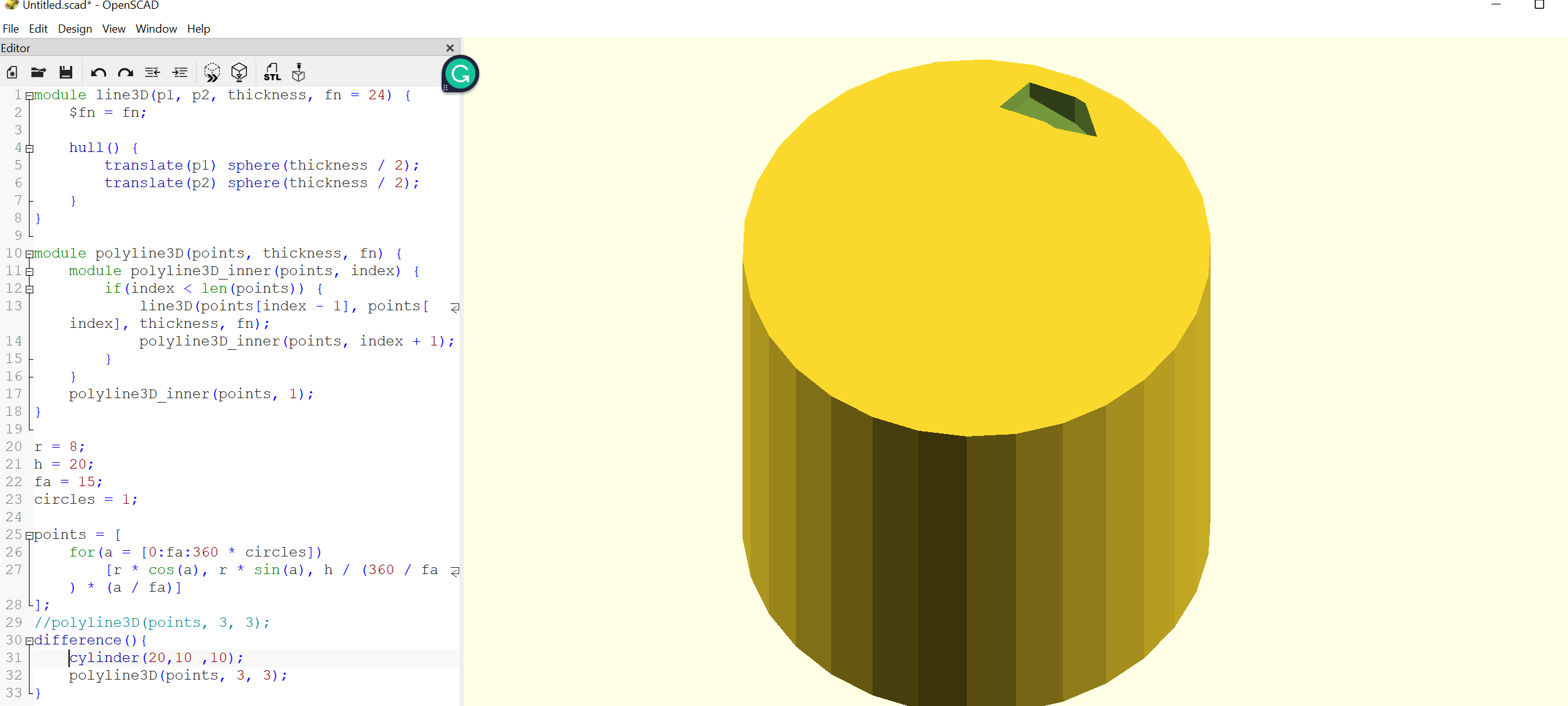
difference(){//subtracting spiral from a cylinder using difference operator
cylinder(20,10 ,10); //Solid sylinder
polyline3D(points, 3, 3); // 3D spiral
}
The OpenSCAD file can be found here.
The STL file can be found here.
Printing with Ender 3D Printer
Pre-processing of STL file with Ultimaker Program
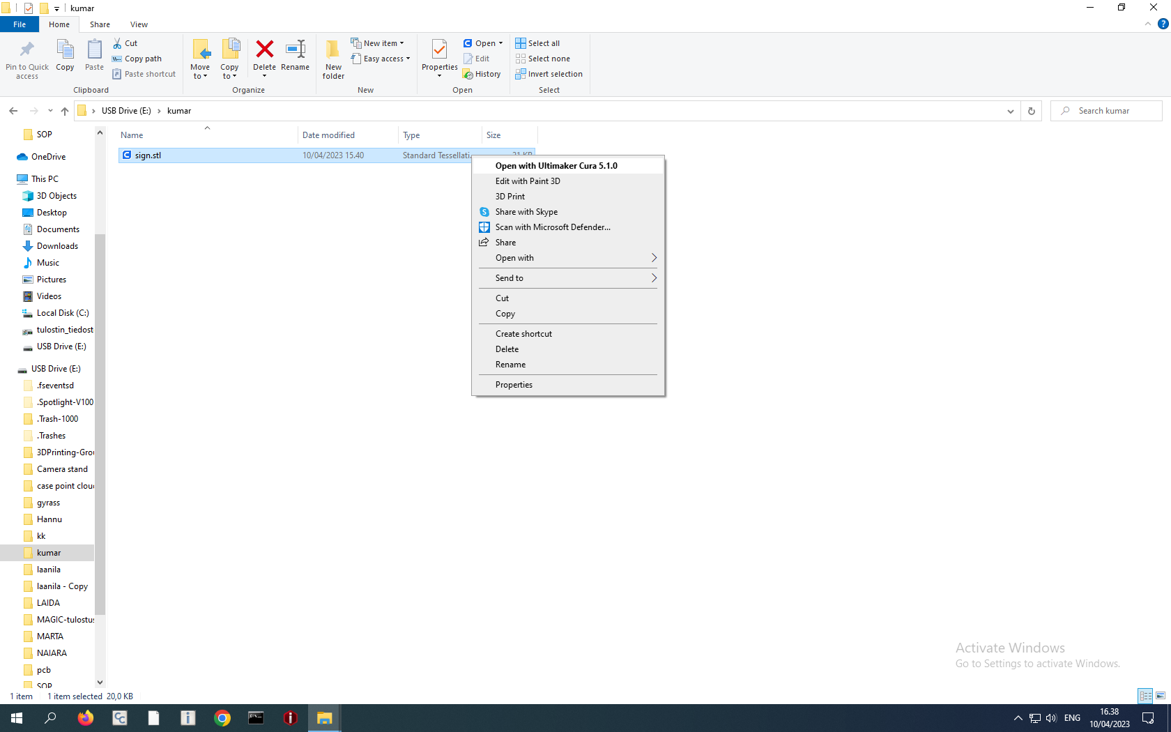
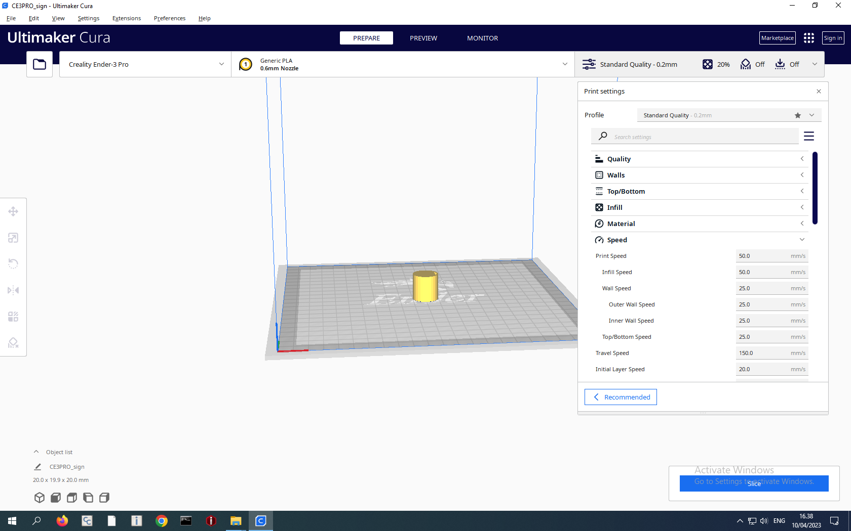
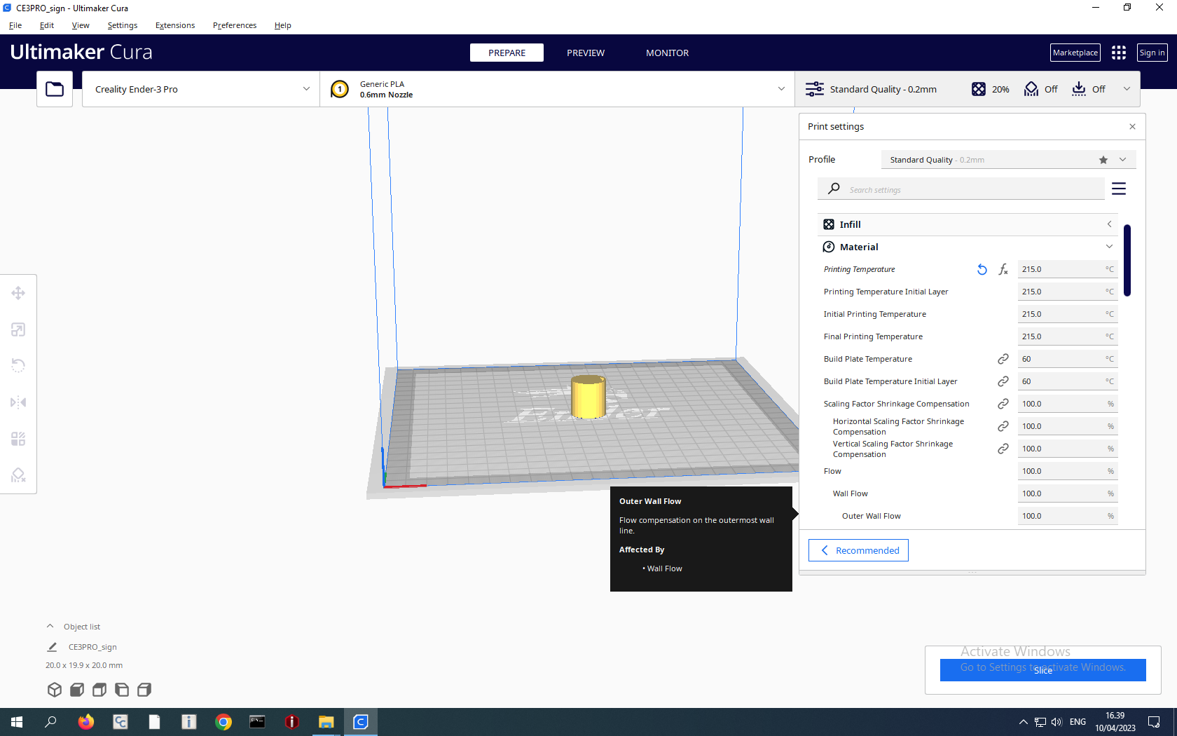
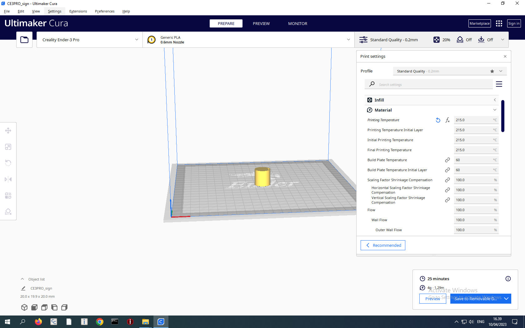
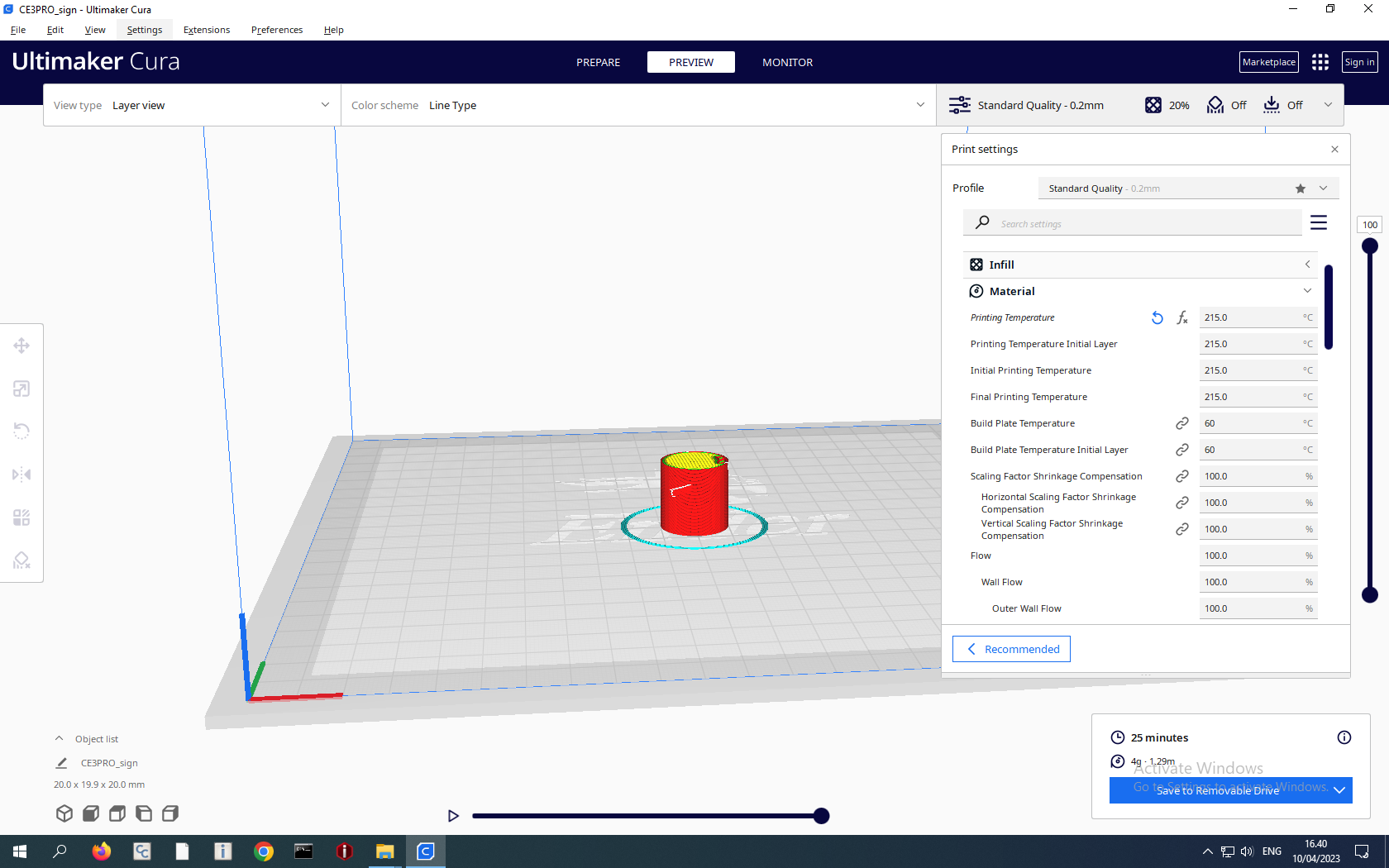
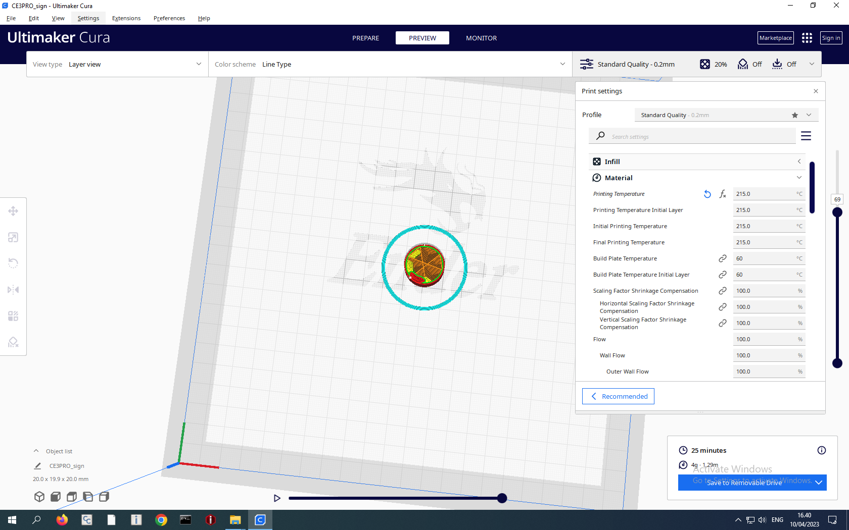
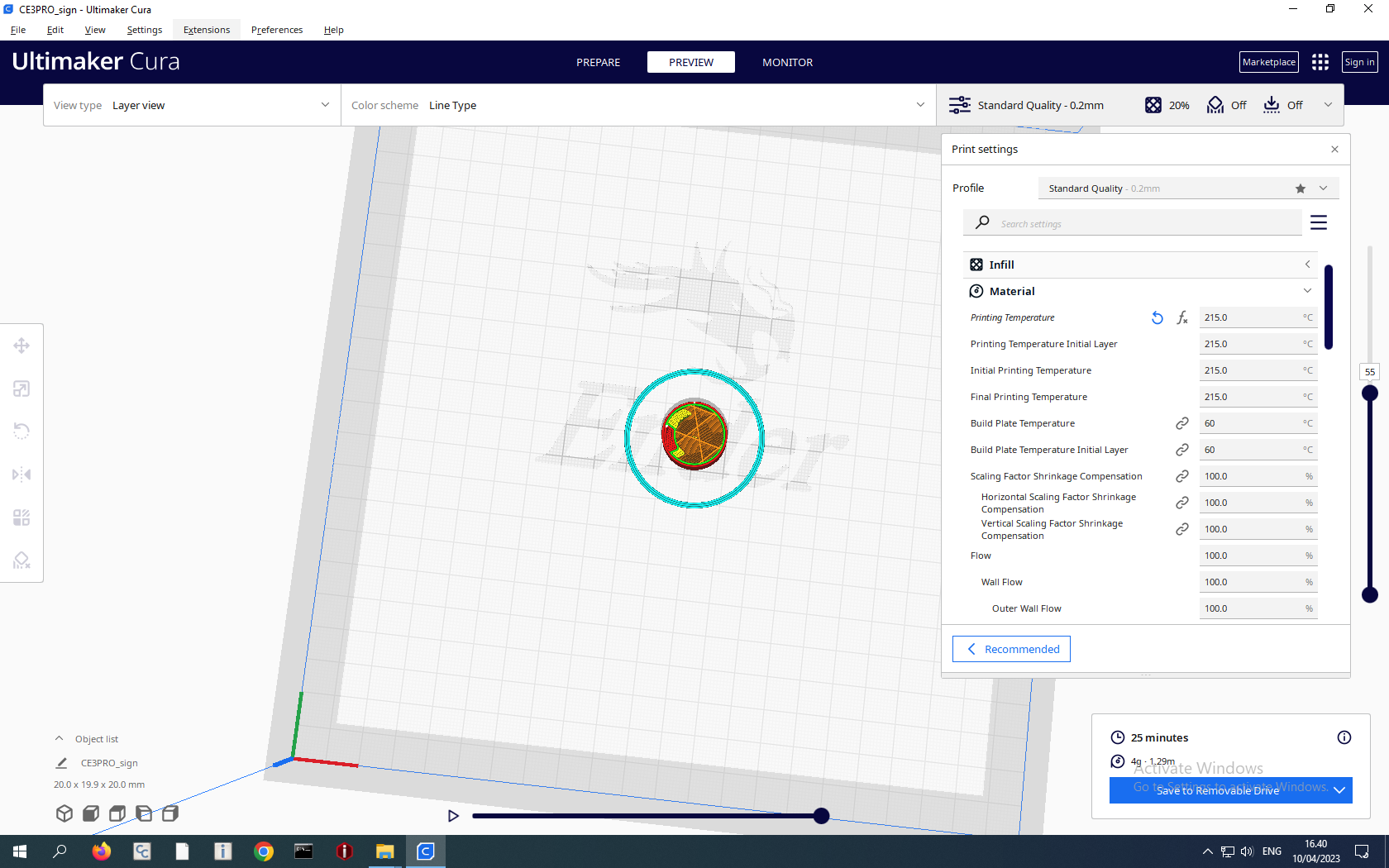
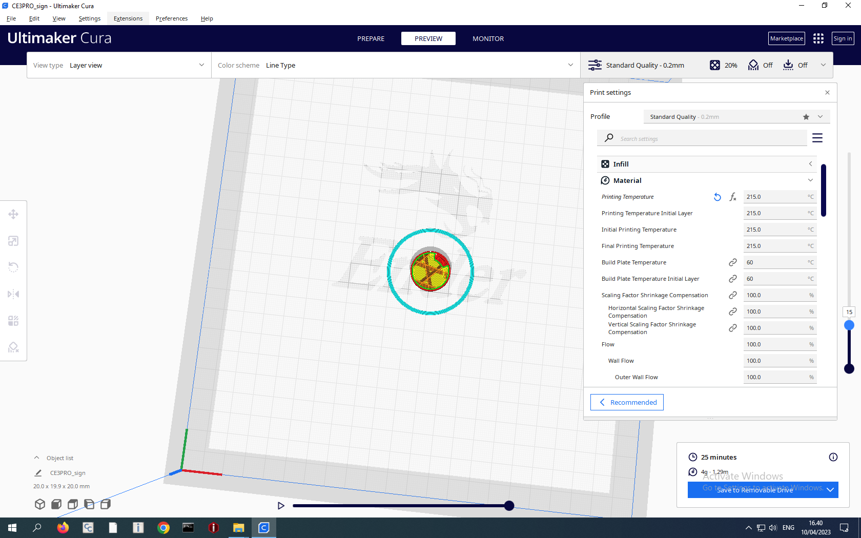
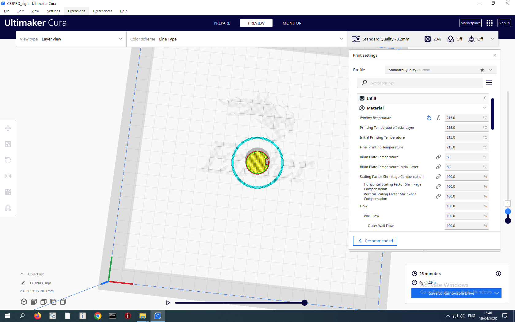
The processing of the STL file with the Ultimaker program generates a gscode file, which needs to be transferred to the 3D printer by clicking on the “Save to Removable Drive” option at the bottom left corner in Figure 22. The 3D printer I used was not connected to the computer via a wireless network, so I needed to move the gscode file to the printer via a memory card stick.
Why my chosen 3D design can not be created via subtractive fabrication via tools like a CNC machine?
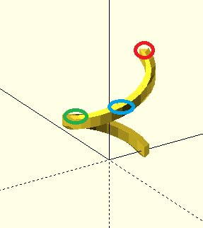
Figure 23: Spiral patterned Hollow Region inside the Solid Cylinder.
Figure 23 shows a spiral pattern which is hollowed from the solid cylinder. The needle of a subtractive fabrication tool like a CNC machine can hollow out components from the top (shown in red circle), but the needle can not reach out to hollow out components from blue and green regions of the spiral, because the region above and below them are solid filed. CNC needles move only in linear directions while hollowing out spiral patterns require non-linear movements.
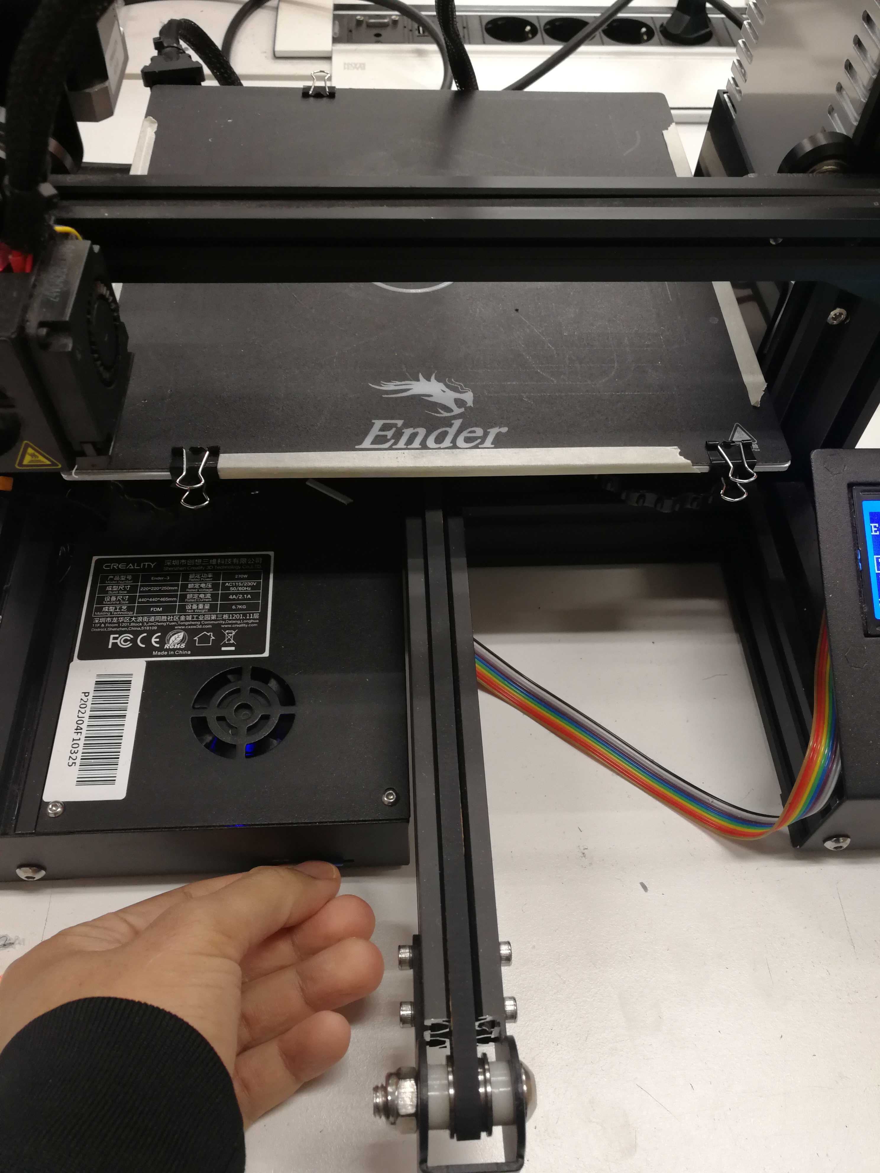
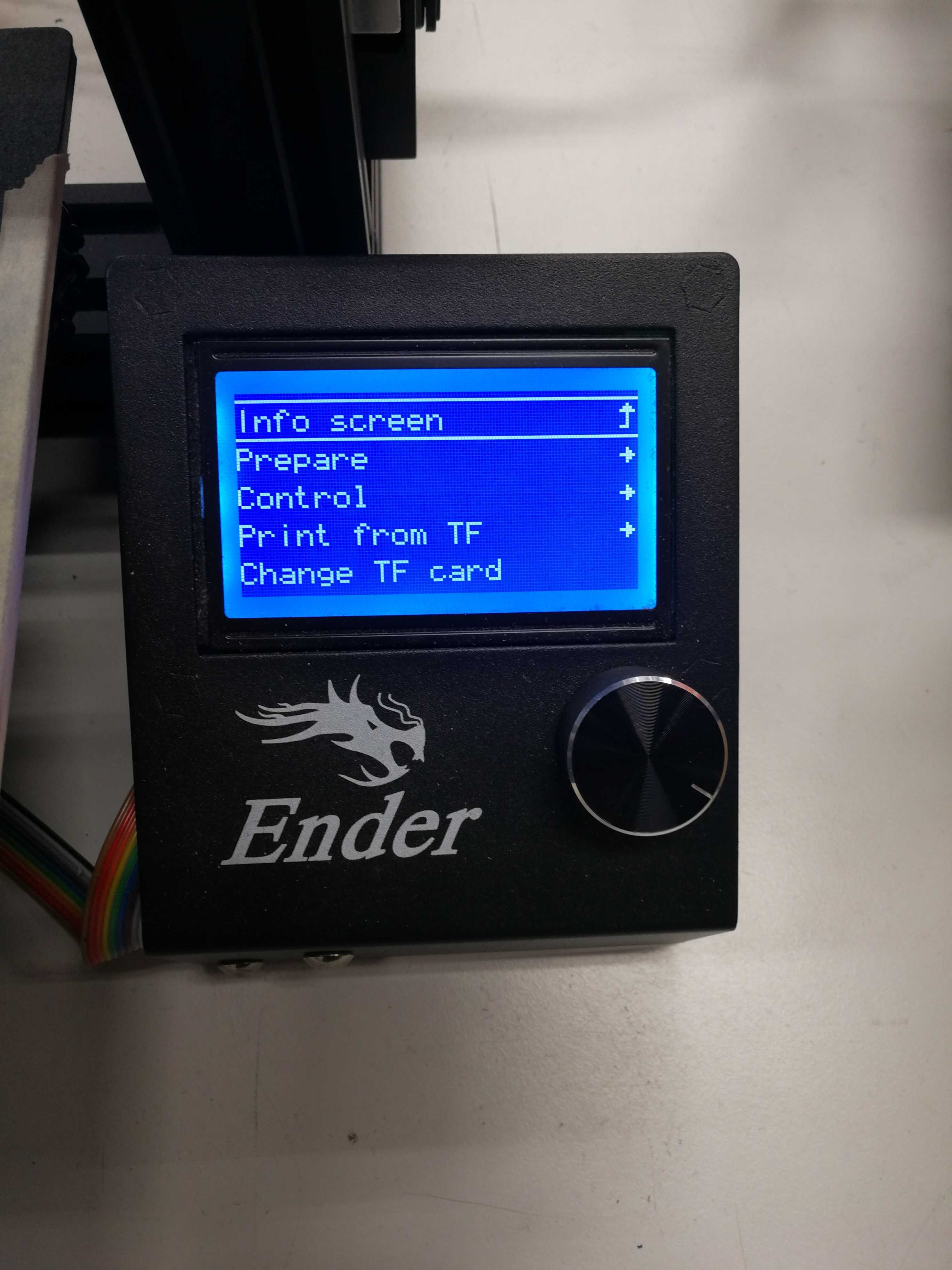
Printing with Ender 3D Printer
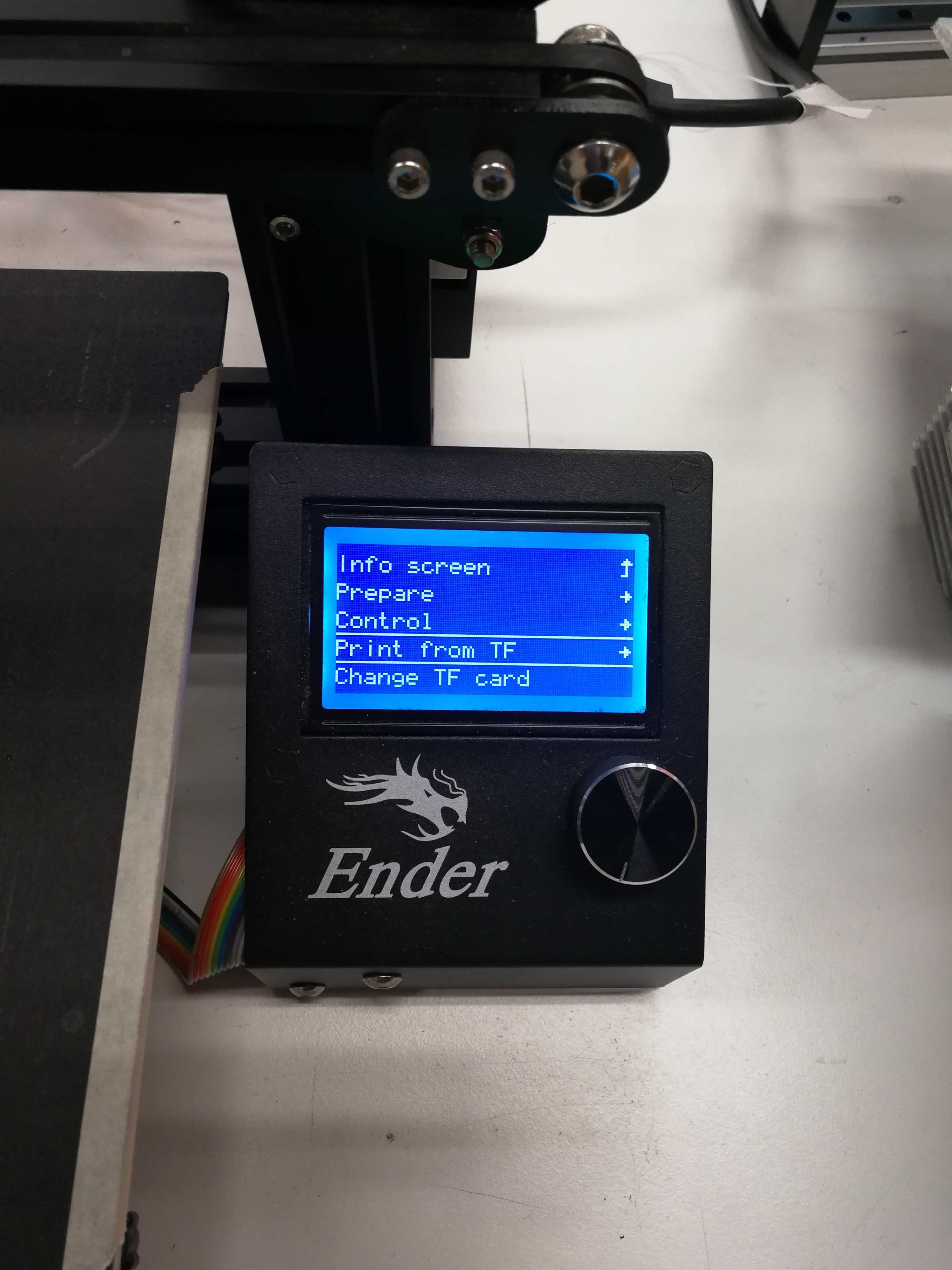
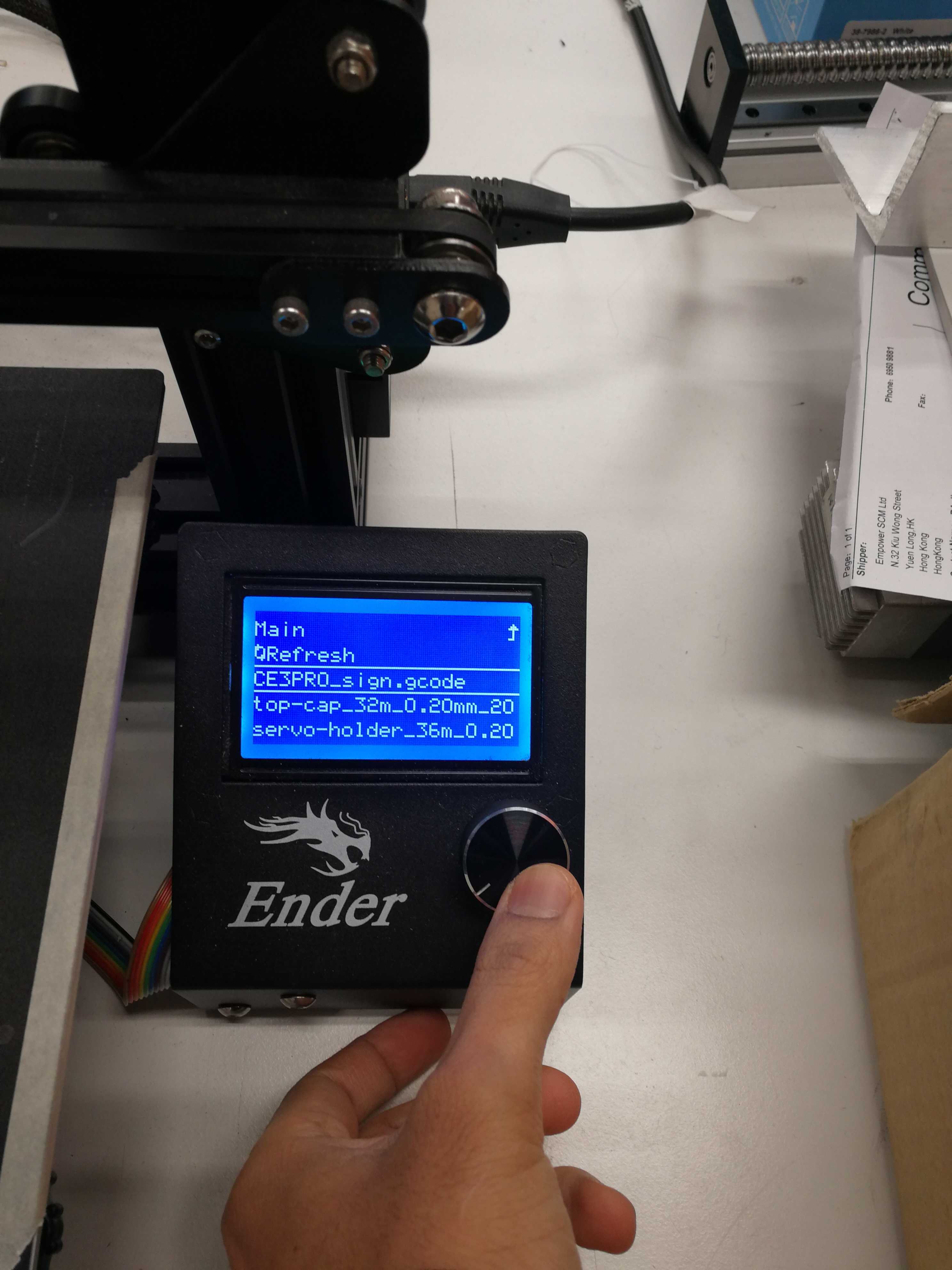
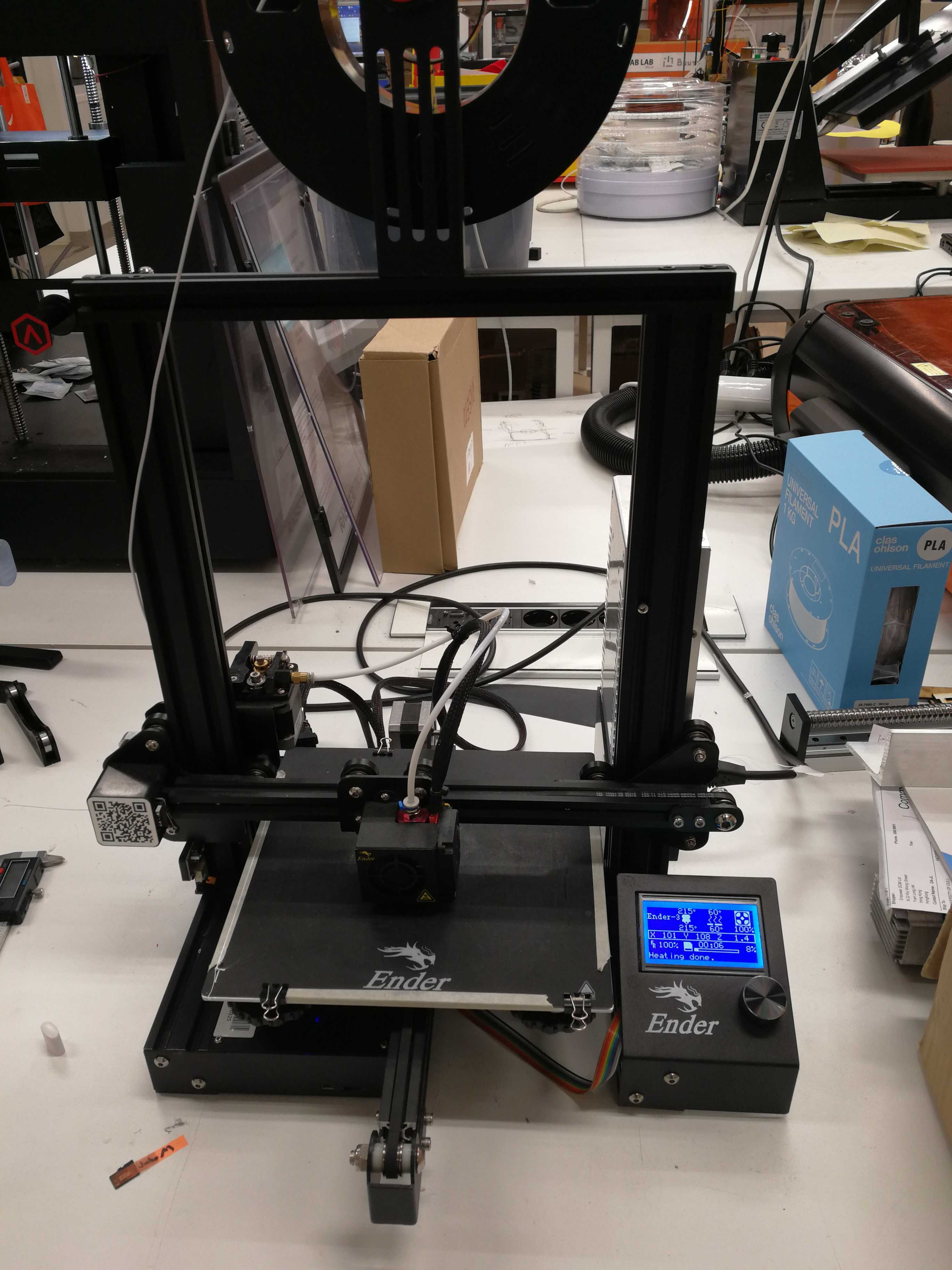
The following figures show steps to print a 3D object from the gscode file generated by the Ultimaker program.
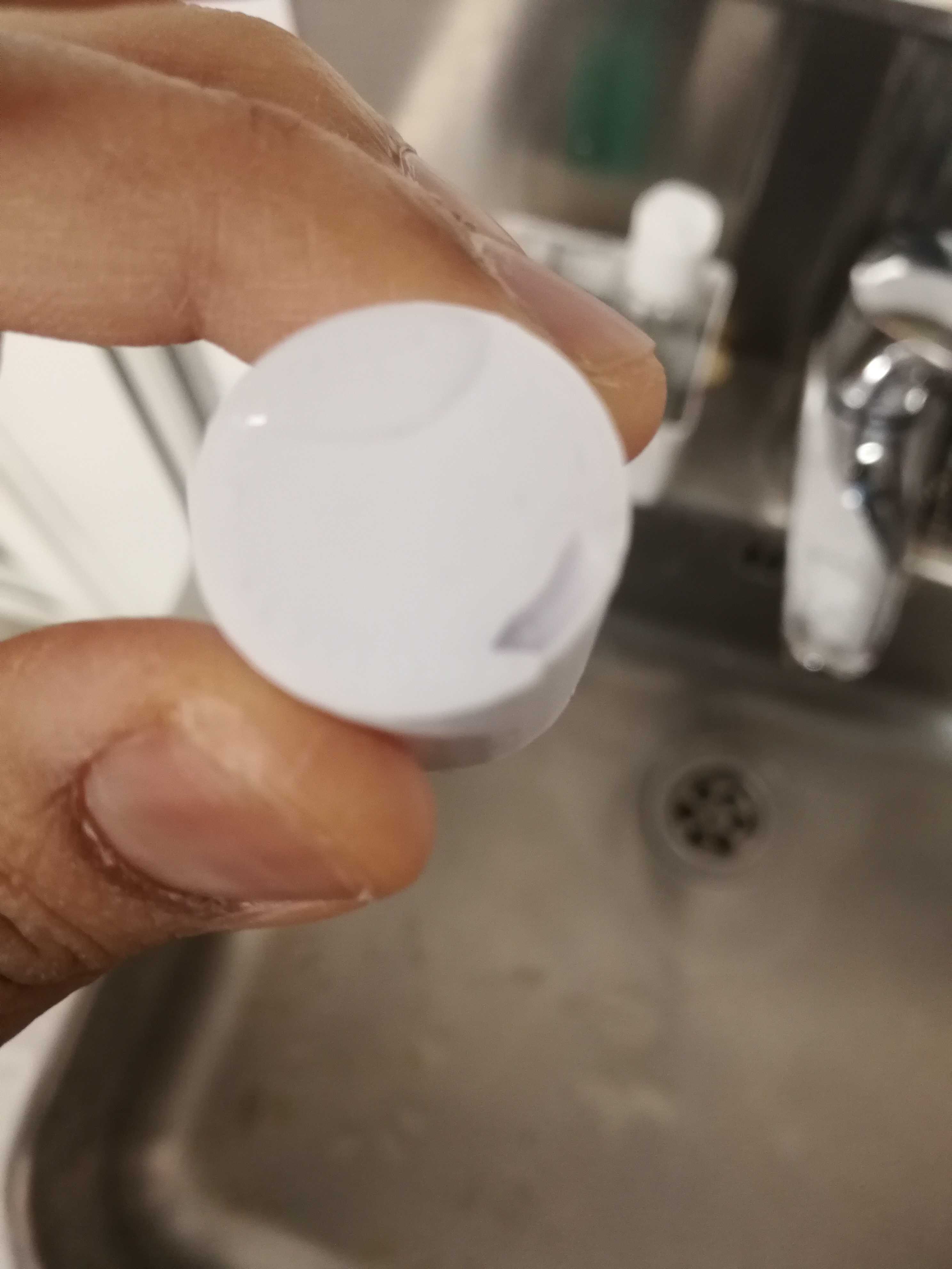
The radius on the spiral was quite small because of which the water droplet took some time to come out from another end.