4. Embedded Programming
This week we started to get to know embedded programming. I have some experience in simple programming of Arduino boards, but already the first session gave me new information on how to install new boards to the Arduino IDE, and where to look for the information on the pins. During the group work, we worked with 3 different microcontrollers (Xiao RP2040, Xiao ESP32C3, and Xiao SAMD21) and learned to use Keysight InfiniiVision DSOX3102A for signal measurements.
Datasheet and board information
From the datasheet, I came to realize the following information about Xiao ESP32C3. It: 1) has a low-power 32-bit RISC-V single-core microprocessor. 2) clock frequency of up to 160 MHz. 3) 84 KB of ROM: for booting and core functions. So, it serves as an ideal choice for low-end embedded applications, such as in IoT or wireless sensor network settings.
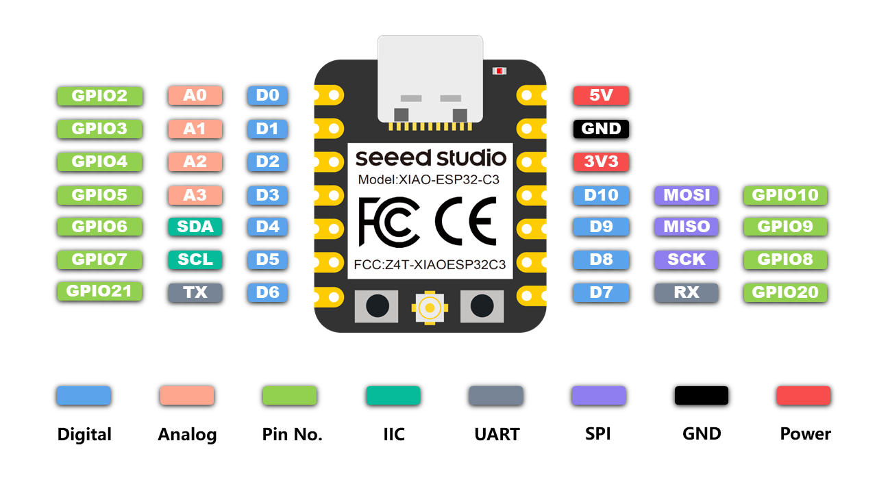
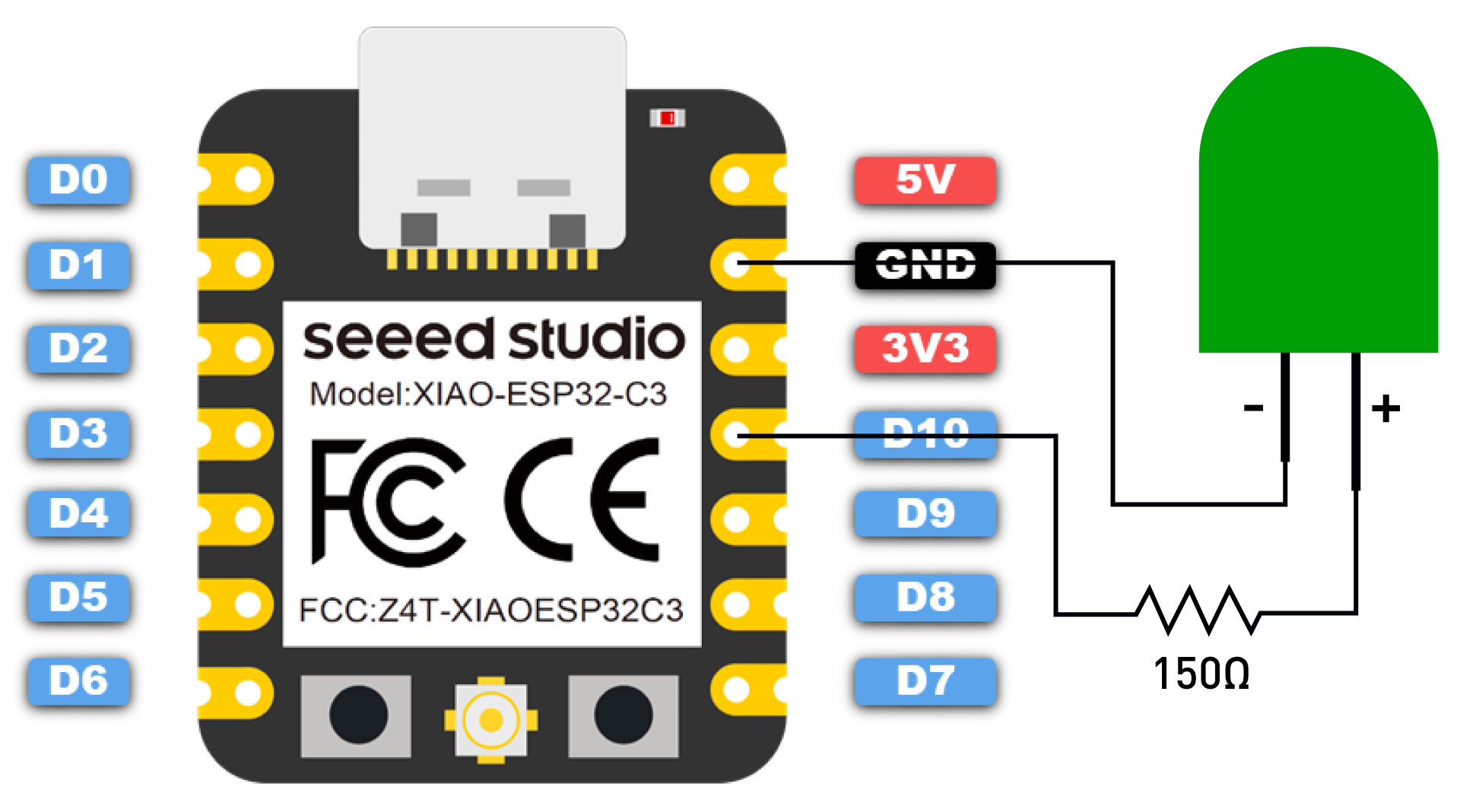
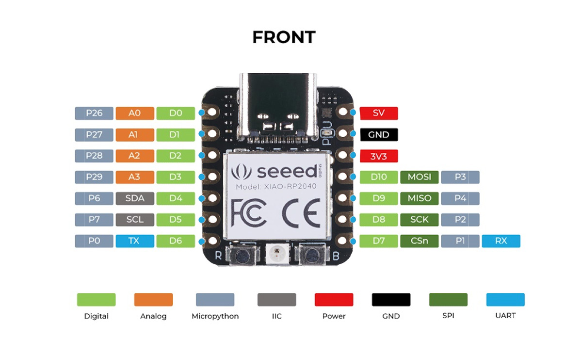
Another key aspect is that input and output can be done only via GPO pins shown in Figure 1.
Installing a new board to Arduino IDE and uploading a simple program to it
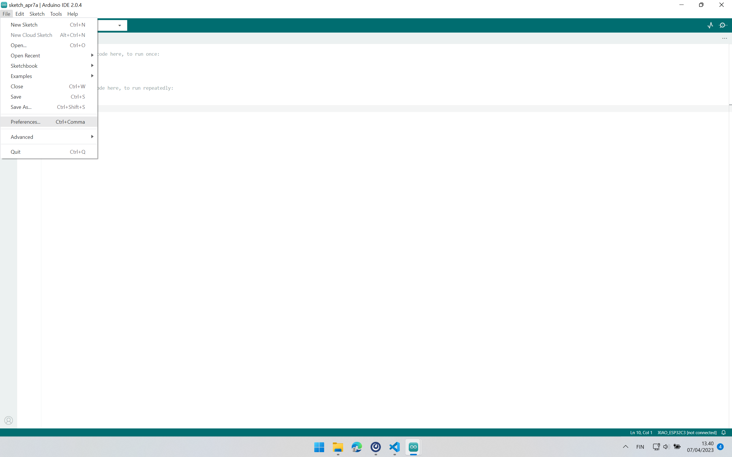
During group work, we worked on installing Arduino IDE 2.0, adding boards, and trying simple blinking example. The following figures demonstrate these steps on Microsoft Windows 10:
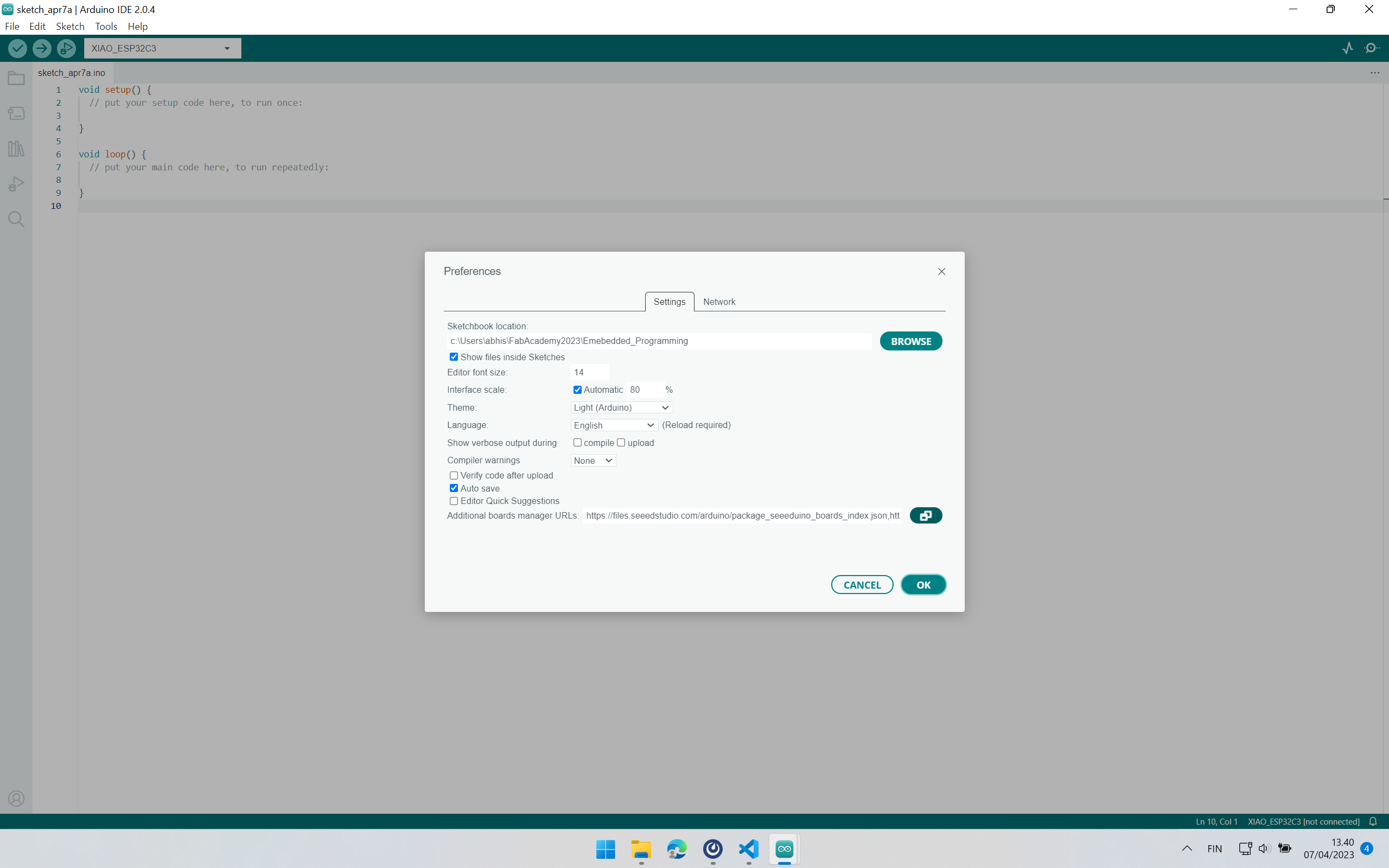
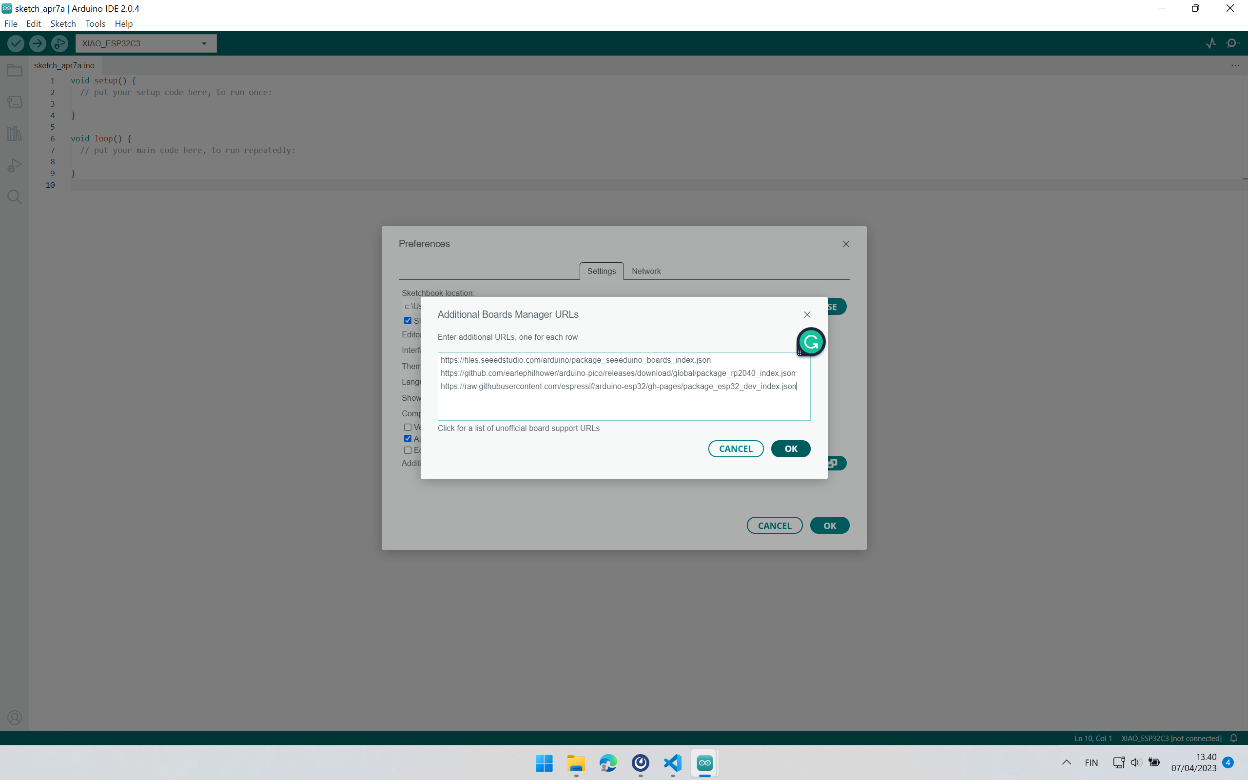
The following board manager URLs are added in Step 3 (Figure 5). Comment (mentioned after “//”) should be removed before adding them to Arduino.
https://files.seeedstudio.com/arduino/package_seeeduino_boards_index.json //Seeed Studio's Board Manager URL
https://github.com/earlephilhower/arduino-pico/releases/download/global/package_rp2040_index.json // Board Manager URL for Xiao RP2040
https://raw.githubusercontent.com/espressif/arduino-esp32/gh-pages/package_esp32_dev_index.json  // Board Manager URL for Xiao ESP32C3
Adding Arduino Cores for Xiao ESP32C3 (Figures 6, 7, and 8):
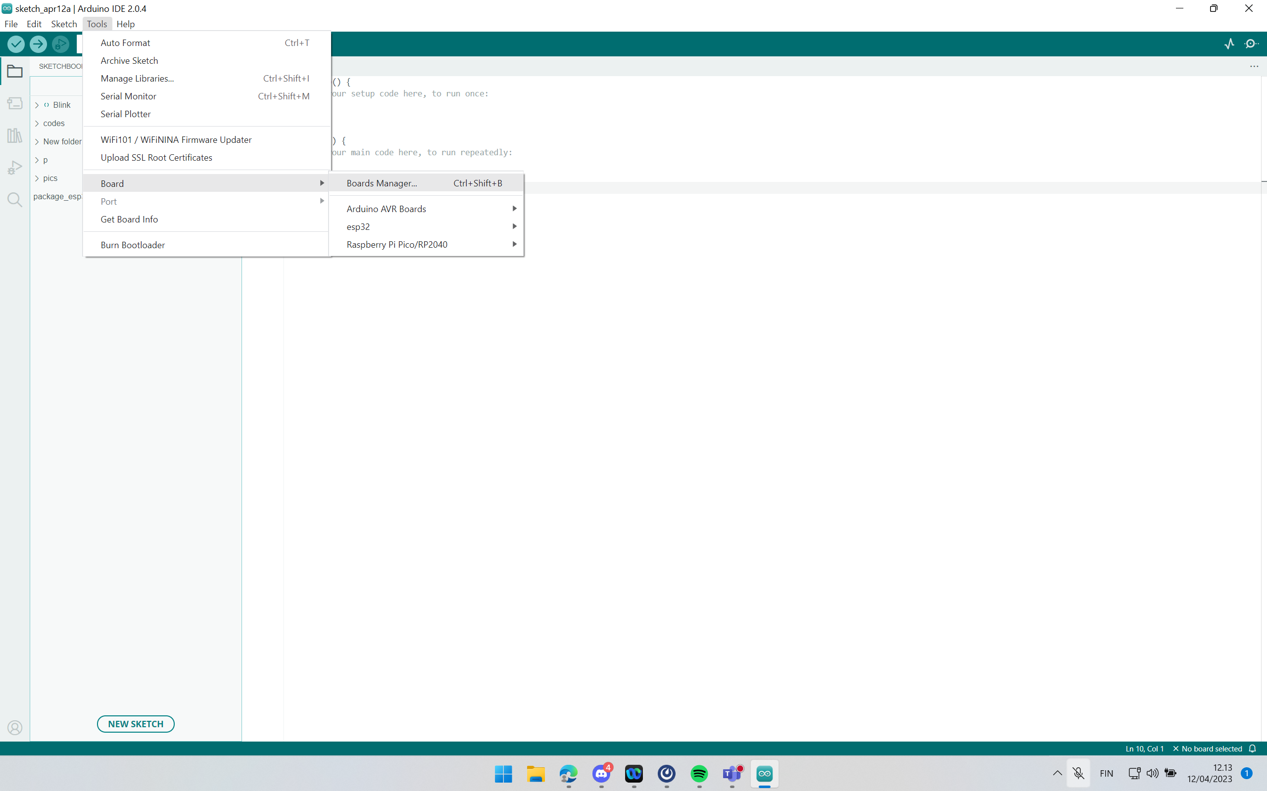
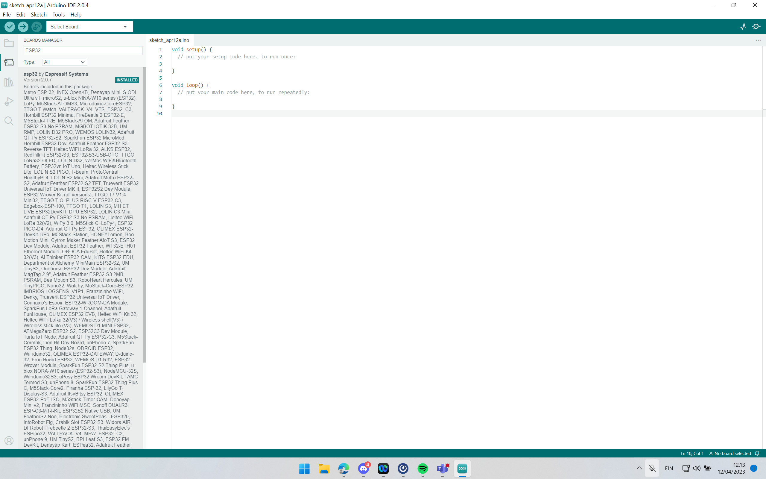
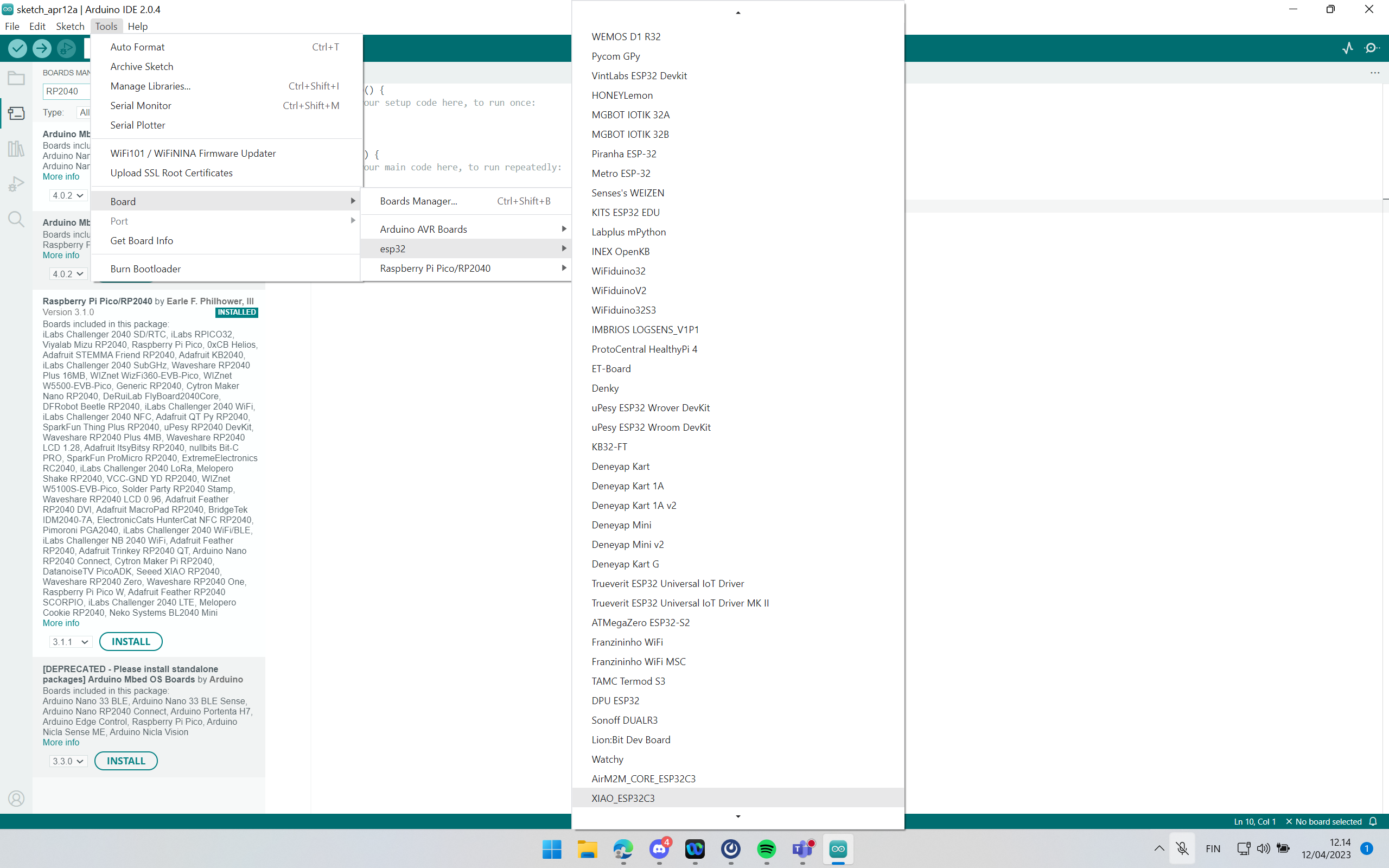
After adding the board manager URL and Arduino core for the board, we need to select the specific board which we have. I worked with Xiao ESP32C3 board, so I chose this board in the step. A similar step can be used to install the Arduino core for Xiao RP2040 by searching the core with the keyword “RP2040” in Figure 7.
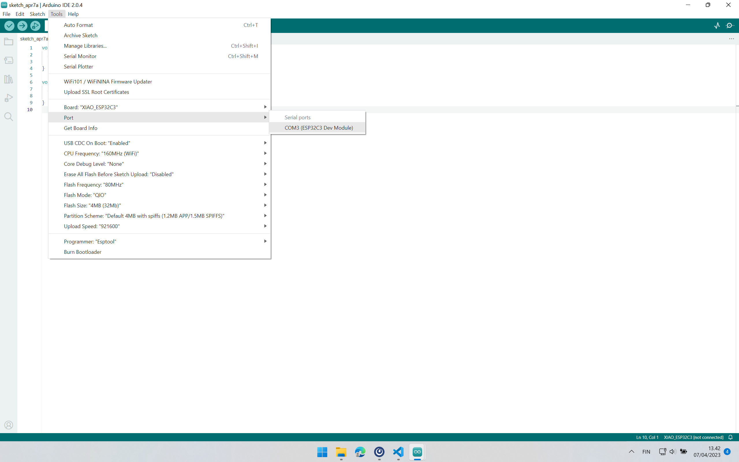
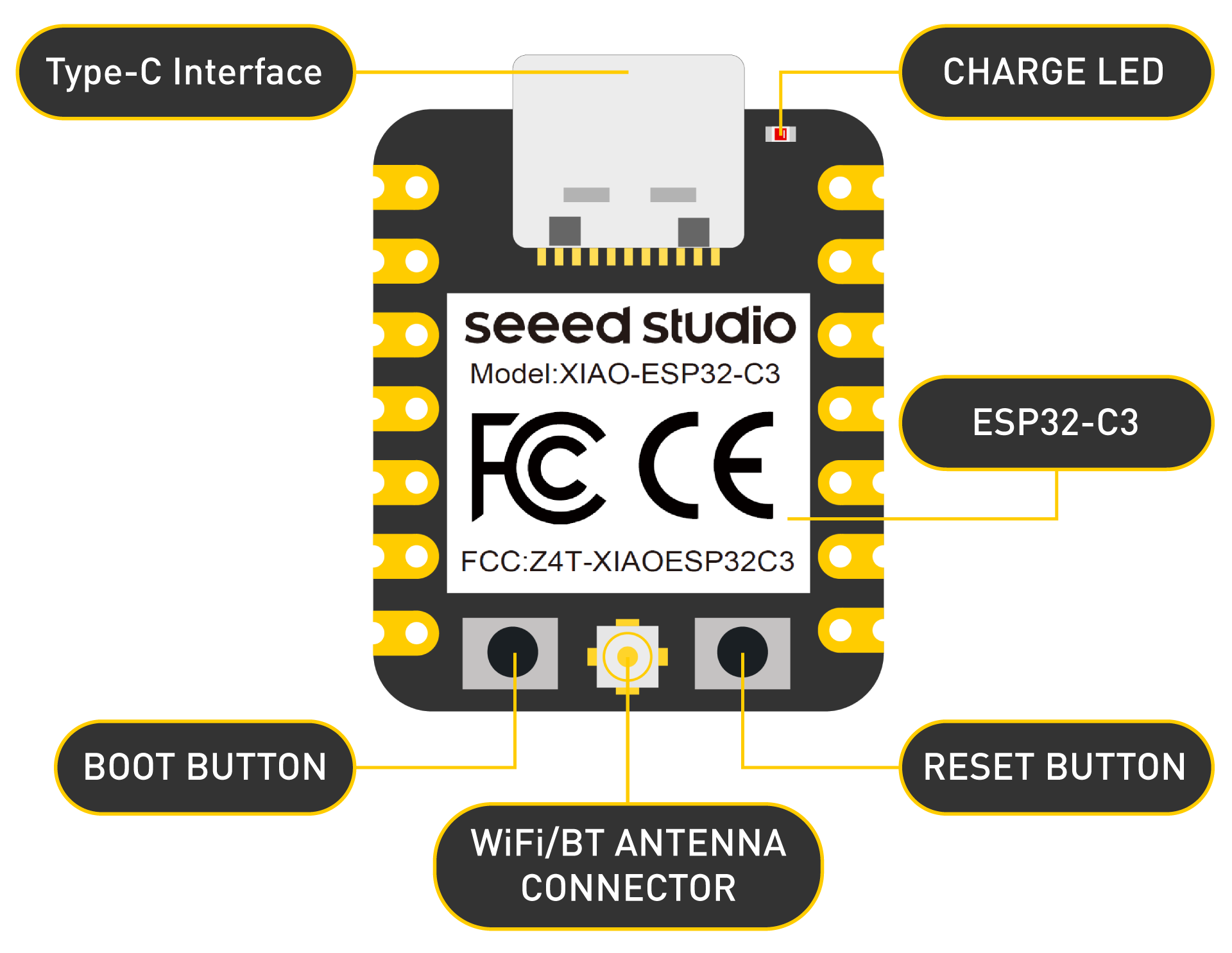
The next step is ensuring that our board is connected to our workstation and Arduino IDE recognizes the connection. It is done by connecting through the port as shown in Step. For the very first connection, the local workstation will need to install a bootloader of the board (aka. analogous to drivers). For Xiao ESP32C3, it is done via (a) disconnecting the board from the workstation, (b) pressing the boot button on the board, connecting the board to the workstation while the boot button is still pressed, then releasing the boot button on the board. Afterwards, the port can be selected as shown in the figure. The Port is usually COM level 3 or higher.
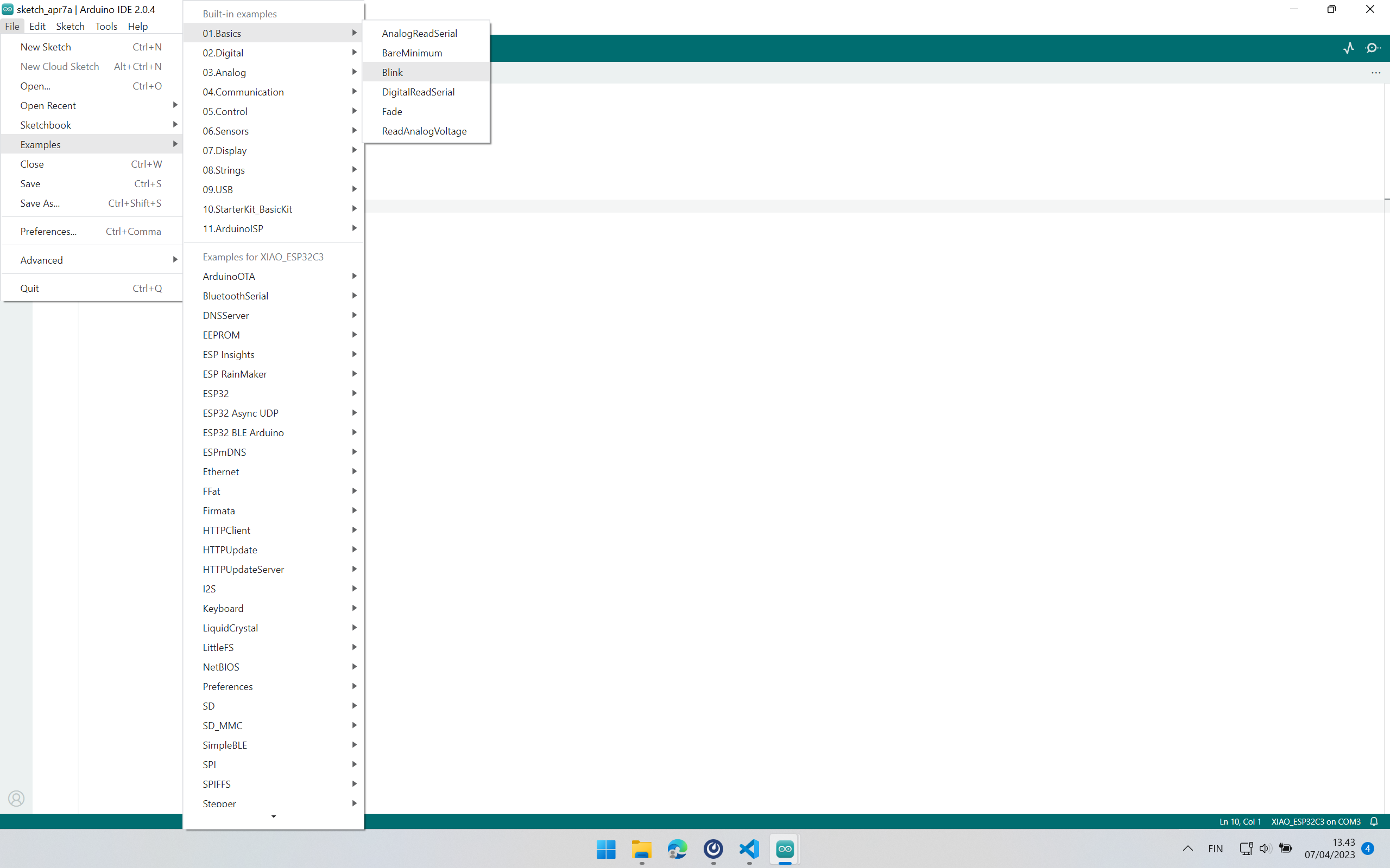
Next, we want to try a simple blink example. Arduino IDE has some pre-installed examples. The “Blink” example can be selected as shown in the figure.
The program binks on and off every 1 second. LED is connected to the board via D10. The Board sends the command to LED to blink on and off every one second via this pin D10.
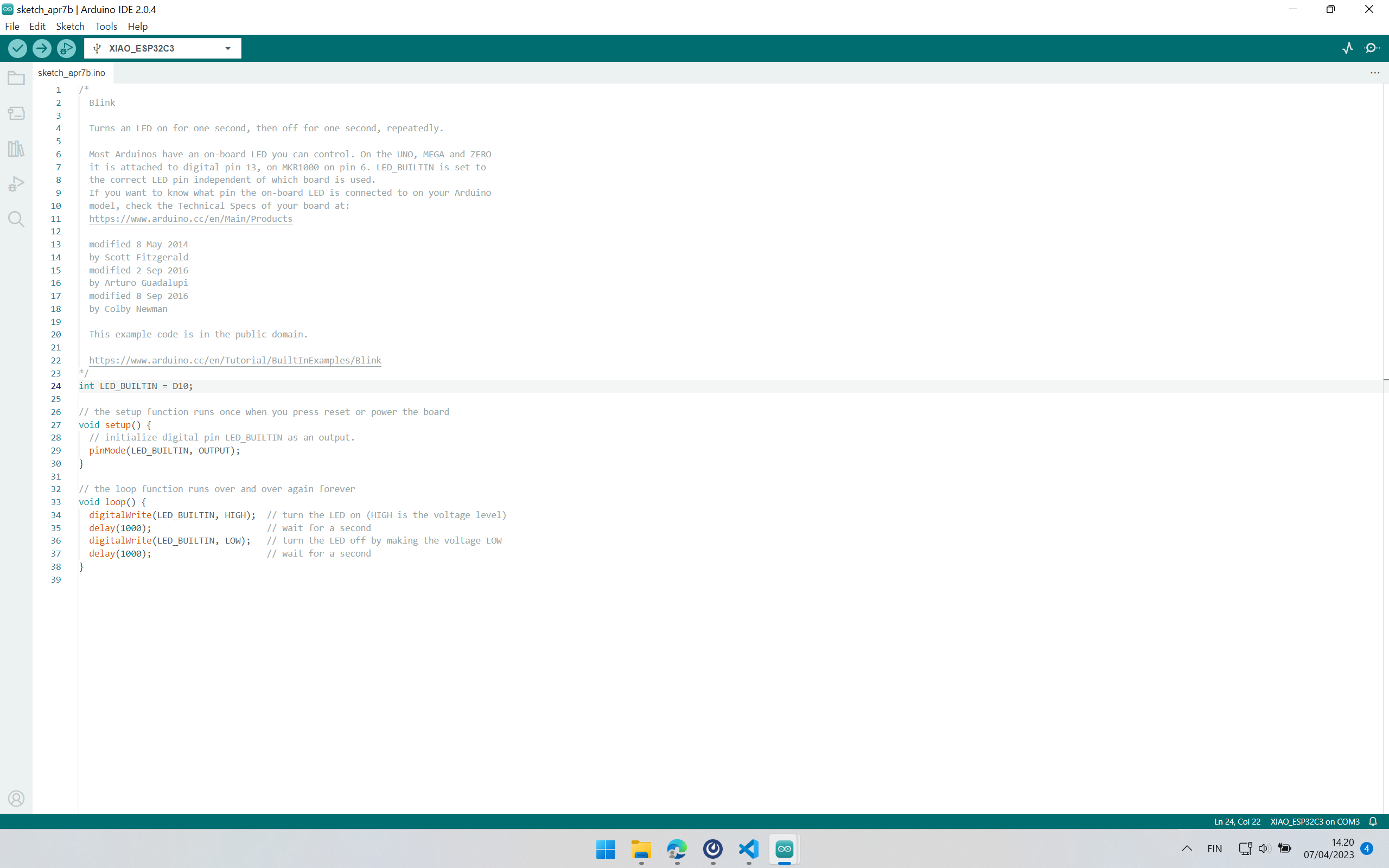
The next step is compiling the program. The tickmark within the yellow circle needs to be pressed for compiling the program
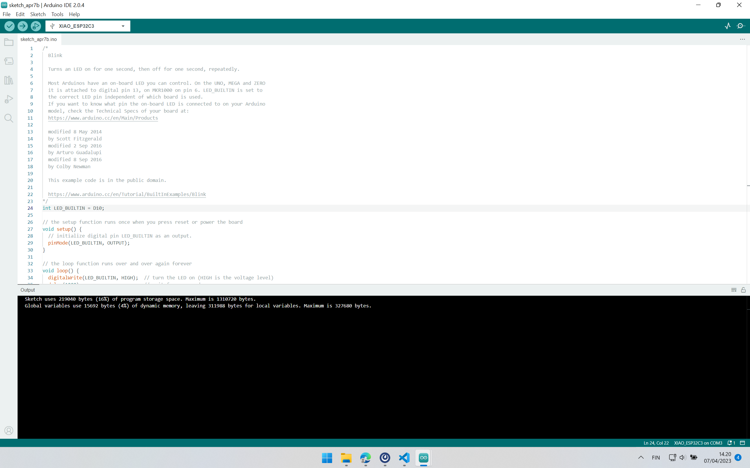
If the program does not have any syntax error, it compiles successfully, and next step is to upload the program to the board. The horizon arrow in the figure needs to be clicked to initiate the upload process. By default, upload also first compiles the program before uploading it to the board
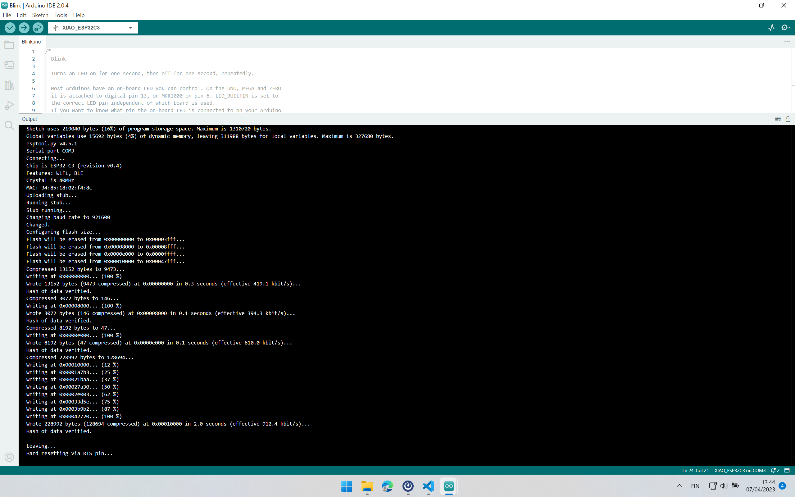
The figure shows the output of the compilation and uploading of the program. “Hard resetting via RTS pin…” message indicates that the program has been uploaded to the board successfully. After this, the hardware setup should exhibit what was in the program. Sometimes, the Xiao ESP32C3 board requires the “Press and Release” of Reset button on the board once to reflect the program outcomes.
Hardware setup
The hardware connection setup was done as shown in the figure below with help of a tutorial on Seeedstudio.
Demo Video
The following demo video shows the blinking of the LED every 1 second with help of Xiao ESP32C3 MCU.
Reading Temperature and Humidity data and Displaying them
I used the DHT11 sensor to collect Temperature and Humidity data in real-time and OLED Display to display those data with help of the Xiao ESP32C3 MCU board.
Adding these two additional components requires installing their corresponding libraries and including them in the program. The following figures show steps to install a new library from Arduino IDE.
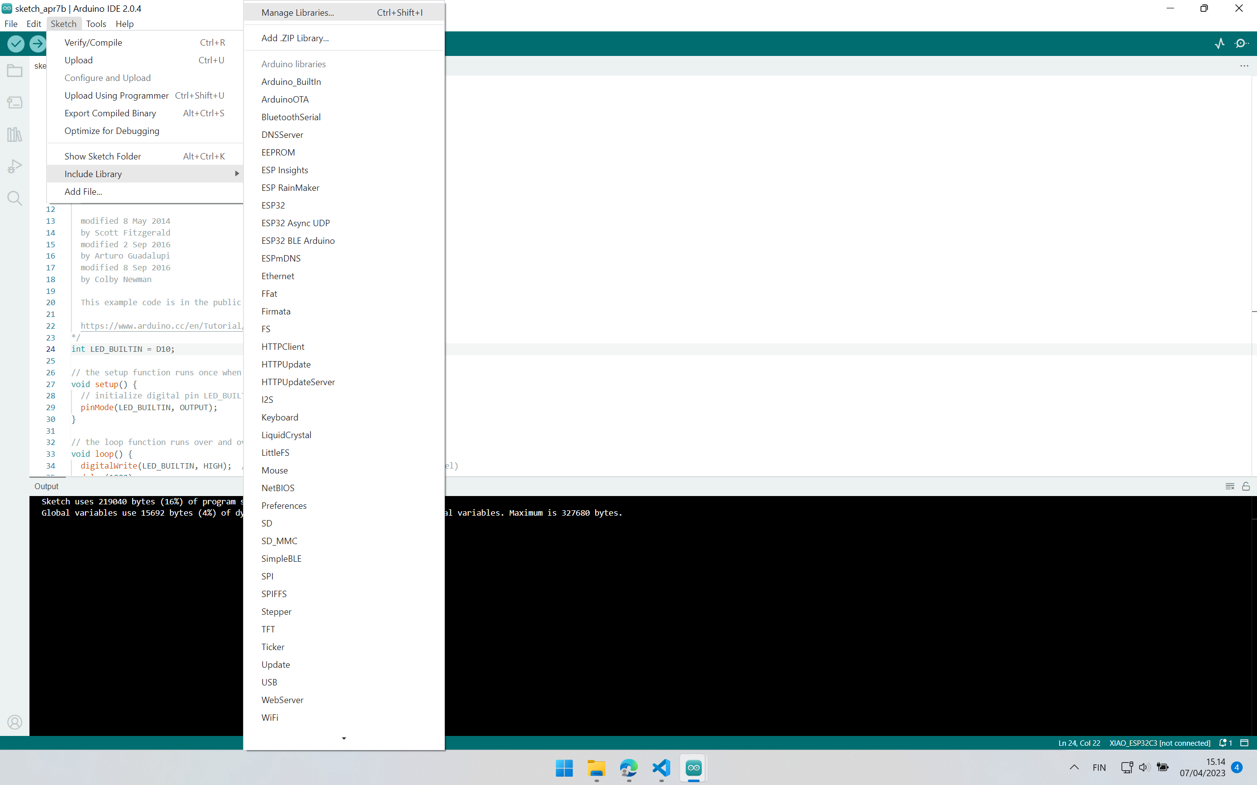
It is also possible to add a library by following “Add .ZIP Libraries…” option as shown in the figure. It requires downloading the corresponding library (as a Zip file) on the local workstation in advance.
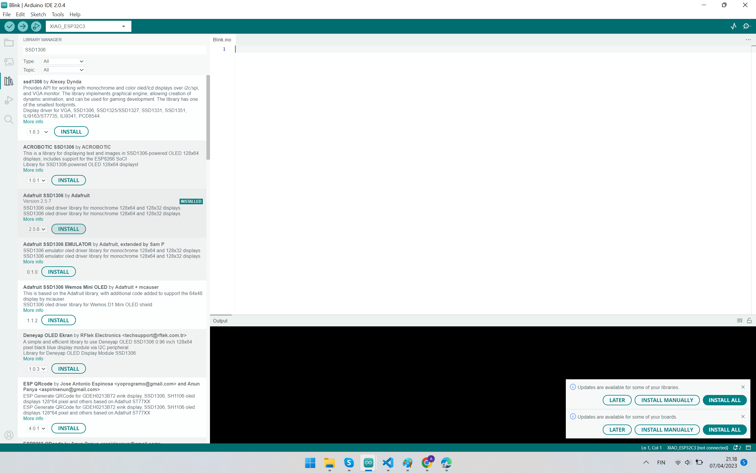
A similar step can be used for including libraries for OLED Displays. Oled Display’s library can be included by including these libraries: “Adafruit SSD 1306” and “Adafruit GFX Library”. Adafruit components also require including the “Adafruit Bus IO” library.
Hardware setup
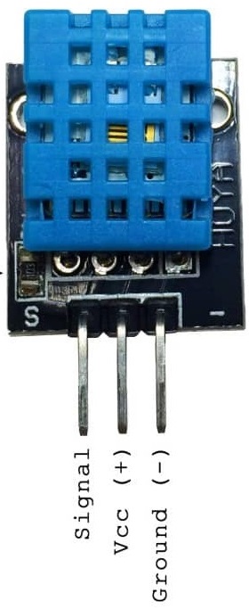
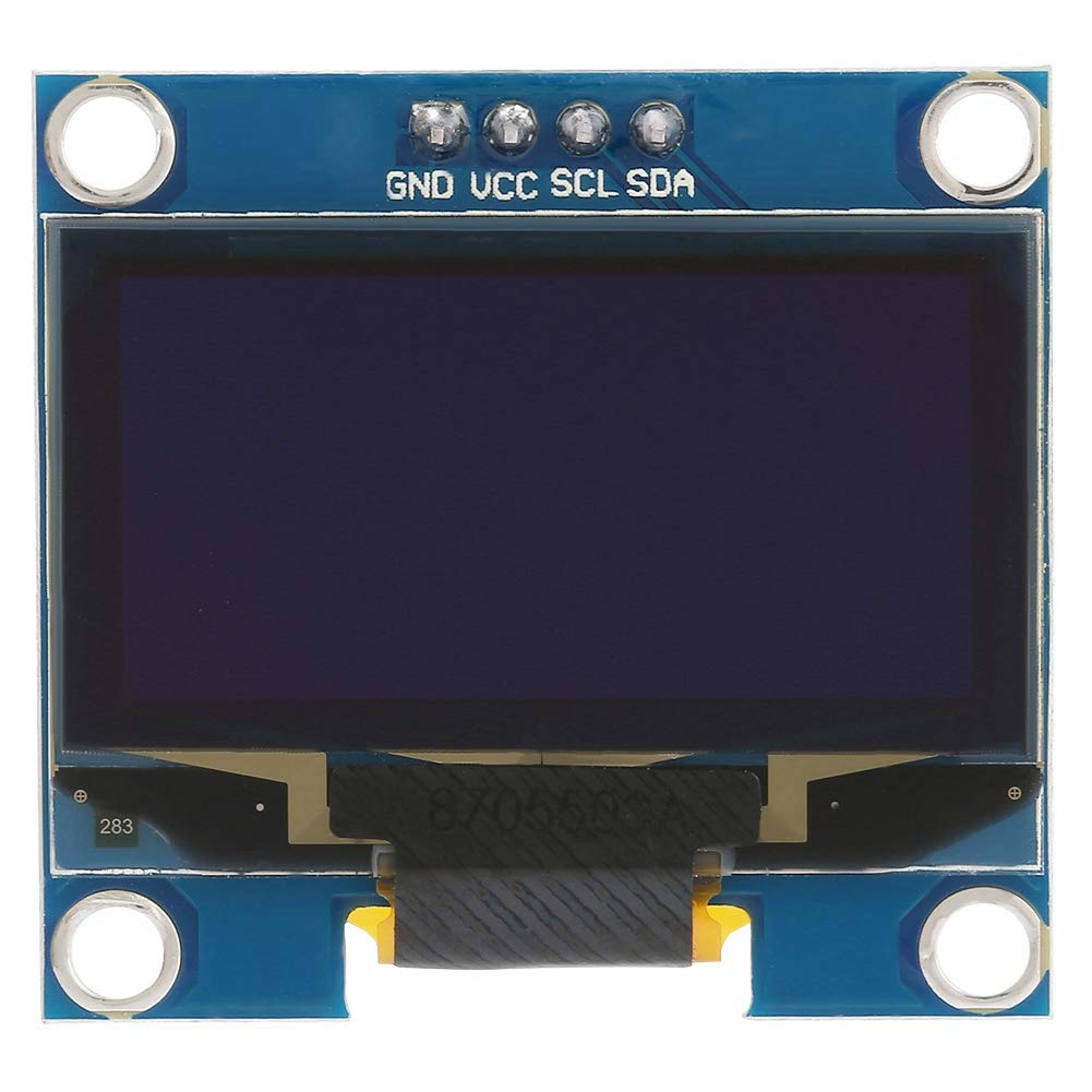
VCC and GND of the DHT11 sensor and OLED display are connected to 5V and GND pins of Xiao ESP32C3 respectively. The signal pin of the DHT11 sensor is connected GPI05 pin of the Xiao ESP32C3 board. SCL and SDA pins of the OLED display are connected to GPI07 and GPI06 pins on the Xiao ESP32C3 board respectively, and finally, the Xiao ESP32C3 board is connected to the local workstation via USB connection.
Code
The following code needs to be compiled and then uploaded to the Xiao ESP32C3 board from Arduino IDE. The program logic allows sensing temperature and humidity data and then displaying these on an OLED display via SPI pins. Sensing happens after every 2 seconds. These data are also displayed on Arduino IDE’s serial monitor.
#include <DHT.h>
#include <DHT_U.h>
#define DHTPIN 5     // Digital pin GPI05 on Xiao ESP32C3 connected to the DHT sensor
#define DHTTYPE DHT11   // DHT 11
DHT dht(DHTPIN, DHTTYPE);
#include <SPI.h>
#include <Wire.h>
#include <Adafruit_GFX.h>
#include <Adafruit_SSD1306.h>
#define SCREEN_WIDTH 128 // OLED display width, in pixels
#define SCREEN_HEIGHT 32 // OLED display height, in pixels

// Declaration for an SSD1306 display connected to I2C (SDA, SCL pins)
// The pins for I2C are defined by the Wire-library.
// On an arduino UNO:       A4(SDA), A5(SCL)
// On an arduino MEGA 2560: 20(SDA), 21(SCL)
// On an arduino LEONARDO:   2(SDA),  3(SCL), ...

#define OLED_RESET     -1 // Reset pin # (or -1 if sharing Arduino reset pin)
#define SCREEN_ADDRESS 0x3C ///< See datasheet for Address; 0x3D for 128x64, 0x3C for 128x32
Adafruit_SSD1306 display(SCREEN_WIDTH, SCREEN_HEIGHT, &Wire, OLED_RESET);

#define NUMFLAKES     10 // Number of snowflakes in the animation example

int count=1;

#define LOGO_HEIGHT   16

#define LOGO_WIDTH    16
static const unsigned char PROGMEM logo_bmp[] =
{ 0b00000000, 0b11000000,
  0b00000001, 0b11000000,
  0b00000001, 0b11000000,
  0b00000011, 0b11100000,
  0b11110011, 0b11100000,
  0b11111110, 0b11111000,
  0b01111110, 0b11111111,
  0b00110011, 0b10011111,
  0b00011111, 0b11111100,
  0b00001101, 0b01110000,
  0b00011011, 0b10100000,
  0b00111111, 0b11100000,
  0b00111111, 0b11110000,
  0b01111100, 0b11110000,
  0b01110000, 0b01110000,
  0b00000000, 0b00110000 };

void setup()
{
  Serial.begin(115200);
  if(!display.begin(SSD1306_SWITCHCAPVCC, 0x3C)) { // Address 0x3D for 128x64
    Serial.println(F("SSD1306 allocation failed"));
    for(;;);
  }
  dht.begin();
  delay(2000);
}

void loop()
{
  float h = dht.readHumidity();
  float t = dht.readTemperature();
  // Check if any reads failed and exit early (to try again).
  if (isnan(h) || isnan(t))
  {
    Serial.println(F("Failed to read from DHT sensor!"));
    return;
  }

  display.clearDisplay();
  display.setTextSize(1);
  display.setTextColor(WHITE);
  display.setCursor(0, 0);
  display.println(F("[Sender]"));
  display.print(F("Count: "));
  display.println(count);
  display.print(F("Humidity: "));
  display.print(h);
  display.println("%");
  display.print(F("Temperature: "));
  display.print(t);
  display.println(F(" C "));
  display.println("");
  display.display();

  Serial.print(F("Count: "));
  Serial.println(count);
  Serial.print(F("Humidity: "));
  Serial.print(h);
  Serial.println("%");
  Serial.print(F("Temperature: "));
  Serial.print(t);
  Serial.println(F("°C "));
  Serial.println("");

  count=count+1;
  delay(2000);
}
Demo Video
The following demo video (hosted on YouTube under CCL) shows sensing of humidity and temperature data via a DHT11 sensor and displaying them on an OLED display as well as an Arduino Serial Monitor with help of Xiao ESP32C3 MCU.
Extra Credit Assignment: Blinking LED with different language and environment
In previous experiments, the “Arduino IDE” programming environment, “C programming language” and “Xiao ESP32C3” development board have been used. For extra assignment task, I have worked with “Thorny” programming environment, “Micropython” programming langauge, and “Xiao RP2040” development board.
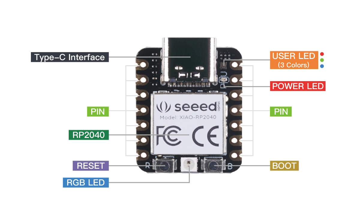
Xiao RP2040 Datasheet
From the datasheet, I came to realize the following information about Xiao Rp2040. It: 1) has a Dual Cortex M0+ processor cores which can support clock frequency up to 133 MH. 2) 264KB of SRAM and 2MB of onboard Flash memory. 3) can support multiple languages (Micropython/Arduino/CircuitPython).
Most importantly, it has 14 GPIO PINs, on which there are 11 digital pins, 4 analog pins, 11 PWM Pins,1 I2C interface, 1 UART interface, 1 SPI interface, and 1 SWD Bonding pad interface. For programmable input and output interfaces, only these 11 digital pins can be used.
Also, it seems that Xiao ESP32C3 is more powerful than Xiao RP2040 in terms of speed (i.e. clock frequency).
Hardware setup
I followed instructions from Seeed Studio’ site to set up the programming environment. The circuit schematics are similar to the blinking experiment with Xiao ESP32C3 mentioned above in Figure 1, except for one difference the positive node of LED is connected to pin P0 on Xiao RP2040.
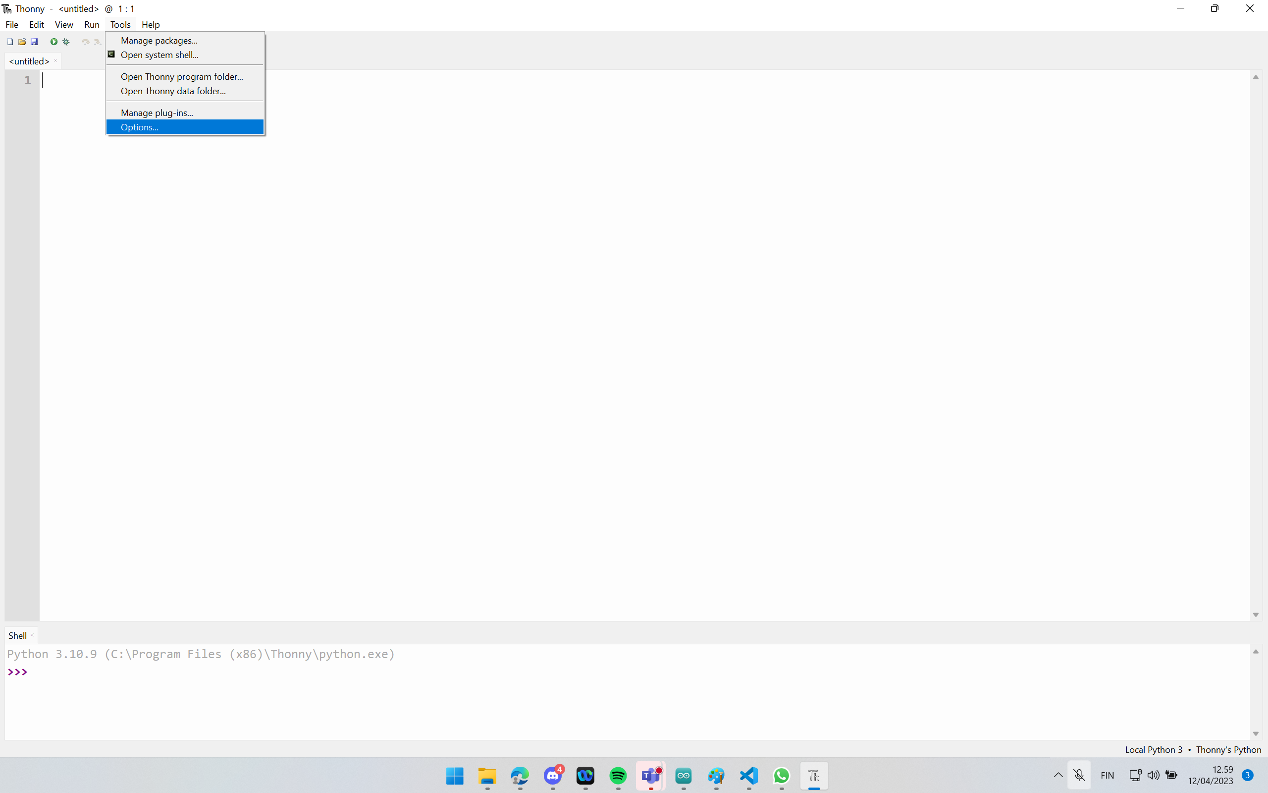
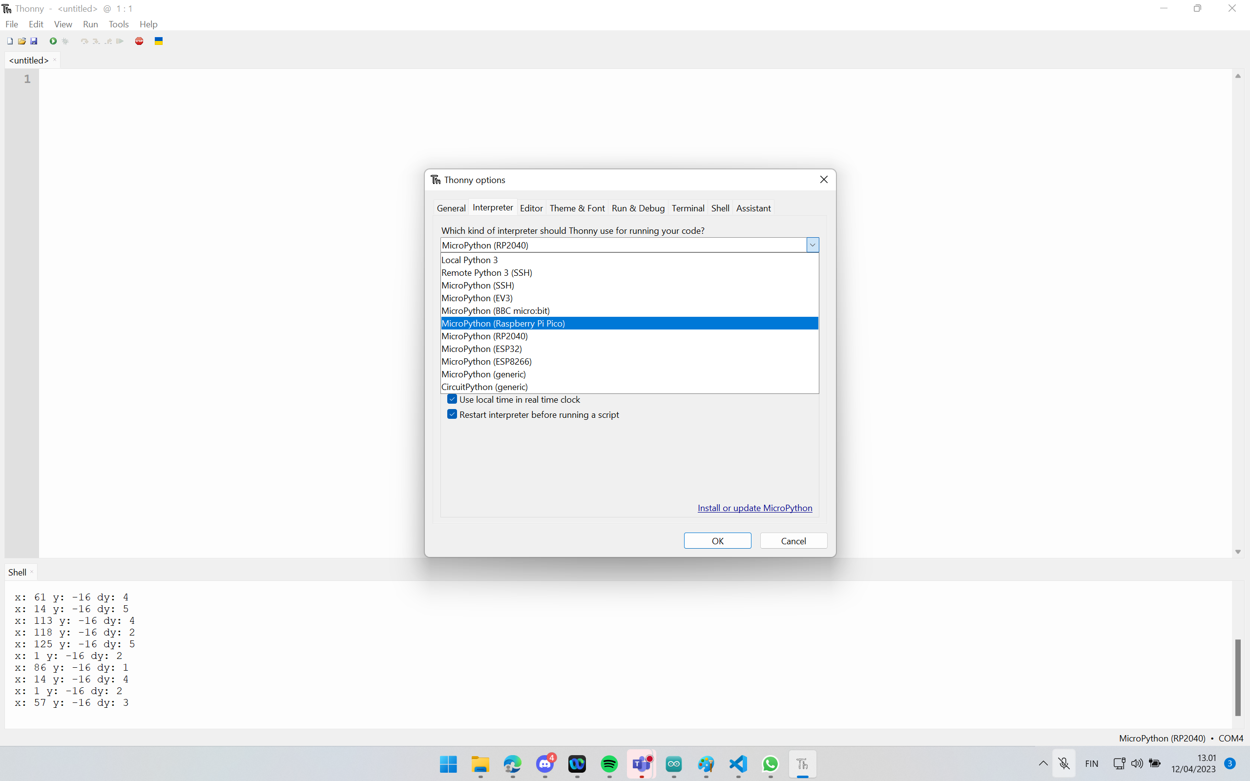
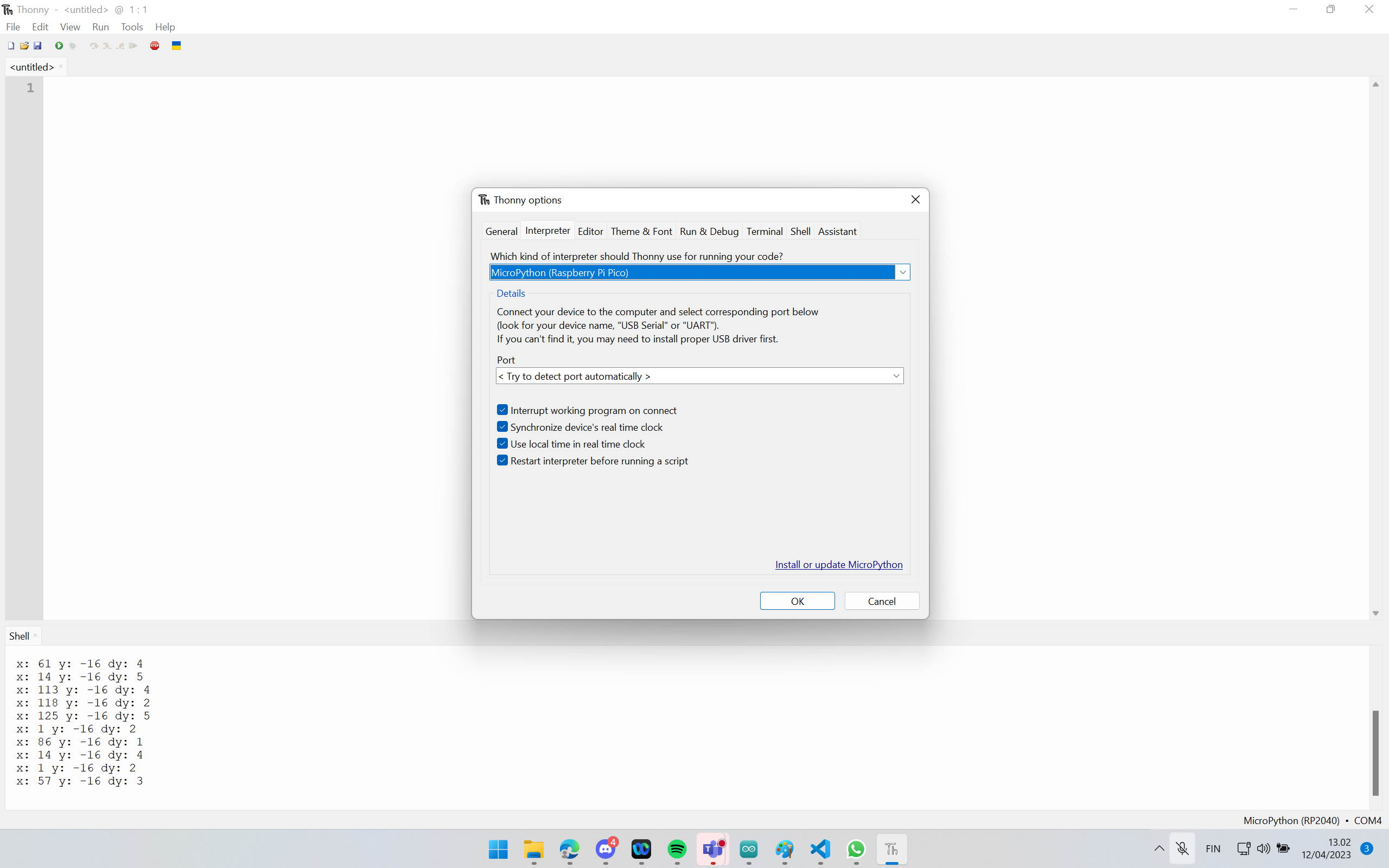
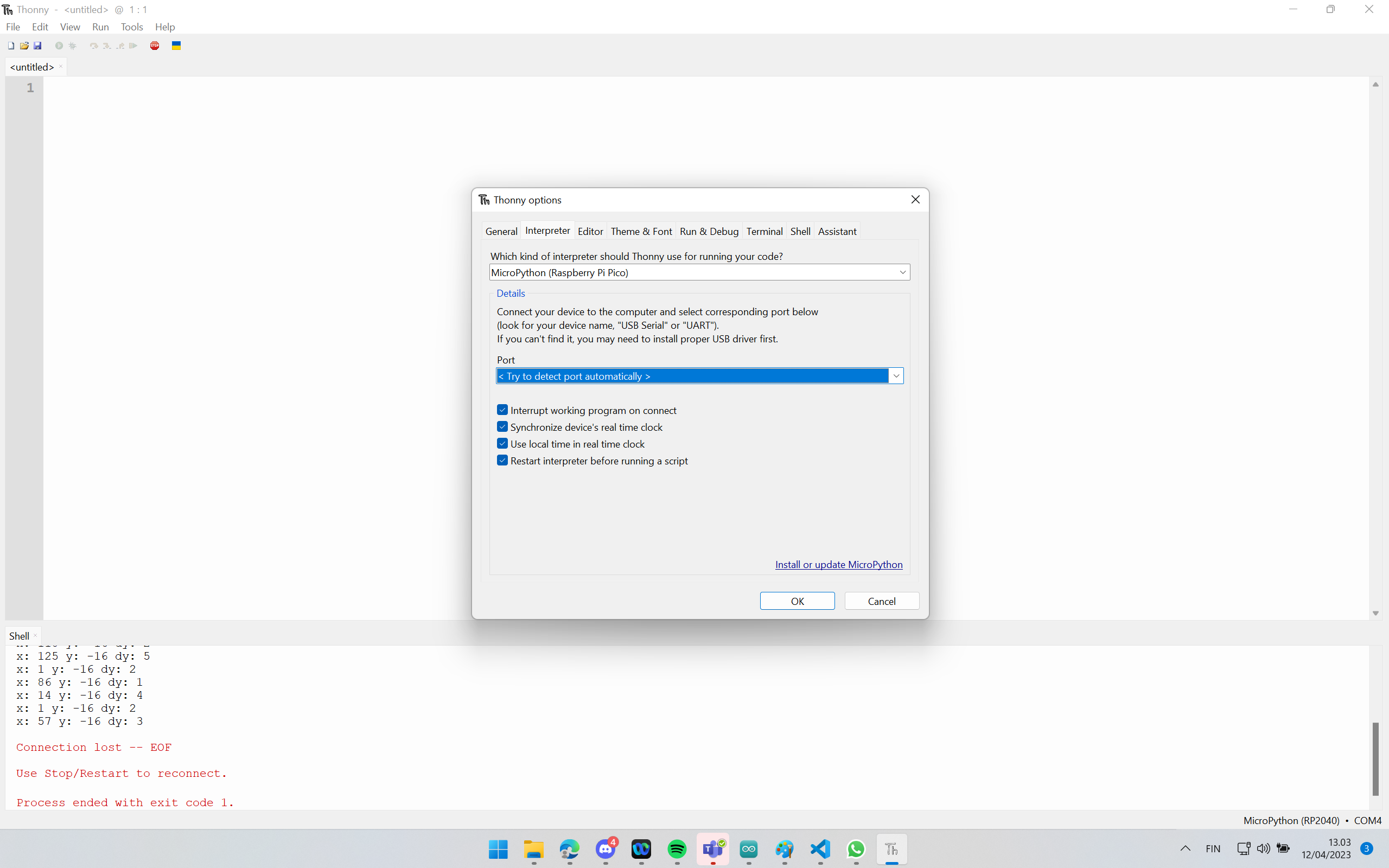
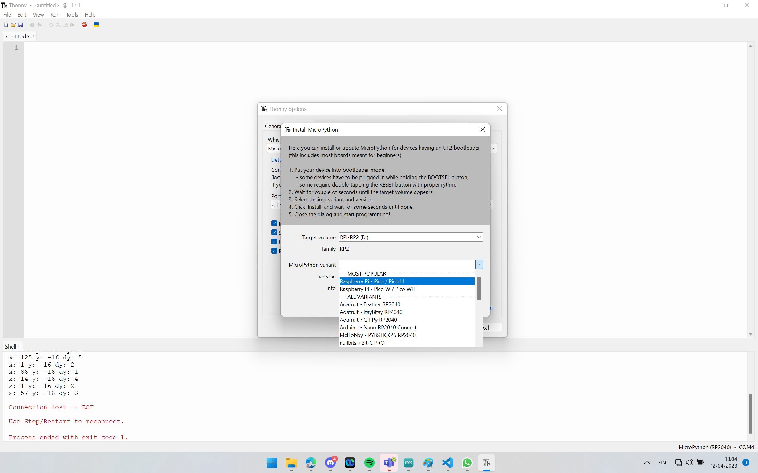
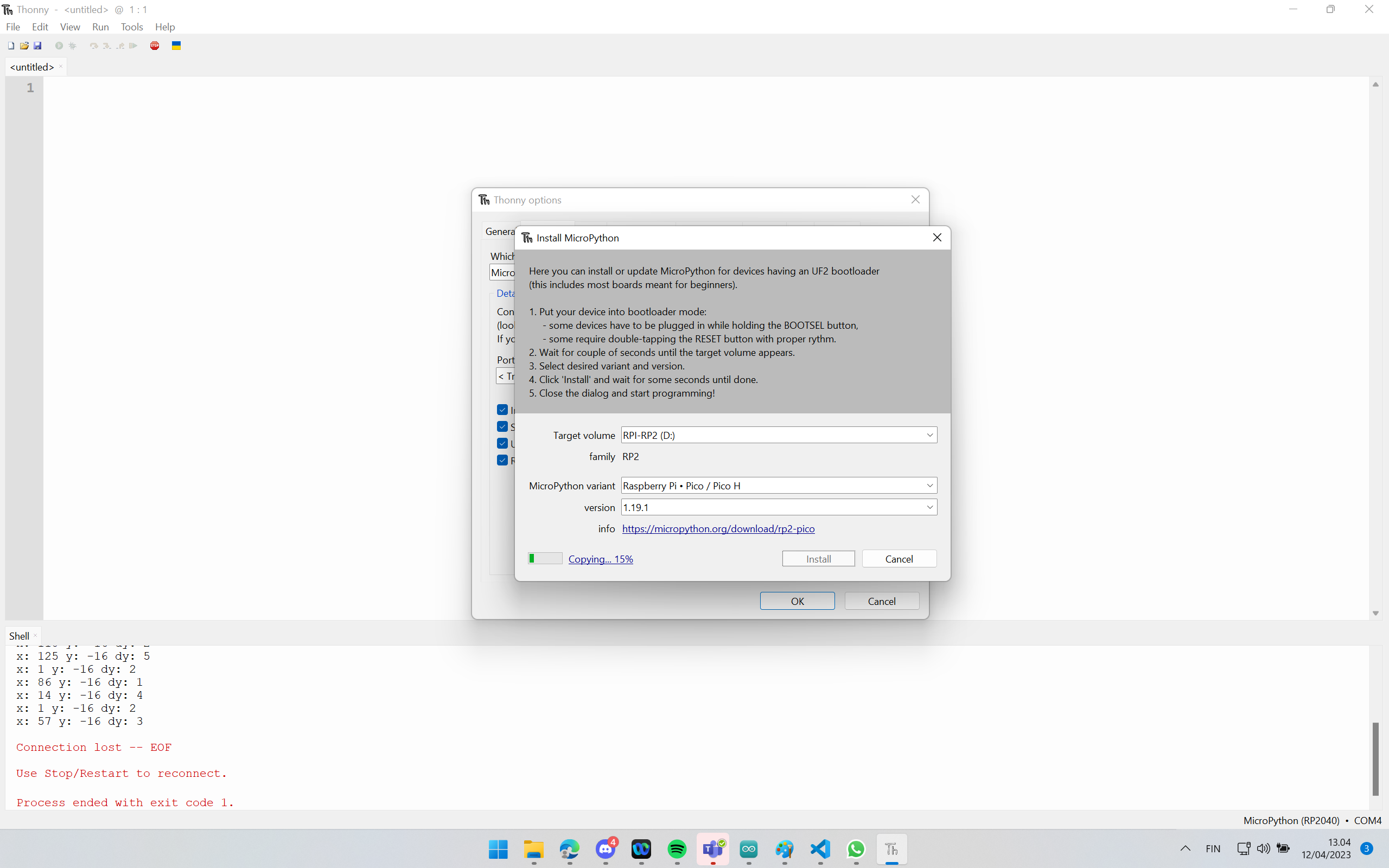
1) First we need to download and install Thorny IDE on the workstation. 2) Xiao RP2040 should be then connected and identified in Thory before installing MicroPython. For this, the “Boot” button on the board should be pressed while attaching it to the computer port. 3) Figures 21-26 illustrate the process of installing Micropython for Xiao RP2040 in Thorny IDE.
Code
The following code written in Micropython blinks LED on and off every other two seconds. The code was originally taken from Seeed Studio’s site. I modified the code at two places mentioned below as a comment to make it work with
from machine import Pin, Timer

led = Pin(25, Pin.OUT)
p2 = Pin(0, Pin.OUT)     # create input pin on P0, I added
Counter = 0
Fun_Num = 0

def fun(tim):
    global Counter
    Counter = Counter + 1
    led.value(Counter%2)
    p2.value(Counter%2) # LED blinking every other two seconds, I added.

tim = Timer(-1)
tim.init(period=2000, mode=Timer.PERIODIC, callback=fun)
The above-mentioned code should be copied to Thorny Editor. Then, the code should be uploaded to the board by clicking the “Run current script” button. For the first time, Thorny asks where to save the code (This Computer, and Raspberry Pi Pico). Both This Computer and Raspberry Pi Pico are fine. To check the program outcome on the board, it must be uploaded to the Raspberry Pi Pico.
Demo Video
The following demo video shows the blinking of the LED every 1 second with help of Xiao RP2040 MCU (and a program written in Micropython).