9. Output devices
This week we got to know how to use output devices. During the group work, we measured the current (I) consumption of a neopixel led strip. Since the voltage U was 5V, the power could be calculated as P=UI.
Showing Output on Neopixel LED Strip
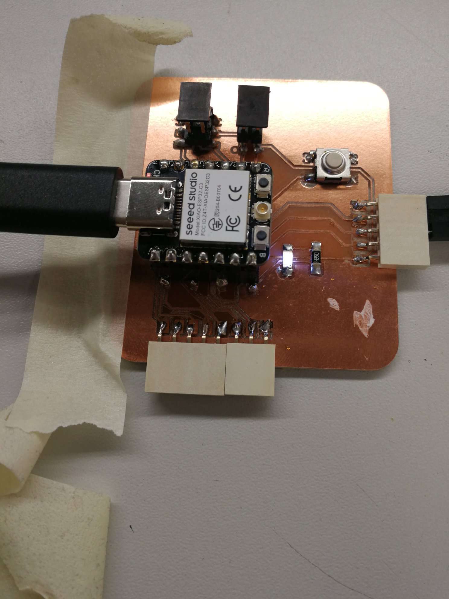
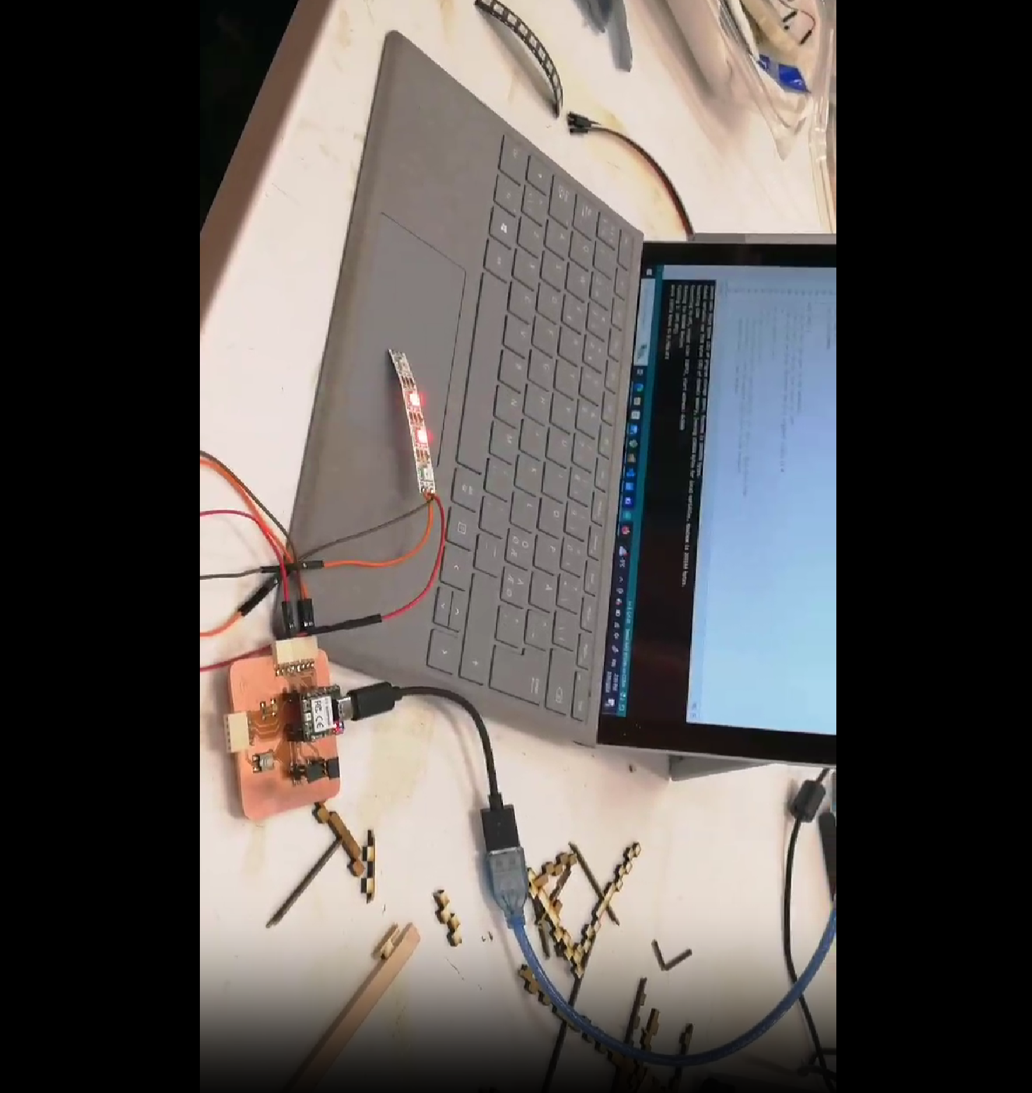
I used the Neopixel led strip to test output operation on my PCB board (shown below) which was manufactured in the “Electronics Production” week.
Setup
NeoPixel LED strip has 3 pins: 1) one for signal (pin connected to red colored wire attached to LED trip in Figure 2) 2) one for 5V (pin connected to orange wire attached to LED trip in Figure 2) 3) one for GND (pin connected to brown colored wire attached to LED trip in Figure 2)
5V pin and GND pin are connected to sockets on PinHeader on the PCB which are connected 5V and GND of Xiao RP2040 on the PCB espectively. Signal pin is connected to a socket in PinHeader on the PCB which is connected to D1 pin of Xiao RP2040 MCU. MCU sends the command to the NeoPixel LED strip via D1 pin.
5V, GND and D1 pins on Xiao RP2040 can be seen in Figure 19 on Week 04: Embedded Programming’s webpage.
Code
I used the same code which was used during my group work. The original code was taken from Aakseli Uulina’s Fab Academy site. During the group work, we wanted to measure different power levels, coressponding to three different colors on neolixel led. I added switch case to get three different power consumption measurement with the same code segment by switching to three different color after every 500 milliseconds. The code had a bug: It was giving three colors but not in sequence. It was later fixed by Aarne Pohjonen by adding “break” in each “switch case block”.
#include <Adafruit_NeoPixel.h>
#define NEOPIXELPIN D1 // Signal pin of Neo Pixel connected to D1 pin of Xiao RP2040 MCU on the PCB
#define NUMPIXELS 3 //Amount of NeoPixels
Adafruit_NeoPixel pixels(NUMPIXELS, NEOPIXELPIN, NEO_RGB + NEO_KHZ800);
#define DELAYVAL 500 // Time (in milliseconds) to pause between loop

void setup() {
  pixels.begin();
  Serial.begin(9600);
}

void loop() {
int bl;
int R=0;
int G=0;
int B=255;
for(bl=0;bl<=2;bl++){
  switch(bl){
    case 0:
        R=255;
        G=0;
        B=0;
        pixels.clear();
        pixels.setPixelColor(2, pixels.Color(R, G, B)); //Nice blue color
        pixels.show(); // Send the updated pixel colors to the hardware.
        pixels.setPixelColor(1, pixels.Color(R, G, B)); // Nice yellow color
        pixels.show();
        pixels.setPixelColor(0, pixels.Color(R, G, B)); // Nice yellow color
        pixels.show();
        Serial.println(bl);
        delay(DELAYVAL);
        break;

    case 1:
        R=0;
        G=255;
        B=0;
        pixels.clear();
        pixels.setPixelColor(2, pixels.Color(R, G, B)); // Nice blue color
        pixels.show(); // Send the updated pixel colors to the hardware.
        pixels.setPixelColor(1, pixels.Color(R, G, B)); // Nice yellow color
        pixels.show();
        Serial.println(bl);
        delay(DELAYVAL); // wait between
        break;
    case 2:
        R=0;
        G=0;
        B=255;
        pixels.clear();
        pixels.setPixelColor(2, pixels.Color(R, G, B)); // Nice blue color
        pixels.show(); // Send the updated pixel colors to the hardware.
        Serial.println(bl);
        delay(DELAYVAL); // wait between
        break;

  }
  //bl++;
}
}
Demo
Controlling Servo Motor
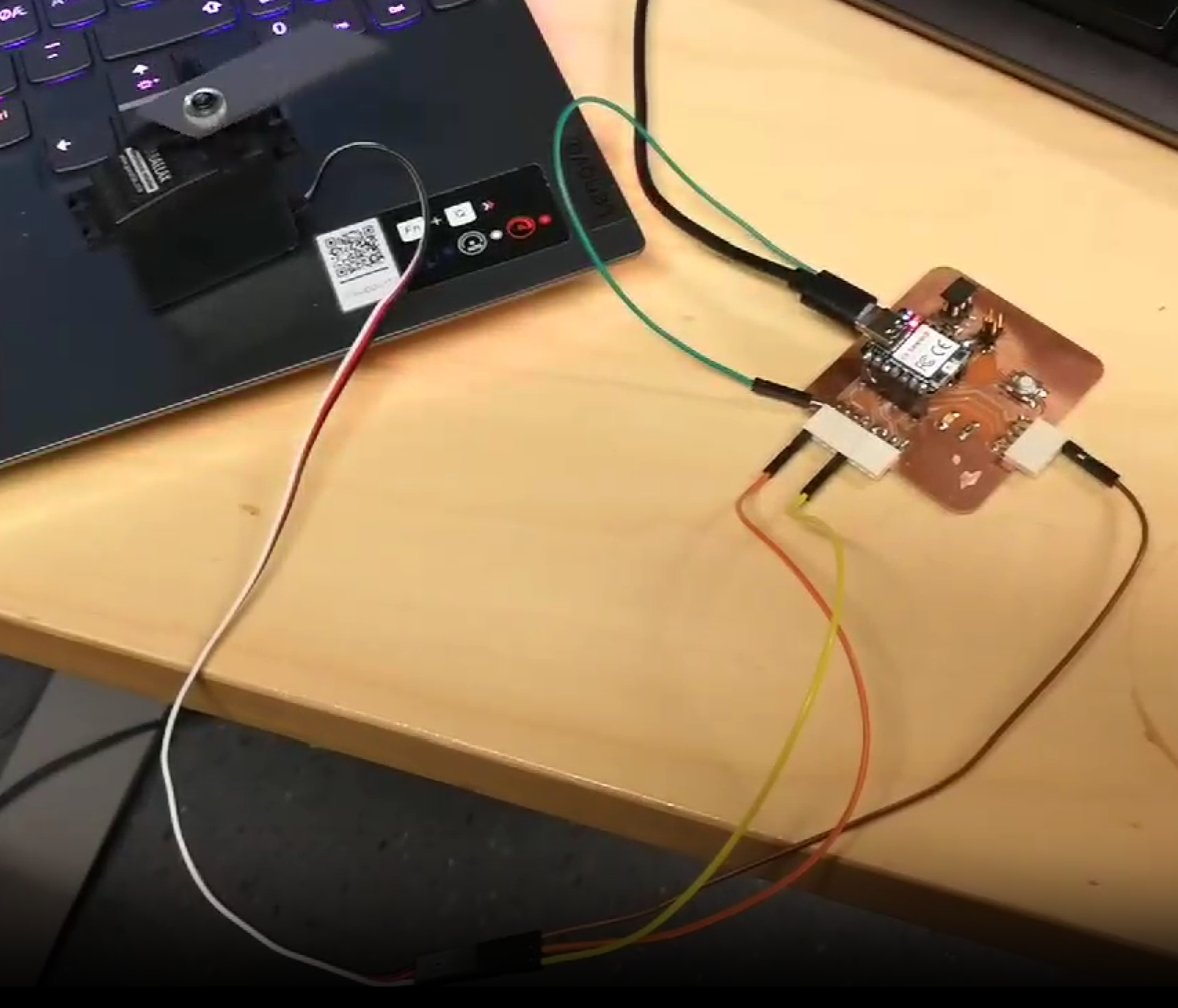
I did this experiment one week later. To demonstrate output operation, I controlled movement of Servo motor with the PCB board. Adruino Servo Library needs to be installed first by following instructions mentioned in Embedded Programming week. Servo’s signal pin is connected to Seeed Xiao RP2040 via D1 pin. Two other pins are 3V (for power) and GND.
Setup
Servo has 3 pins: 1) one for signal (pin connected to white colored wire attached to LED trip in Figure 2) 2) one for Power (pin connected to red wire attached to LED trip in Figure 3) 3) one for GND (pin connected to black colored wire attached to Servo in Figure 3)
Power and GND pin are connected to sockets on PinHeader on the PCB which are connected 5V and GND of Xiao RP2040 on the PCB espectively. Signal pin is connected to a socket in PinHeader on the PCB which is connected to D1 pin of Xiao RP2040 MCU. MCU sends the command to the Servo motor via D1 pin.
Servo is reccommended to be connected to 3V. Weeks later, I realized I had connected to the 5V. Though it worked since the experiment was done for only a minute, but it can damage the Servo if such connection lasts for longer period.
Code
The code allows rotation of servo motor by 180 degree in both direction. The code can be found by following: File-> Examples-> Servo-> Sweep.
/* Sweep
 by BARRAGAN <http://barraganstudio.com>
 This example code is in the public domain.

 modified 8 Nov 2013
 by Scott Fitzgerald
 https://www.arduino.cc/en/Tutorial/LibraryExamples/Sweep
*/

#include <Servo.h>
Servo myservo;  // create servo object to control a servo
// twelve servo objects can be created on most boards

int pos = 0;    // variable to store the servo position

void setup() {
  myservo.attach(D1);  // attaches the servo on pin D1 to the servo object
}

void loop() {
  for(;;){
  for (pos = 0; pos <= 180; pos += 1) { // goes from 0 degrees to 180 degrees
    // in steps of 1 degree
    myservo.write(pos);              // tell servo to go to position in variable 'pos'
    delay(15);                       // waits 15 ms for the servo to reach the position
  }
  for (pos = 180; pos >= 0; pos -= 1) { // goes from 180 degrees to 0 degrees
    myservo.write(pos);              // tell servo to go to position in variable 'pos'
    delay(15);                       // waits 15 ms for the servo to reach the position
  }
  }
}
Demo Video
Note: Because of poor soldering, power pins of Seeed Xiao RP2040 didn’t see to be attached to the board after experiment with neopixel board. So, I used an external green wire to connect the power pin of Seeed Xiao RP2040 to the board.