3. Computer controlled cutting
This week I worked on computer-controlled cutting via a laser cutting machine and a vinyl machine. During the group work, we examined how to take kerf into account during laser cutting. Kerf is excess material burned next to the line so that notches can fit within each other and hold tight to support the structure.
Reflection on group work
During laser cutting, we examined the followings:
-
the focus of the laser cutter by setting different offsets, i.e. how cutting happens when the Z-axis is set too high, or low (aka. vertical distance between cutting material and the laser cutter). An offset of 1 mm does not impact cutting much, however, if the offset is set to 4mm or high, it does not cut the material.
-
Effect of cutting speed: If the cutting speed was too high, it didn’t cut the material.
-
Power of the laser cutting: If the power was too low, it didn’t cut the material.
Both cutting speed and power are co-dependent, i.e. if the cutting speed is low, it won’t cut the material well if the power is quite low. The Contrast in laser engraving is also impacted by these two factors.
- Effect of Dots per Inch (DPI): Higher DPI leads to more contrast in engravings.
All these were examined with and without kerf taking into account to understand the importance of kerf. I also had to account for the right kerf by trial and error in my assignment.
Laser cutting
For this assignment, I decided to make kit for assembling a tower. Kit can be used to make single story tower, or double story tower.
OpenSCAD Program
“Computer cutting instructions for design patterns” are written in OpenSCAD.
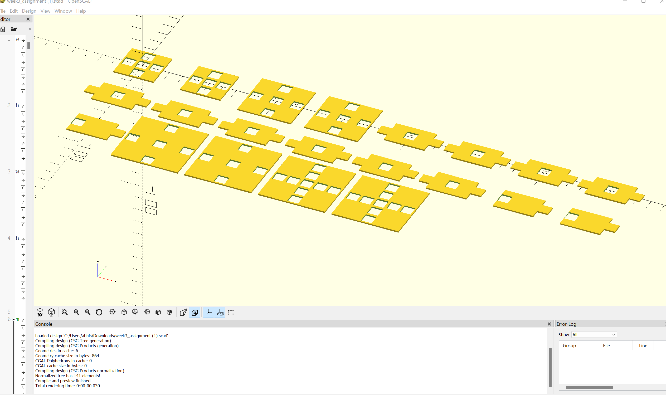 Figure 1: Design Patterns in OpenSCAD
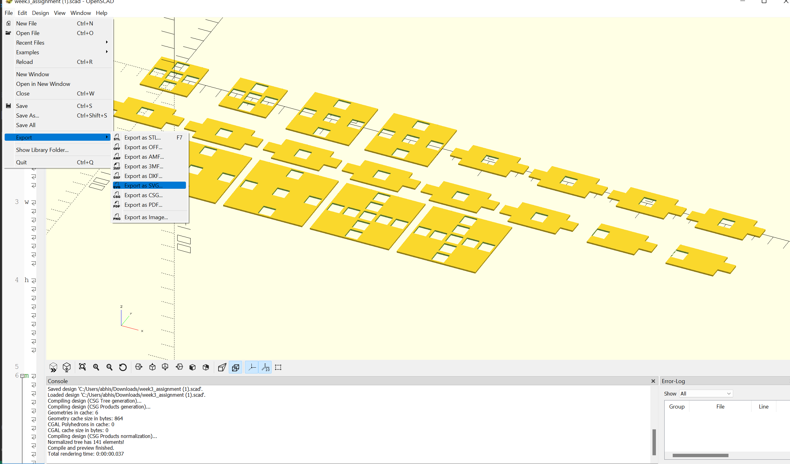 Figure 2: Exporting the OpenSCAD program as SVG file. File-> Export-> Export as SVG…
The OpenSCAD program can be downloaded from here.
The SVG file exported from OpenSCAD program can be downloaded from here.
Processing in InkScape and sending print command to Laser Cutting Machine
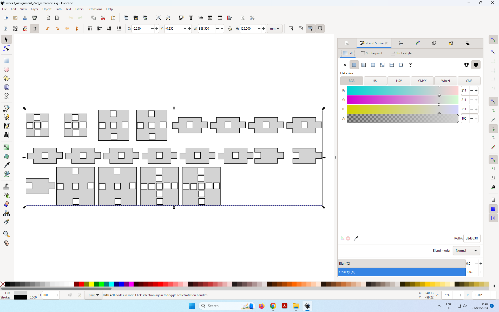 Figure 3: Opening SVG file in InkScape
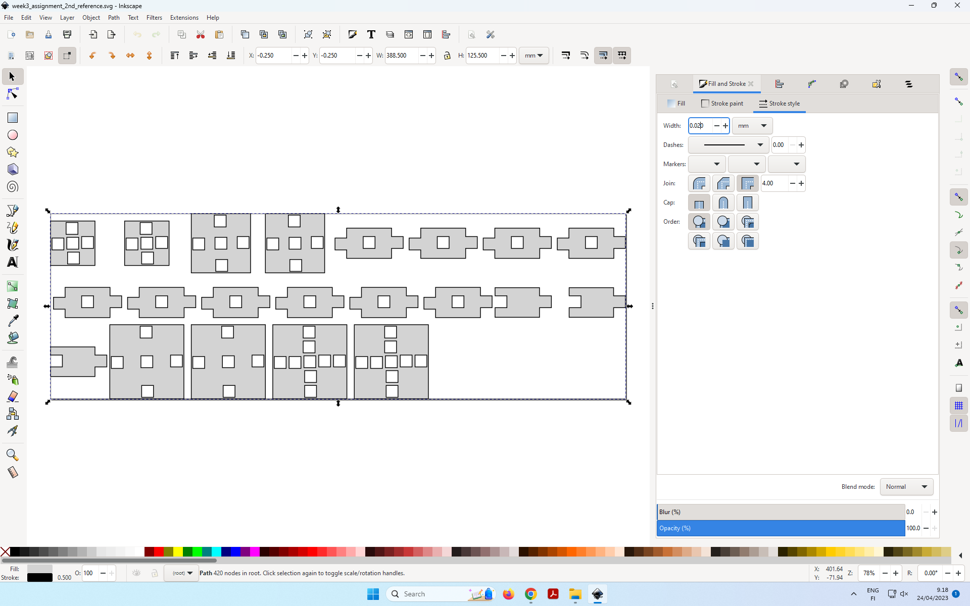 Figure 4: Setting Stroke Width to 0.02 mm.
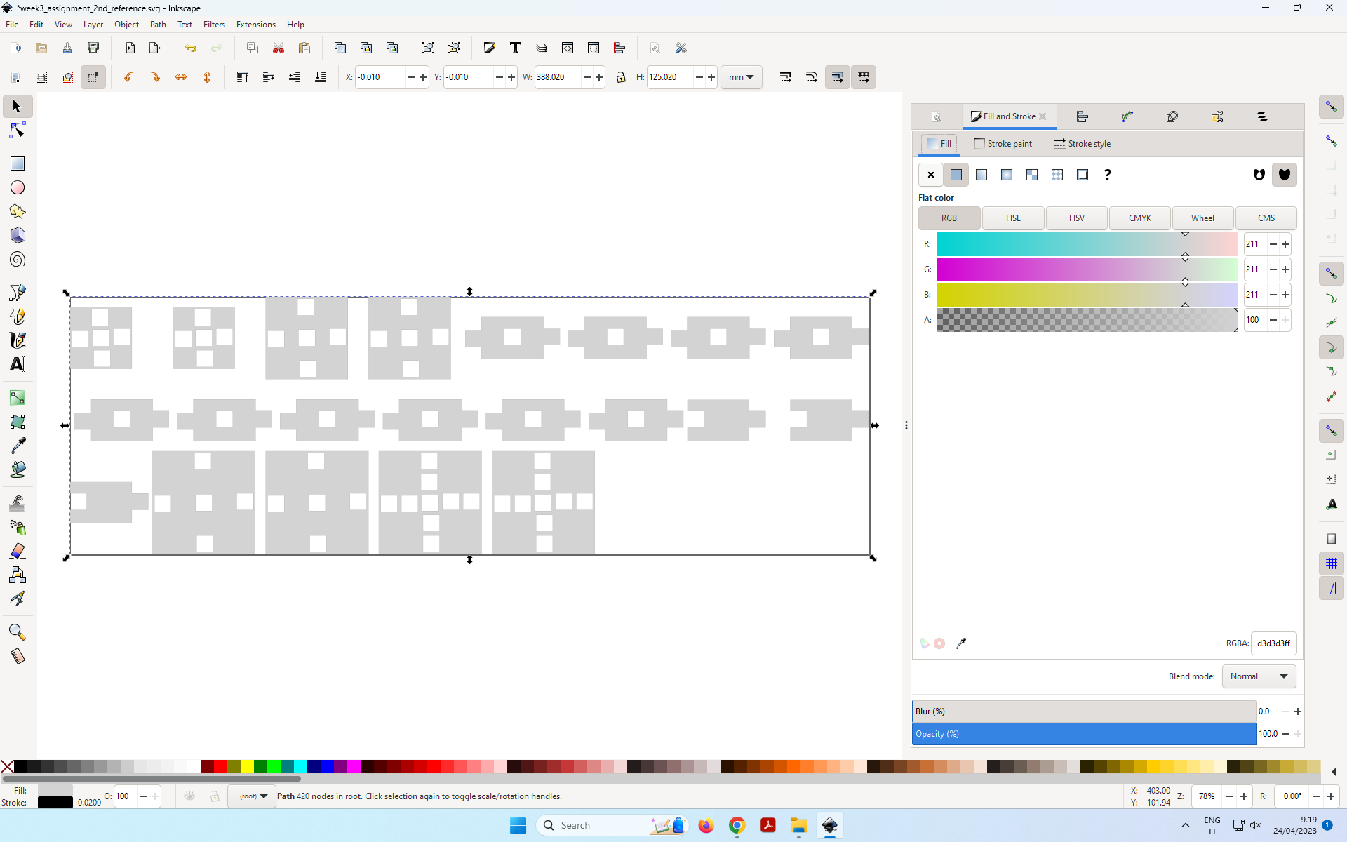 Figure 5. Settig no Fill by clicking on “x” option, since there is no engraving .
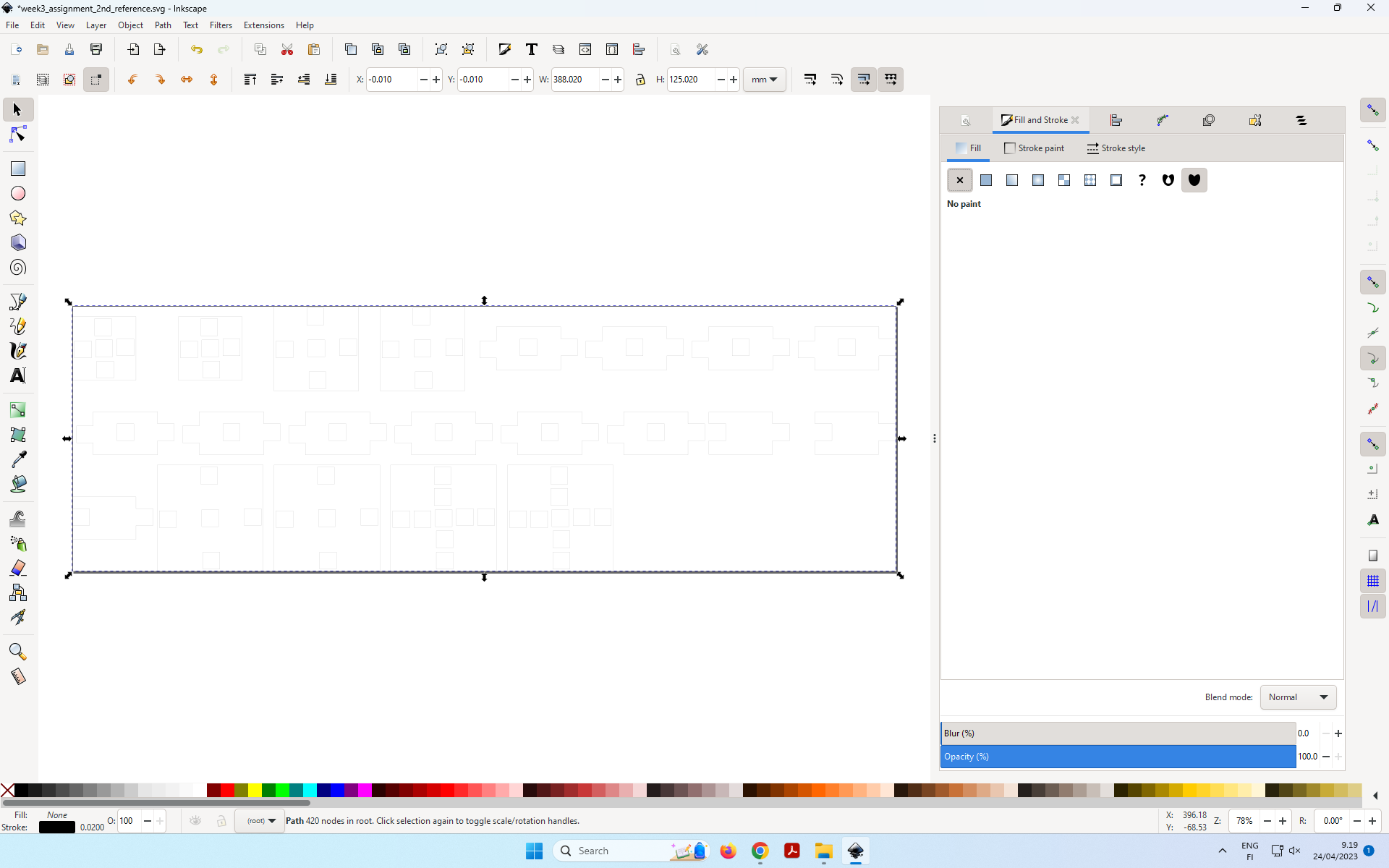 Figure 6: After no fill.
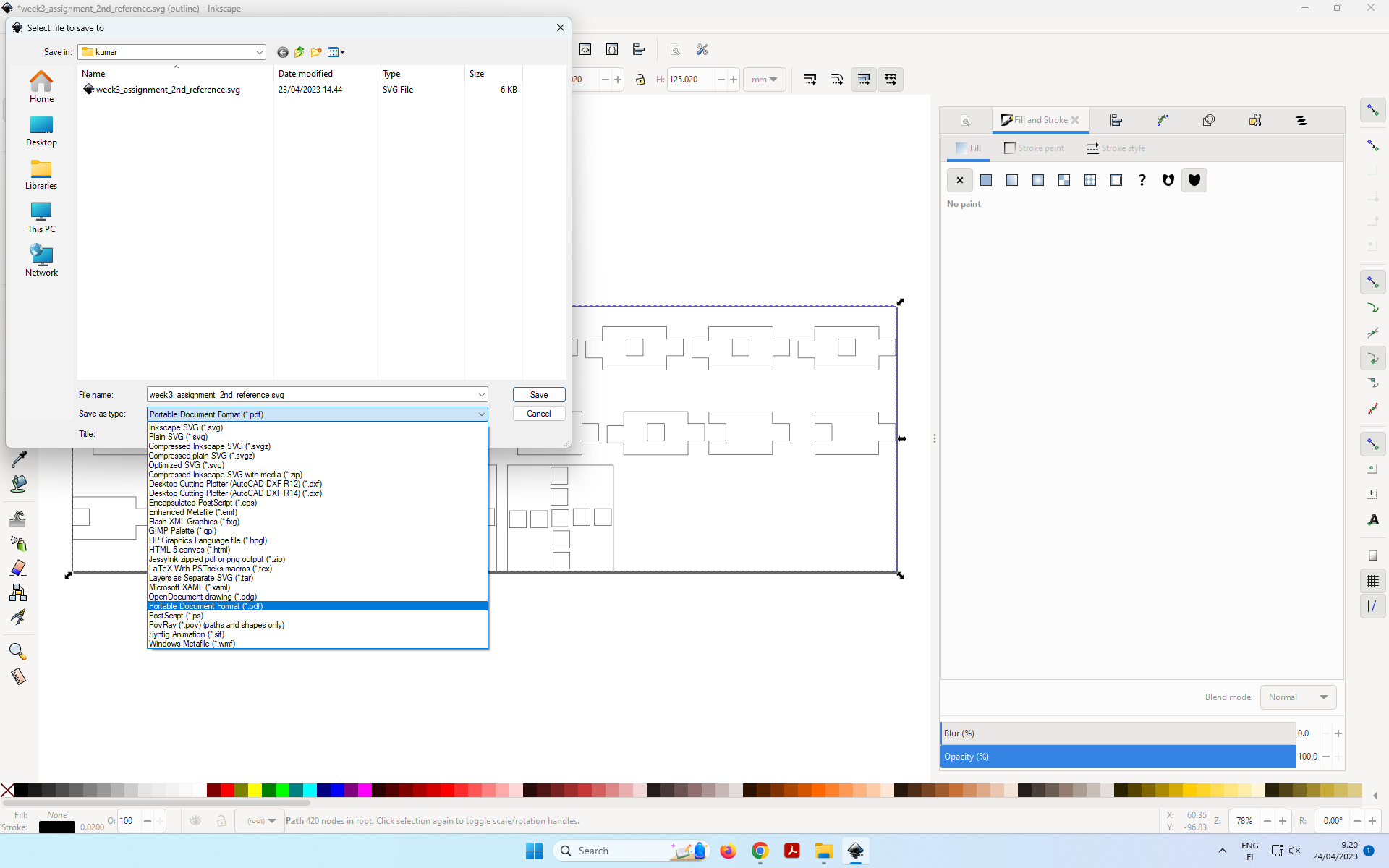 Figure 7: Exportig file as PDF: File->Save as->Save as Type PDF.
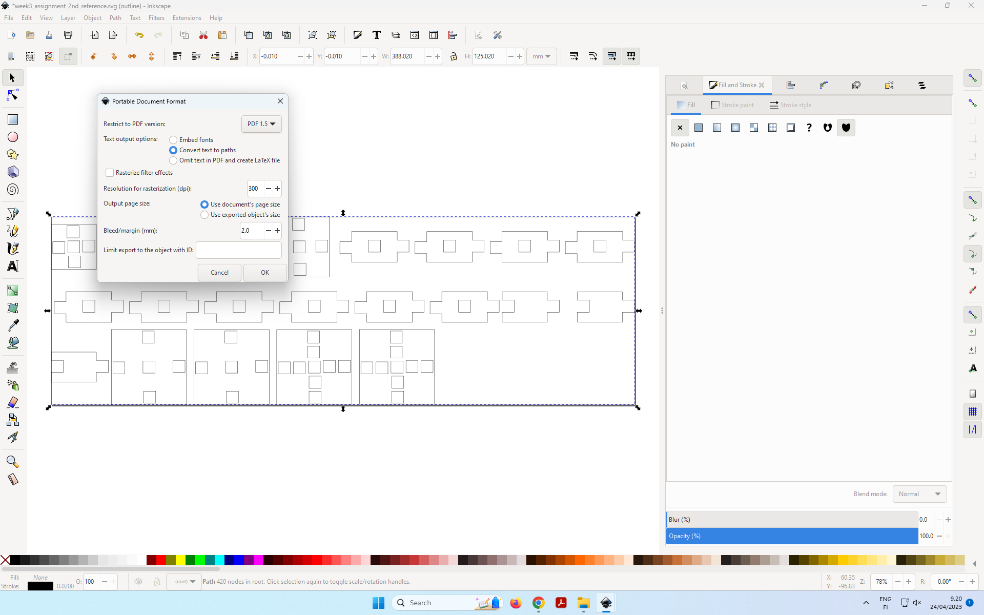 Figure 8: Choose default setting, and OK.
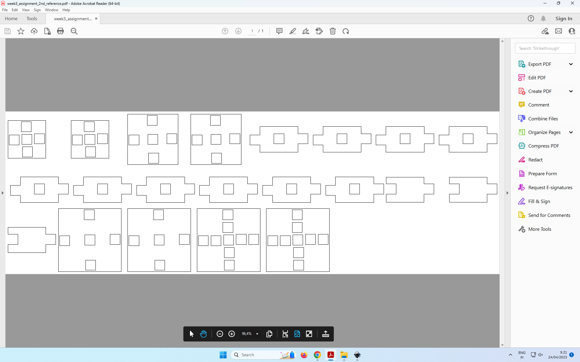 Figure 9: Open exported PDF.
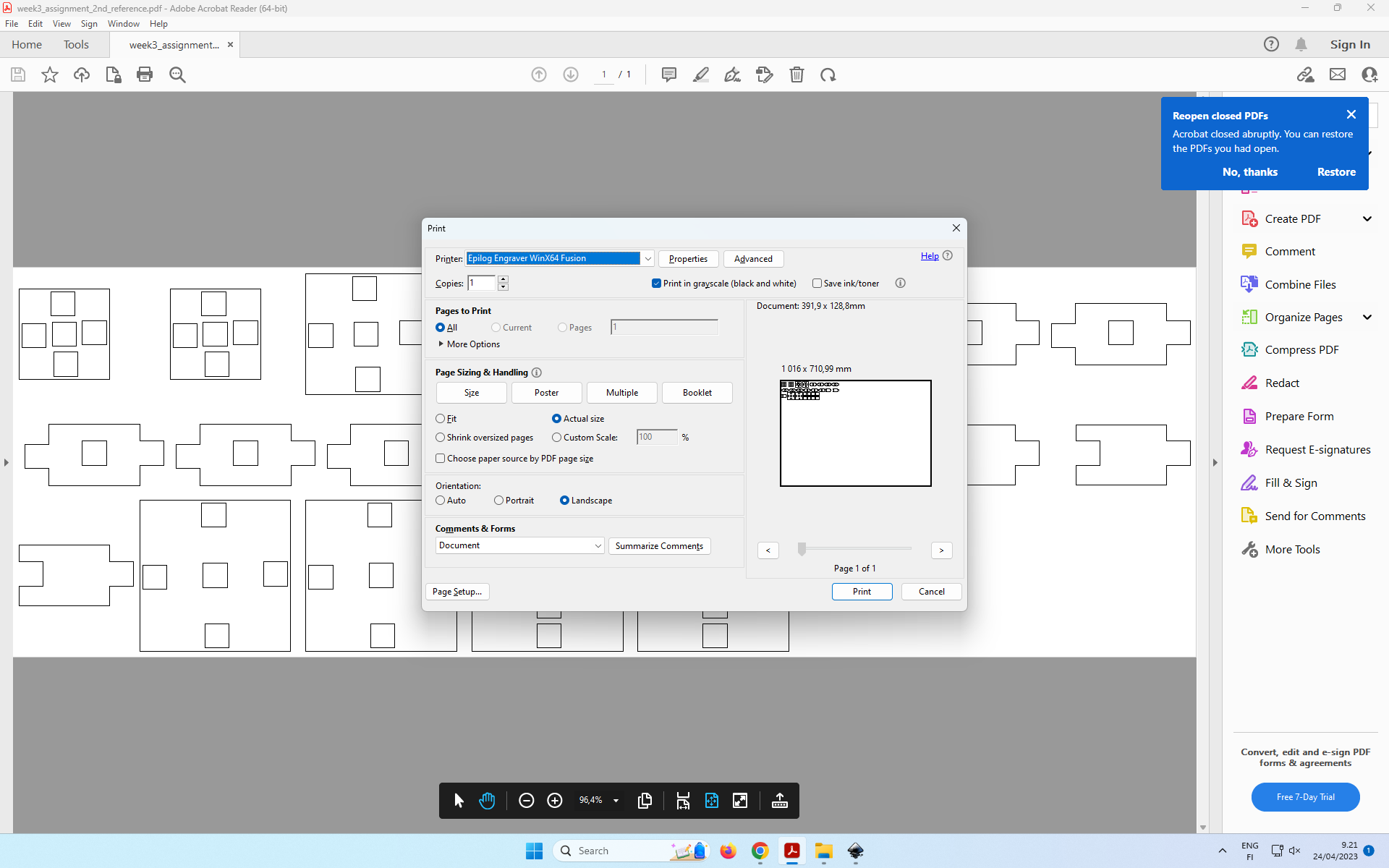 Figure 10: Print the pdf by pressing Ctrl + P, or File -> Print. In Print Window, Click Properties Tab.
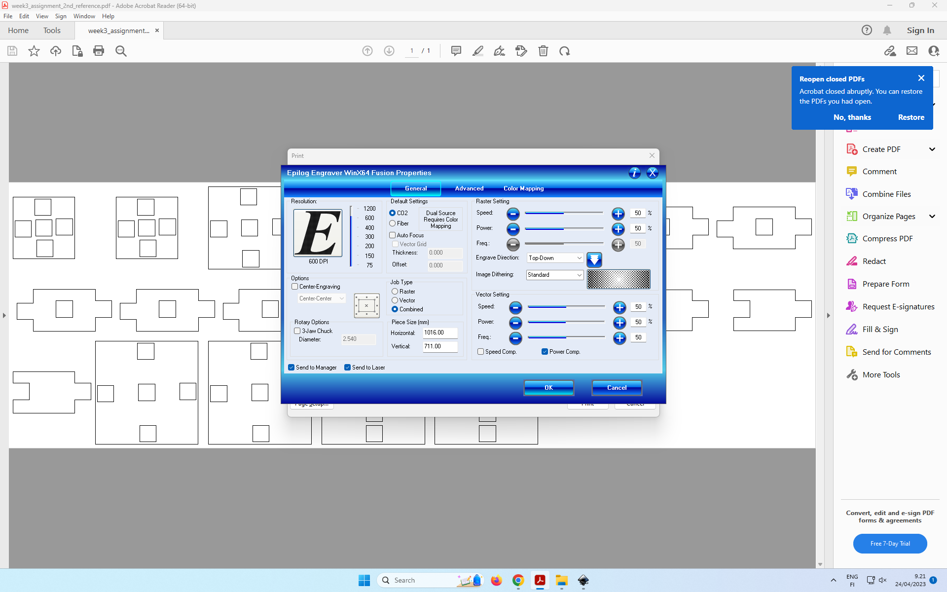 Figure 11: In Proprties Window, Click Advanced Tab.
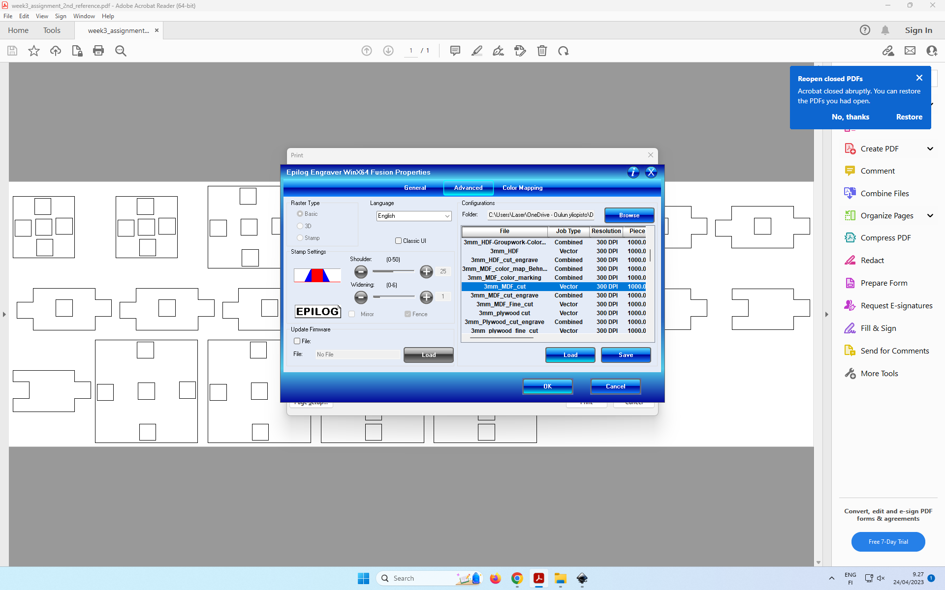 Figure 12: Select “3mm MDF Cut” profile and Press Load”.
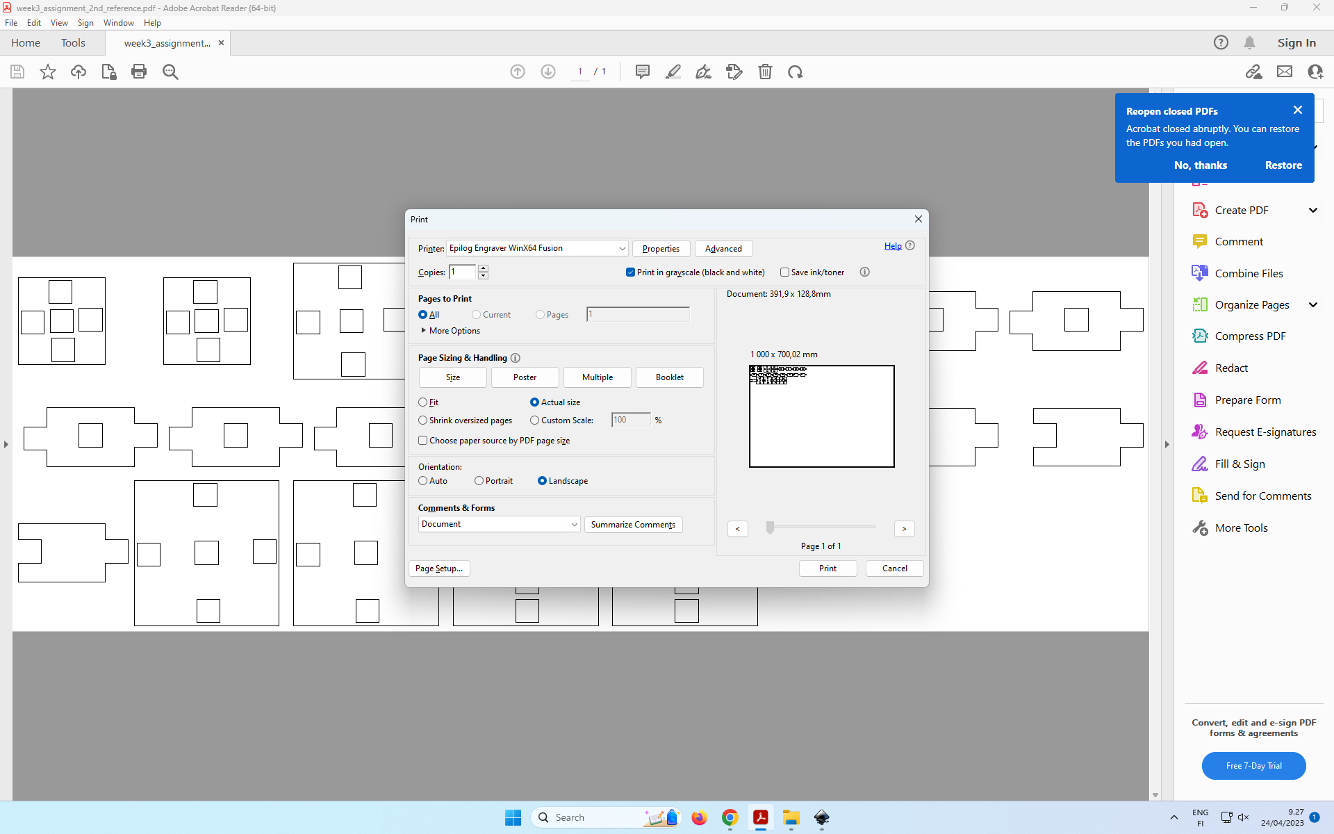 Figure 13: Click OK.
Now the instruction has been sent to the laser cutting machine.
Setting origin of laser cuttting and initiating the job
Figure 14 shows the control panel of the laser cutting machine. For my purposes, three control buttons (Jog, Focus, Job) and joystick are very important.
- Place the cutting material inside the laser cutting machine.
- Use “Jog”, to place the intial (X, Y) point of the laser cutting machine (aka. origin point).
- Use “Focus”, to determine the vertical distace between the material and laser stroke. (aka. setting Z axis)
- Use “Job” is to select the relevent job, and Then press “Go” to begin the cutting.
Joystick is used to select different buttons, move the position of the laser cutter (left and right, up and down). It is used to select the given button on the control panel.
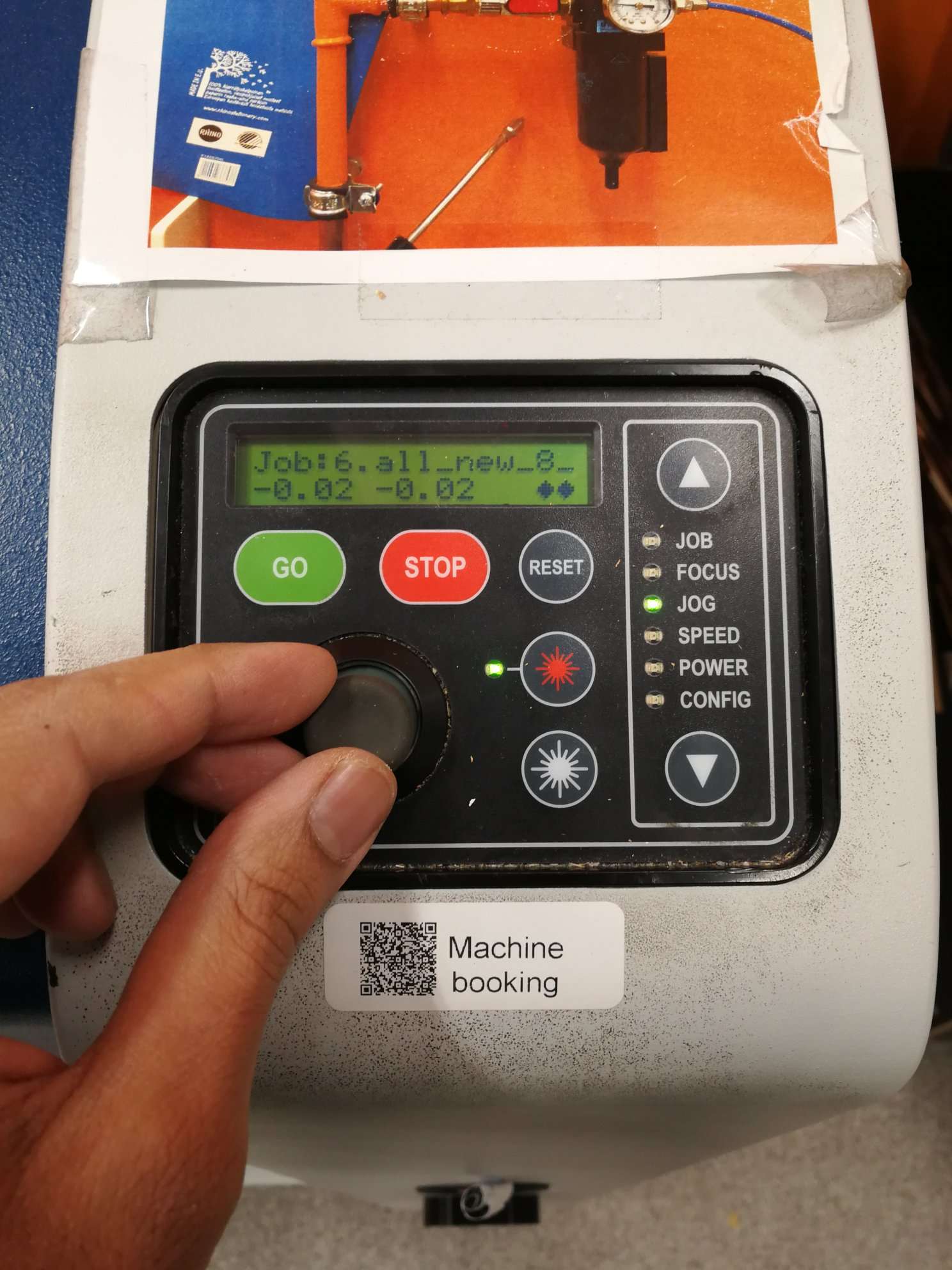 Figure 14: Using “Jog” to place the origin point for the laser cutting.
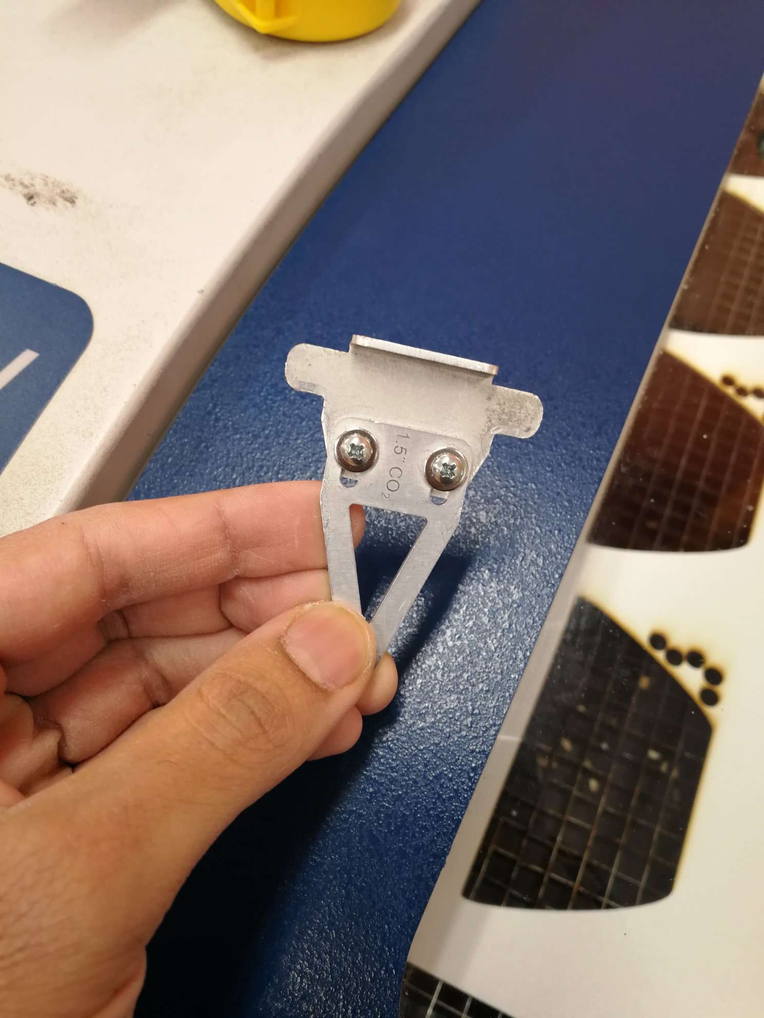 Figure 15. Using this auxuilliary equipment to ensure that laser stroke is above the cutting material by ths distance of this equipment only.
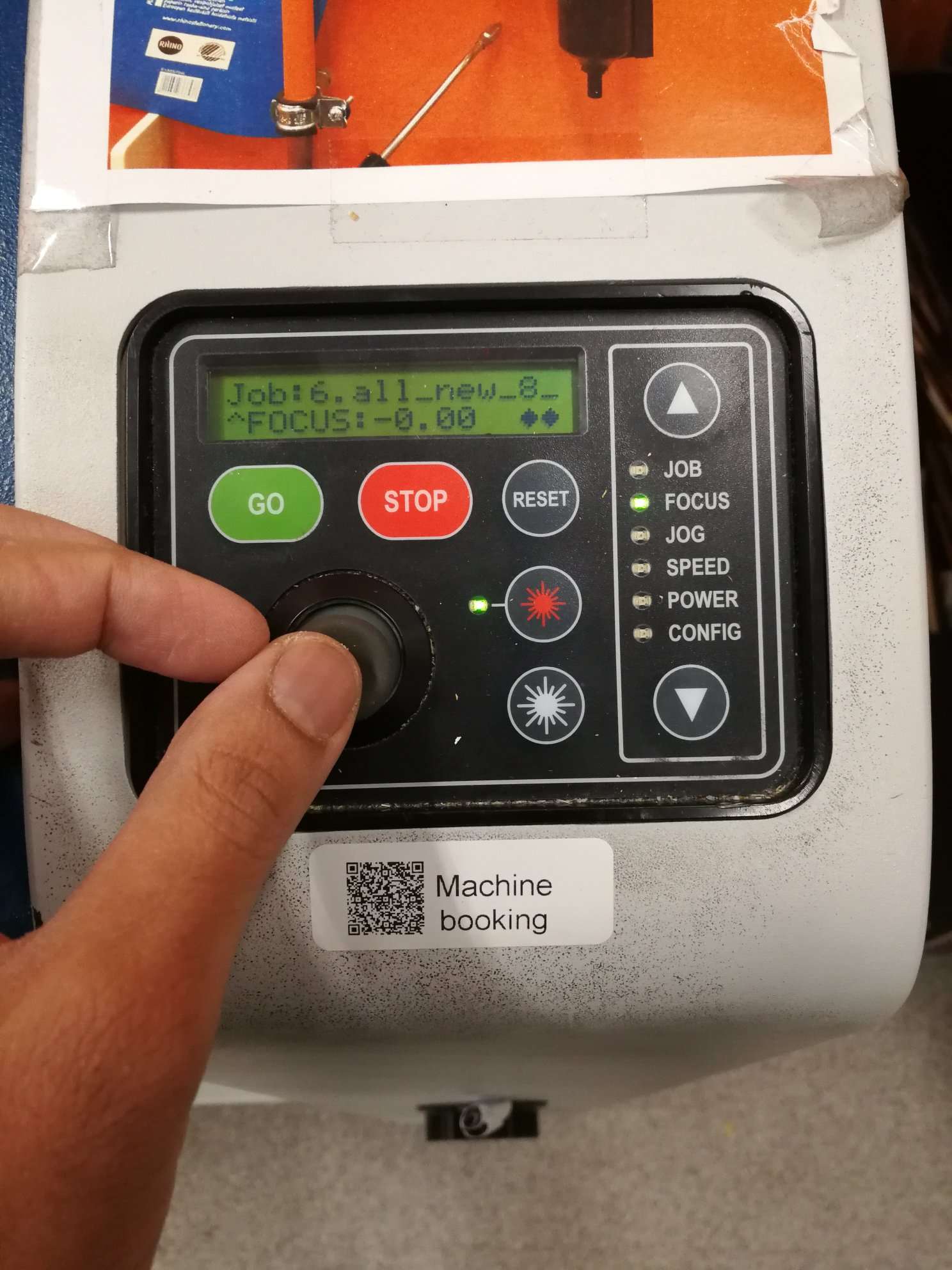 Figure 16: For setting the focus.
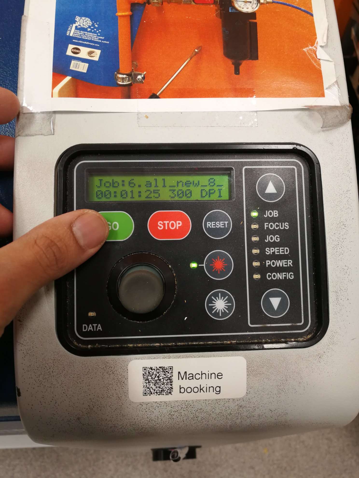 Figure 17: Press “Go” for cutting to begin.
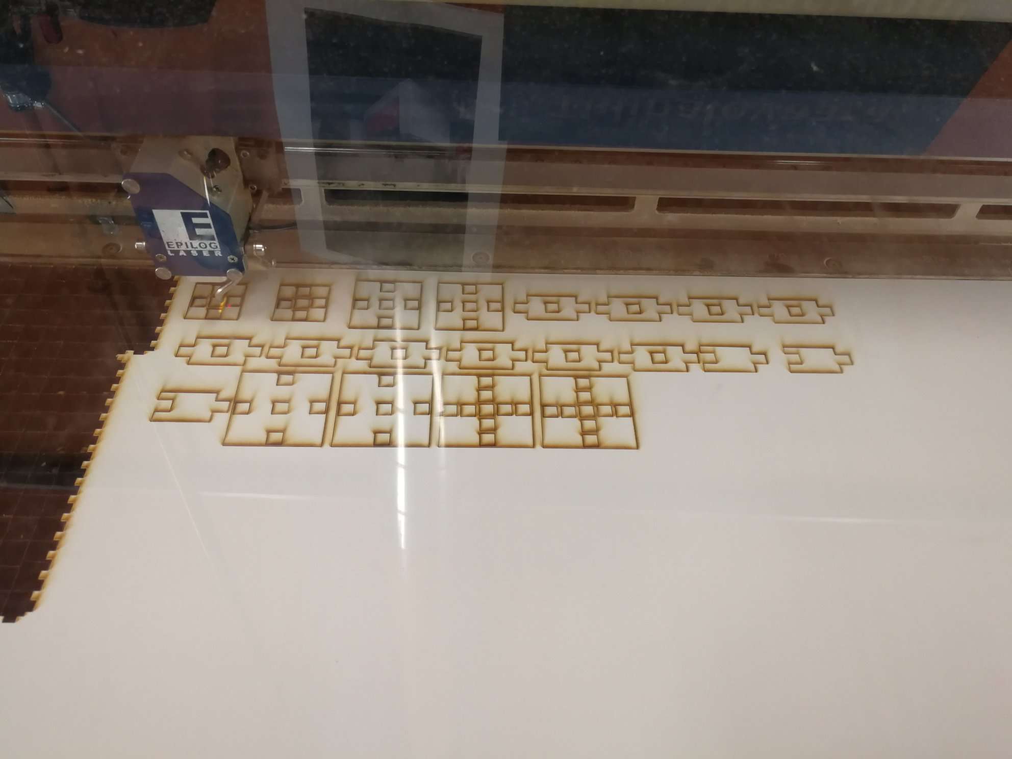 Figure 18: After laser cutting is finished.
Accounting Kerf
The program has three major paramaters: (w_in, h_in, kerf). (w_in, h_in) are for setting width and length of inner notches. I needed to account for kerf by trial and error.
Two other variables (w_out, h_out) are for setting width and length of outer notches, and they automatically set by taking kerf into account. Thus, their values do not need to be provided by the user.
Initially, I had set these values (in mm):
- w_in = 8;
- h_in = 8;
- kerf = 0.1;
//measurements of outer notches automatically set by kerf and measurements of inner notches. - w_out =w_in + kerf; - h_out = h_in + kerf;
However, notches were too loose. Then, I increased kerf to 0.30. It was too big. Then, I converged to these values (kerf being 0.25), which worked out fine:
- w_in = 8;
- h_in = 8;
- kerf = 0.25;
Making a tower
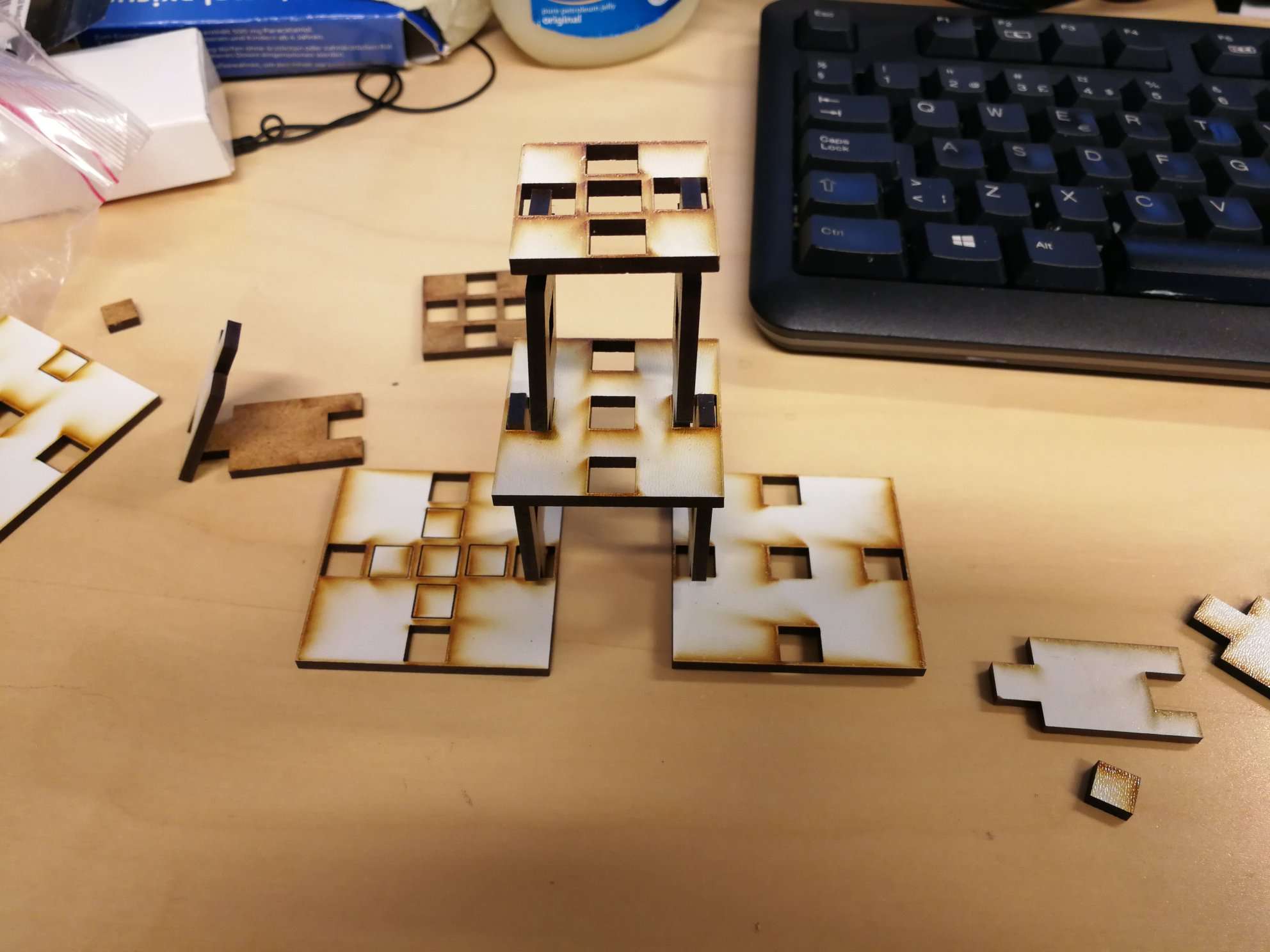 Figure 19: Assembling Tower 1.
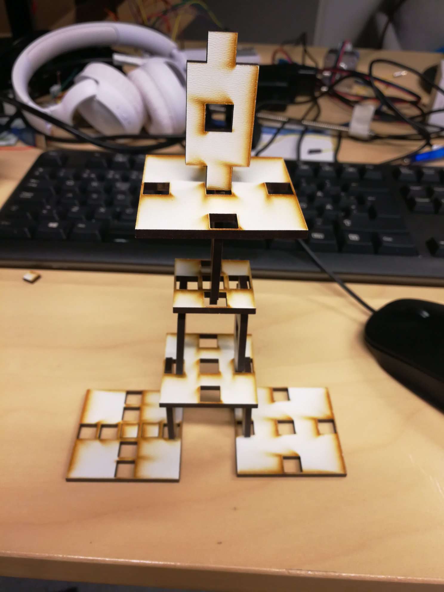 Figure 20: Assembling Tower 2.
Vinyl Cutter
I used the logo of my workplace for this assignment to make a stricker which I could paste on my work laptop.
INTERACTIVE EDGE
CENTER FOR UBIQUITOUS COMPUTING
UNIVERSITY OF OULU
OULU FINLAND
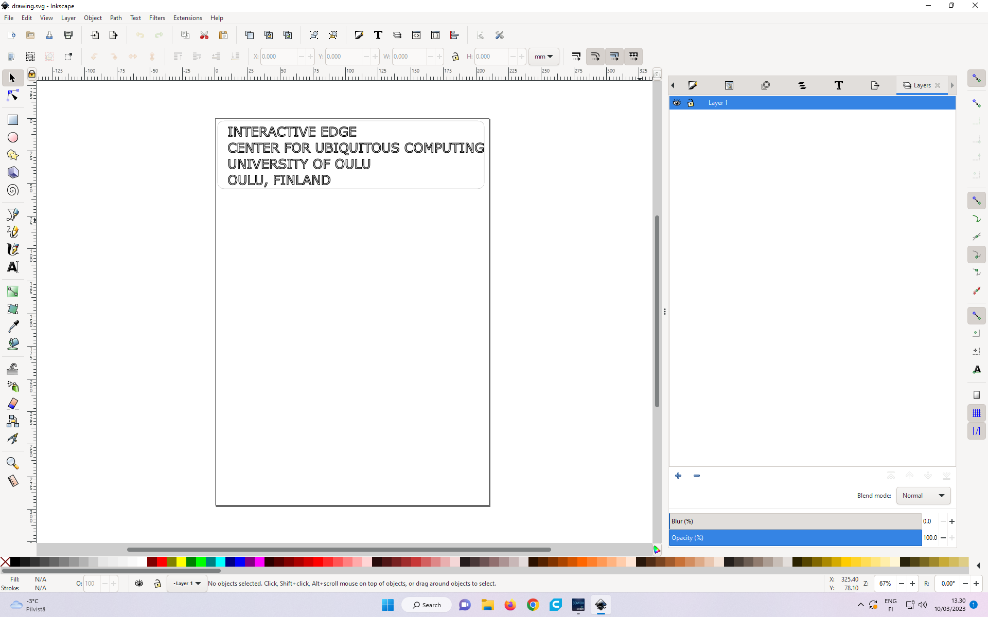 Figure 21: Creating Logo in InkScape
The SVG file with the logo can be downloaded from here.
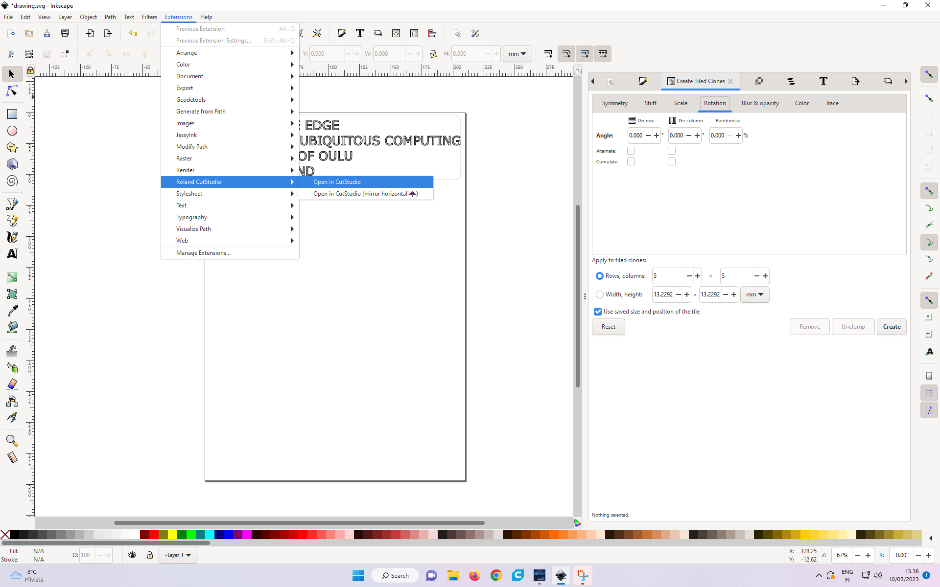 Figure 21: Opening in CutStudio program.
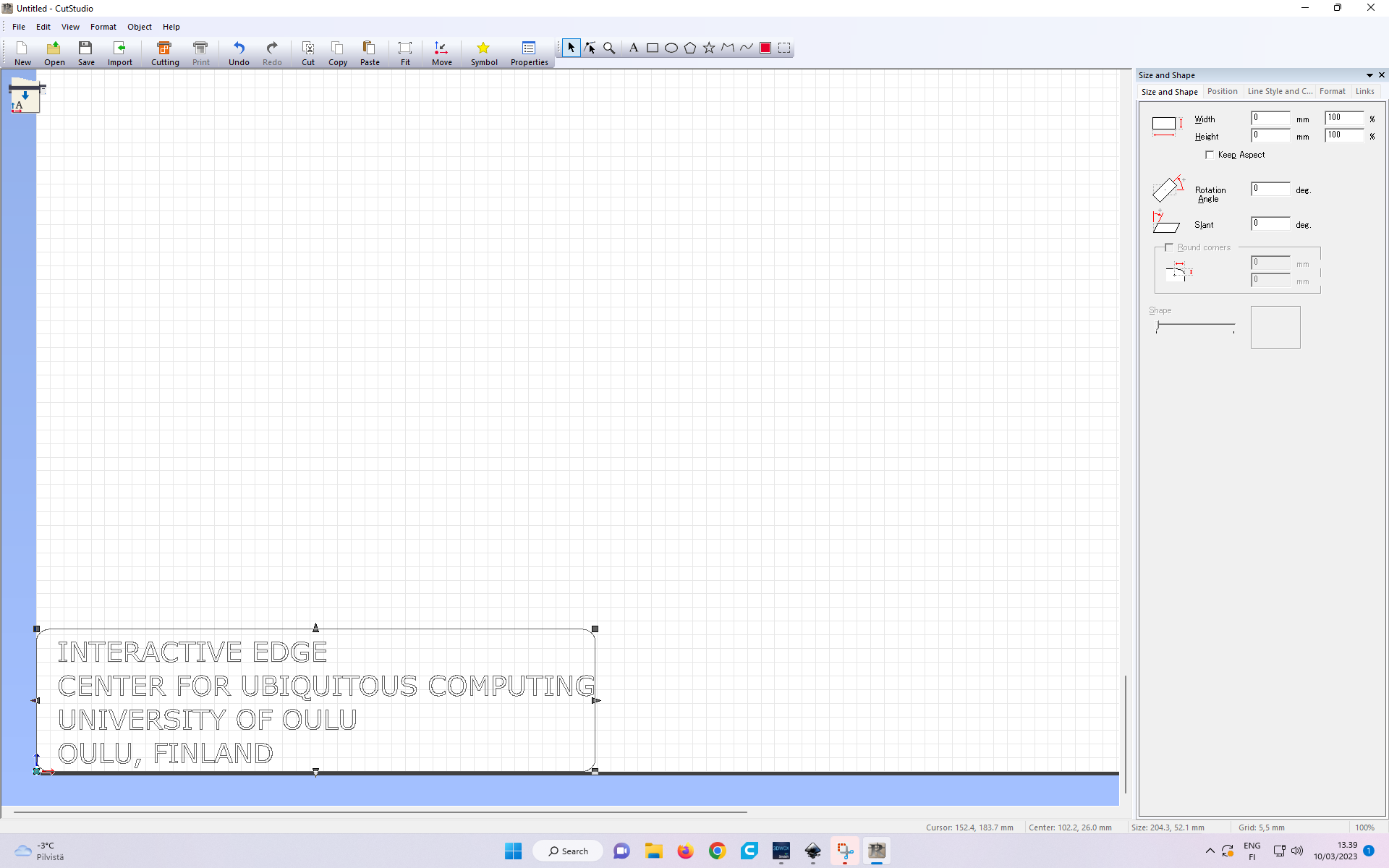 Figure 22 Logo sticker exported in CutStudio program.
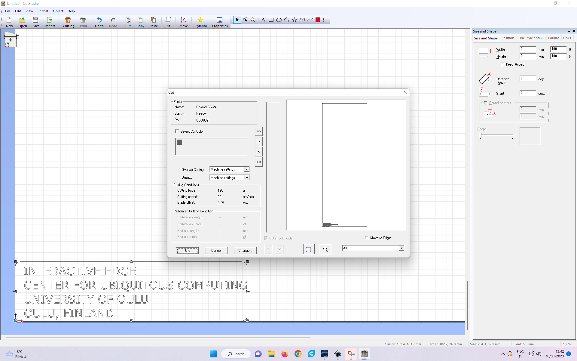 Figure 23: Giving Print Command to create the logo on Roland GS-24 Vinyl Cutter.
The CST file processed by CutStudio which is sent to Vinyl Cutter, can be downloaded from here.
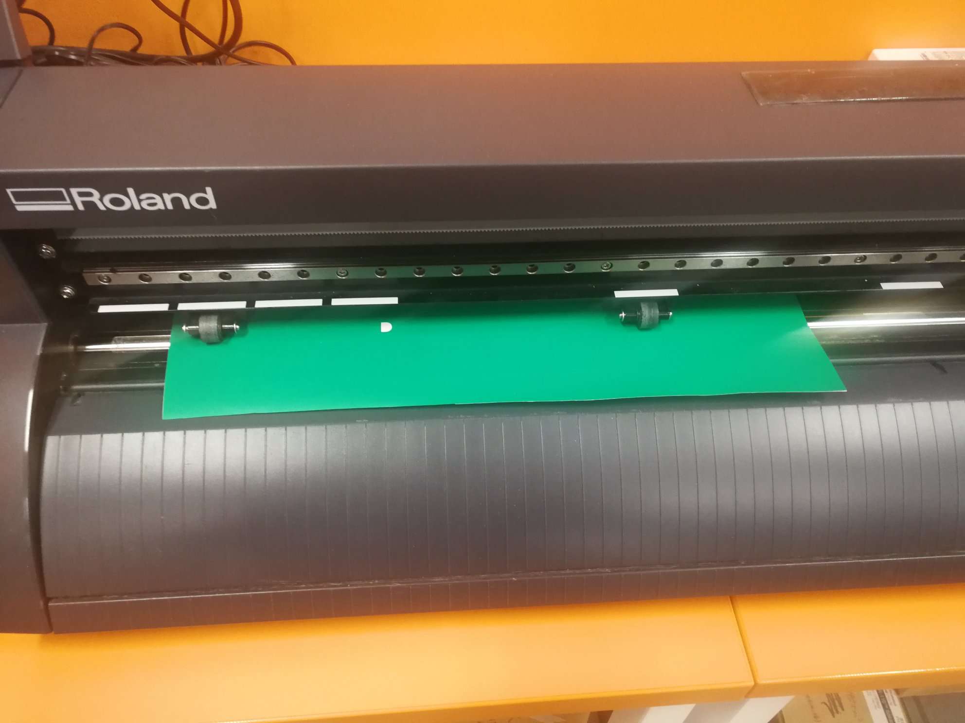 Figure 24: Adjusting the sheet on the Vinyl Cutter, and setting these two rollers.
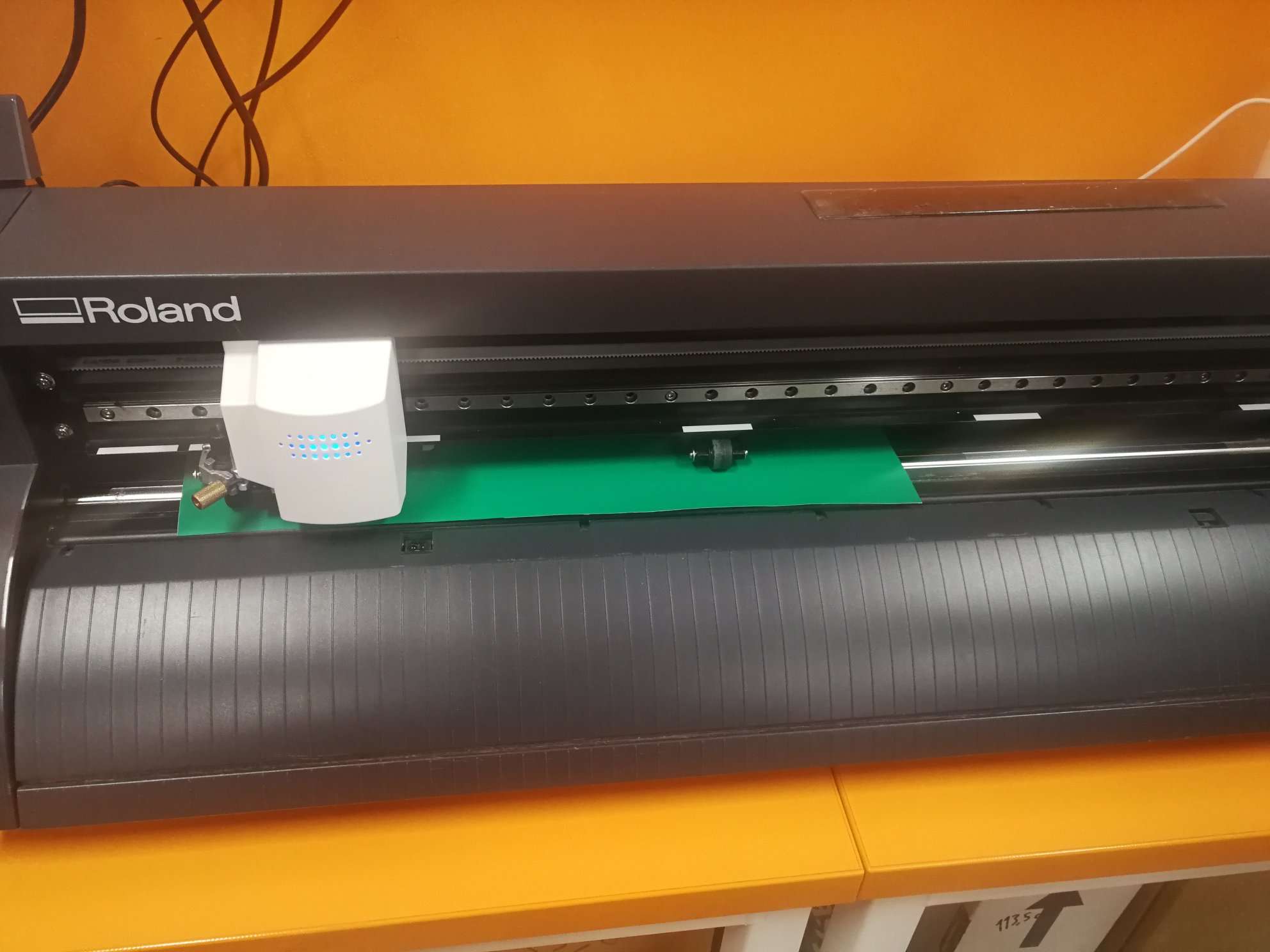 Figure 25: Positioning the Vinyl Cutter’s intial cutting edge/starting point.
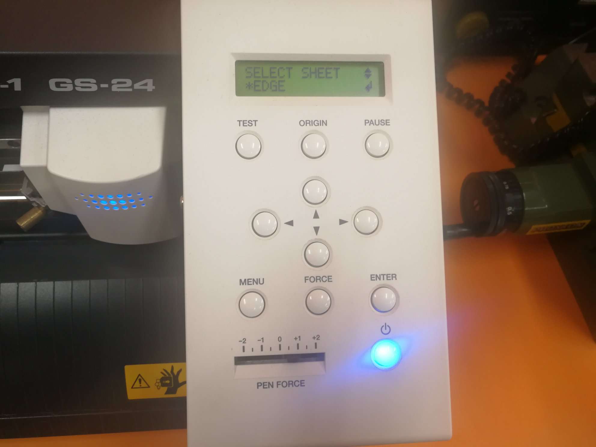 Figure 26: Setting the cutting at the edge.
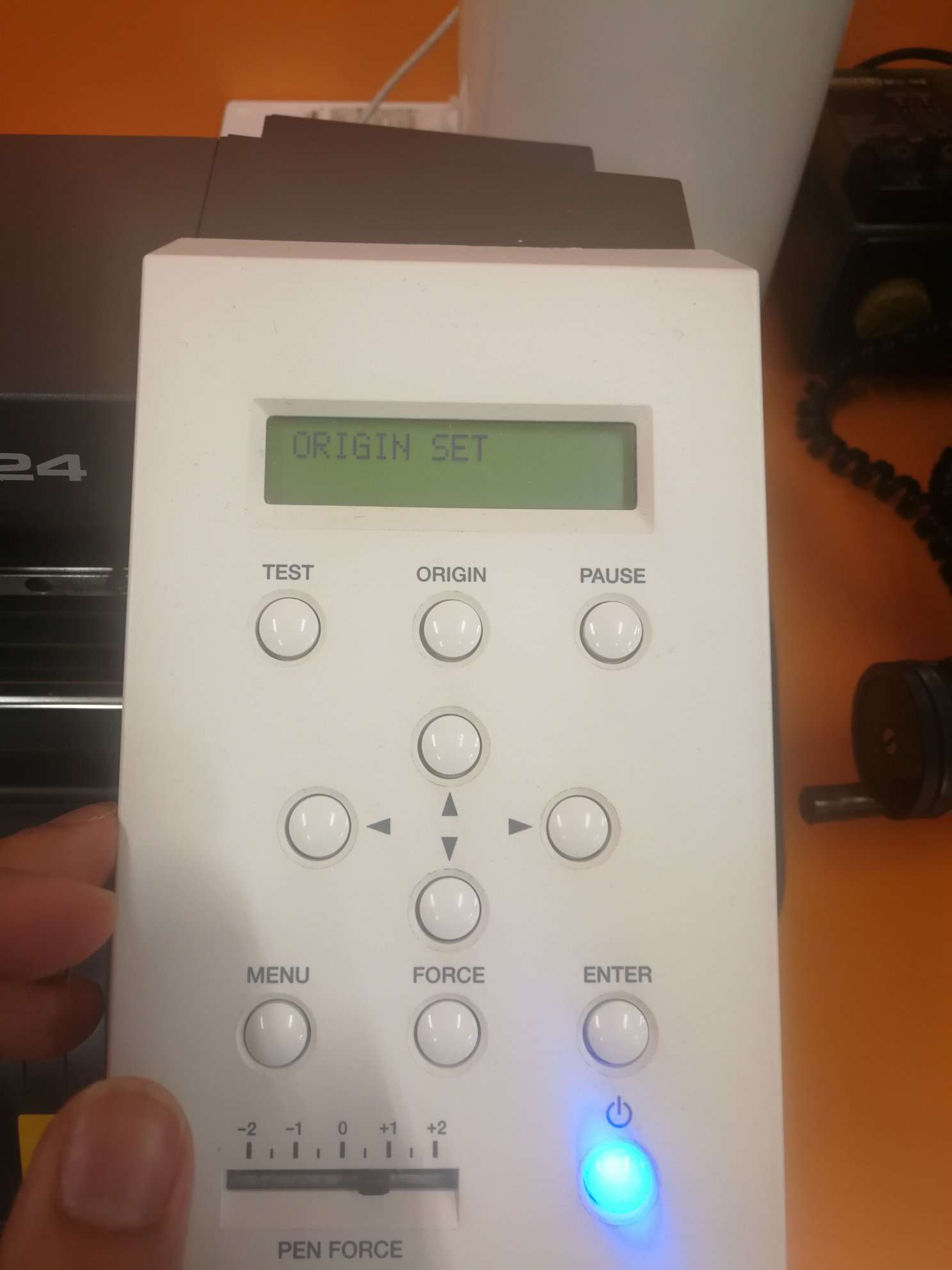 Figure 27: Setting the origin point, then initiating the cut.
After the cut finishes, I carved out all letters manually.
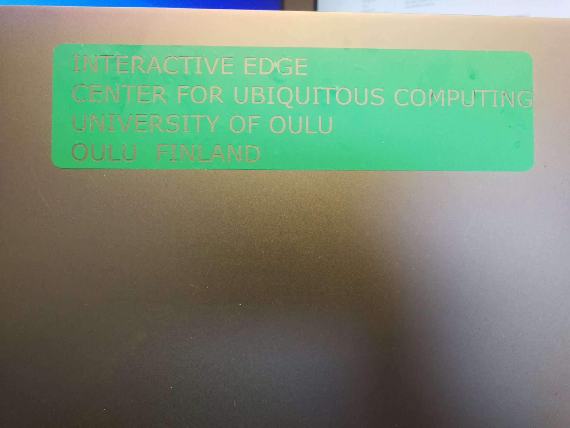 Figure 28: Logo Sticker pasted on the Laptop.