Output Devices
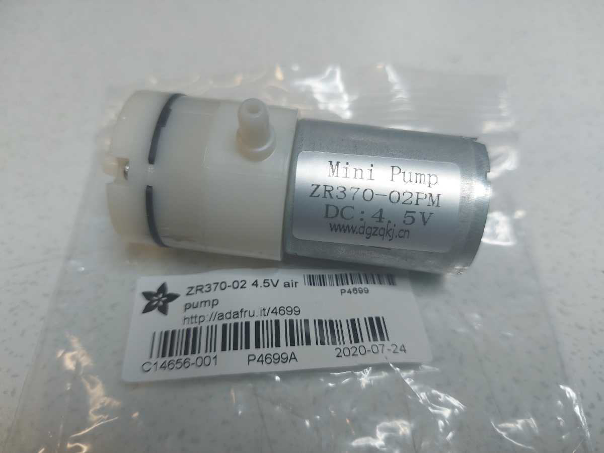
As I would like to further work with inflatables for my final project - I wanted to work with an air pump as an output device. I got an Air Pump and Vacuum DC Motor - 4.5 V and 2.5 LPM from Adafruit with specification available here
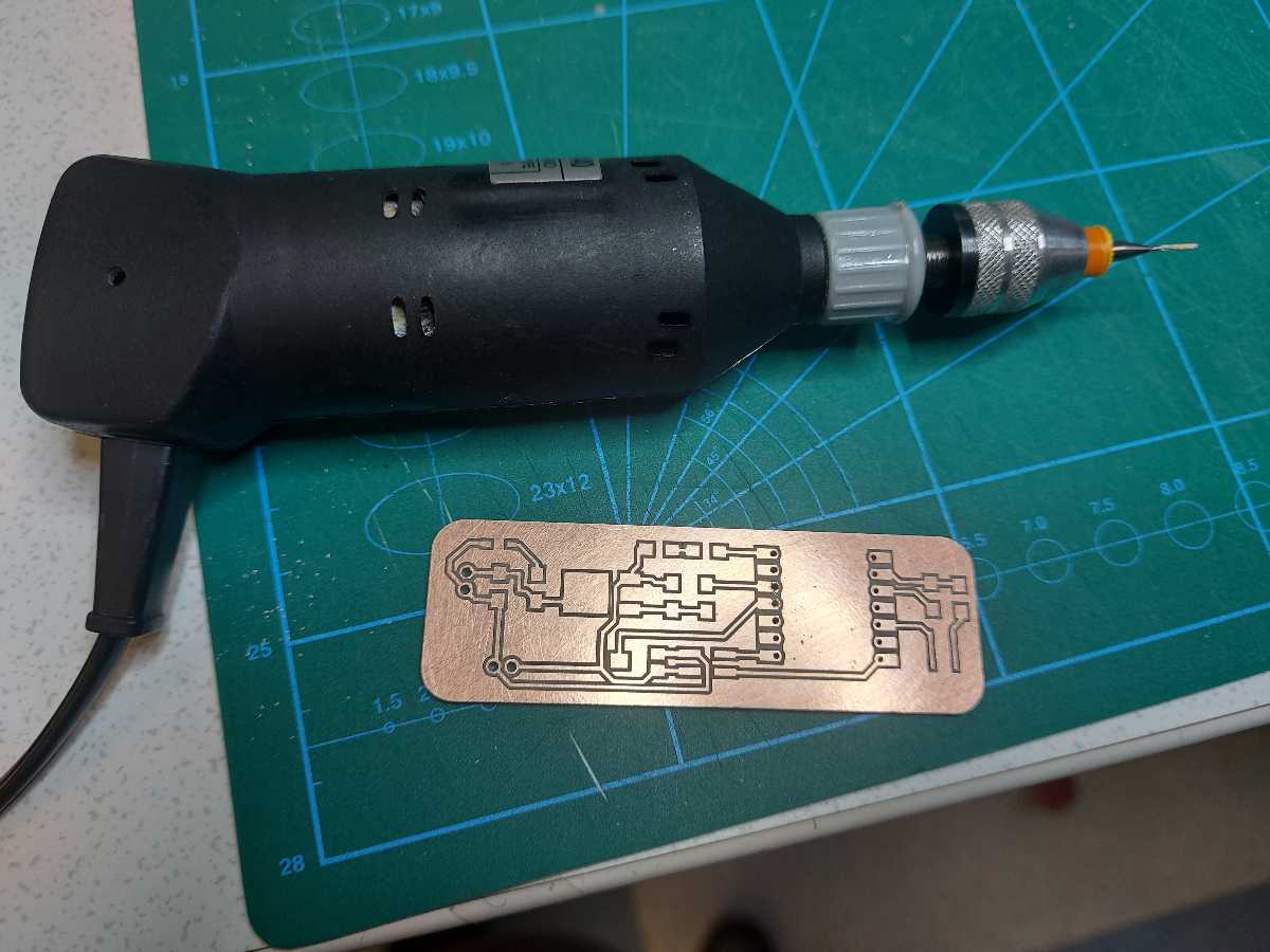
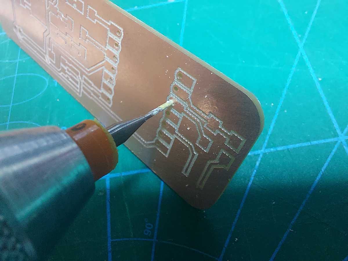
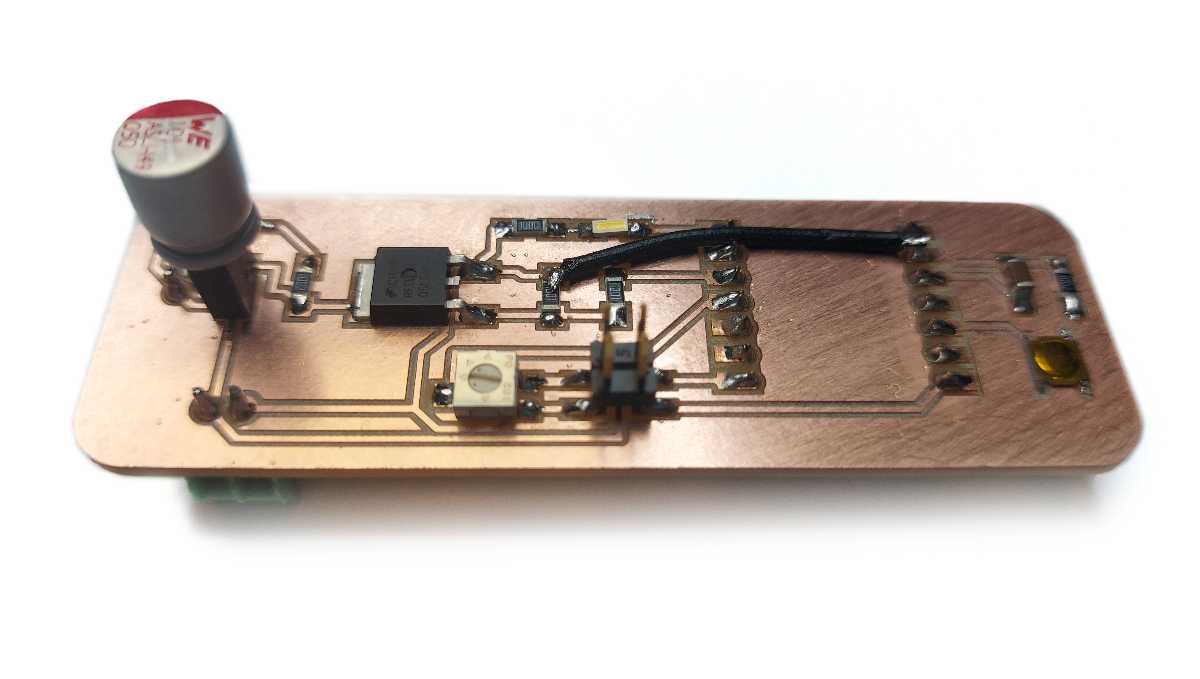
First attempt
Even though, I've set the drilling and cutting depth to 0.1mm more than the actual stock depth, the board was not cut entirely. I needed to break it out of the stock by force. The drill holes were also not deep enough. I used a dremel tool with the same bit installed. I carefully placed the bit in the holes first and locked its position, so it wouldn't move, only then turned the machine on
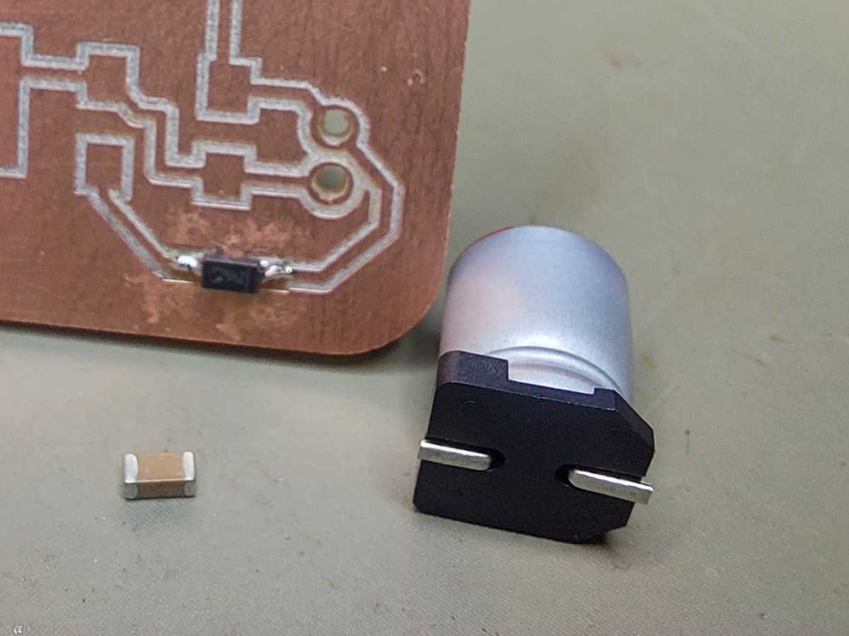
Unaware how much capacitors may vary in size, I used the wrong footprint for the capacitor I thought I needed in the board. So this is the capacitor I designed for and the capacitor I picke,d when actually looked up the right capacity. Obviosuly it wouldn't fit on the small pads, so unwilling to mill yet another board, I soldered on a header and put the capacitor in it, removing the plastic bottom and bending the pins.
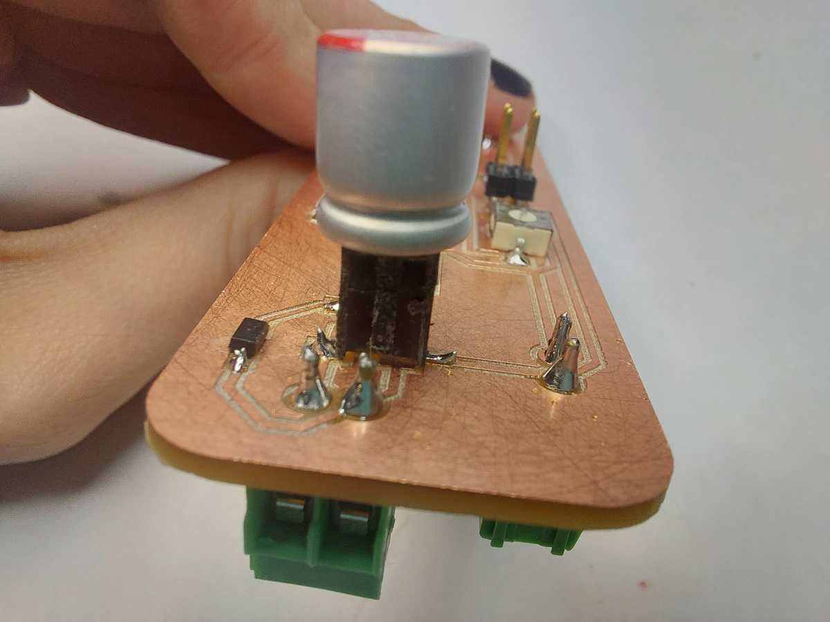
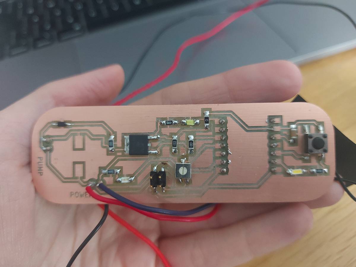
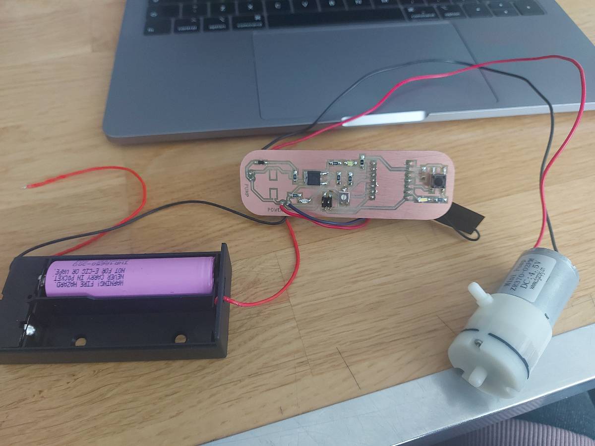
Second attempt
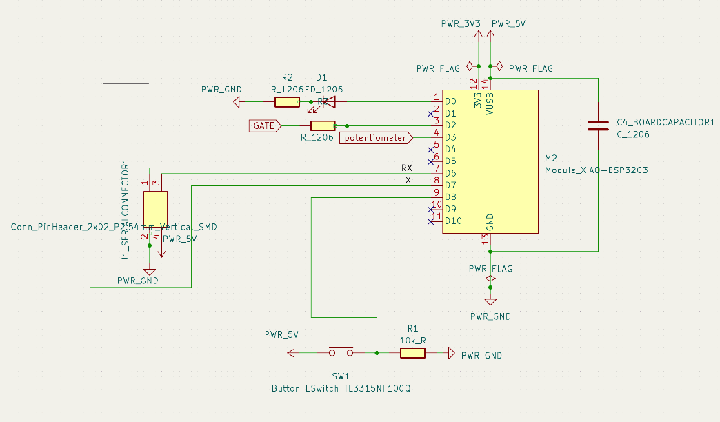
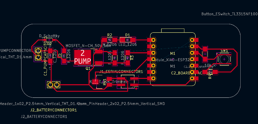
In the second design I fixed and improved the design as pictured>
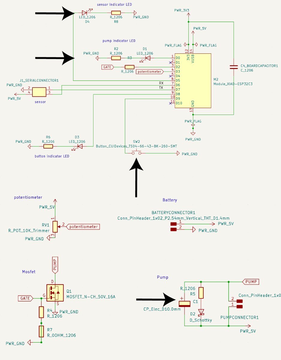
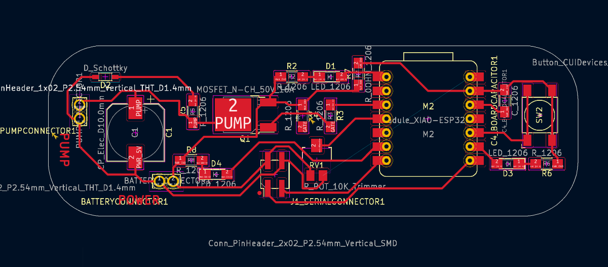
Updates:
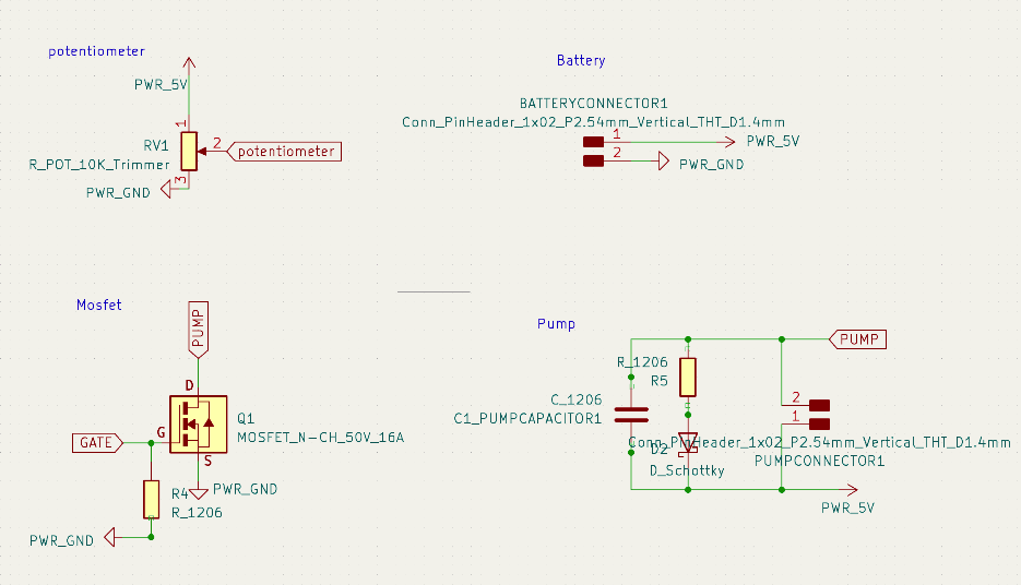
- I changed the footrpint of the pump capacitor from C_1206 to CP_Elec_D10.0mm. As Kris suggested, it wasn't necessary, but I still wanted to have the option in case it turn out to be necessary. I left it unsoldered
- I connected the grounds of both power circuits as should have done before
- I introduced indicator LEDs - one that would when the pump is on and one to map and indicate the sensor values as I had it in the Electronics Production assignment
- I engraved text according to the pins by the screw-in terminals to avoid any mistakes
- I swapped the small copper switch Button_ESwitch_TL3315NF100Q for an actual proper button Button_CUIDevices_TS04-66-43-BK-260-SMT that would be easier to solder and also much easier and convenient to operate
To still improve
- Connect the Xiao power and ground pins to the power supply, to make the board wireless
- Introduce main switch by the power supply that would cut off the power from the whole circuit
- Swap the MOSFET for an H-bridge
- Make a fitting case for the battery and board/some kind of fixture to hold it together
Arduino basic on/off code
int ledPin = D0;
int motPin = D2;
int ledState = 0;
int motState = 0;

void setup() {
  pinMode(ledPin, OUTPUT);
  pinMode(motPin, OUTPUT);
}

void loop() {
  digitalWrite(ledPin, ledState);
  digitalWrite(motPin, motState);
  ledState = !ledState;
  motState = !motState;
  delay(2000);
}