Embedded Programming
Group assignment page
It covers worklflows of programming boards using programmers. We explored programming of an ATtiny412 Hello World and a D11C USB-C Hello World board
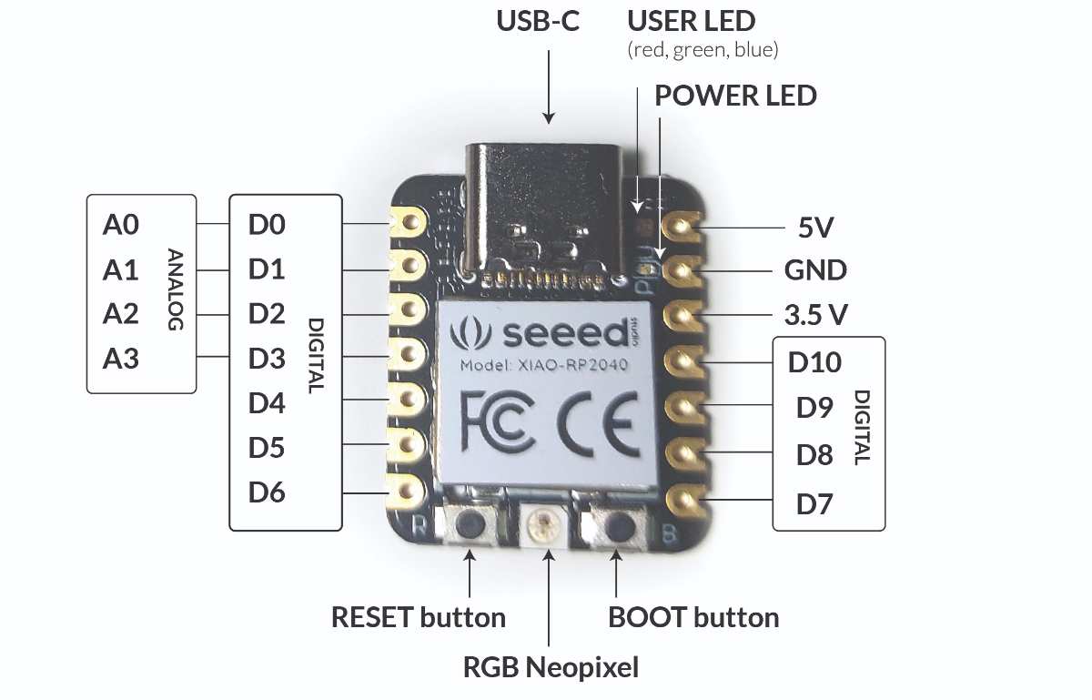
Seeed Studio XIAO RP2040 with Arduino
The full specification of Seeed Studio XIAO RP2040 is available on the manufacturer's site. For getting started with this board, I closely followed the Seeed Studio original instructions
set up and basic blink
- First I long pressed the BOOT button on the board (bottom right) and connected the board to my computer using a USB - c cable
- I opened the Arduino IDE software. In File > Preferences , I found the Additional Boards Manager URLs , clicked on the icon on the right to expand the view and pasted the following:
https://github.com/earlephilhower/arduino-pico/releases/download/global/package_rp2040_index.json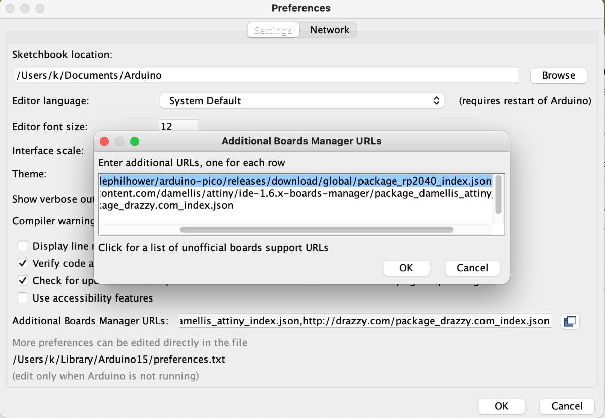
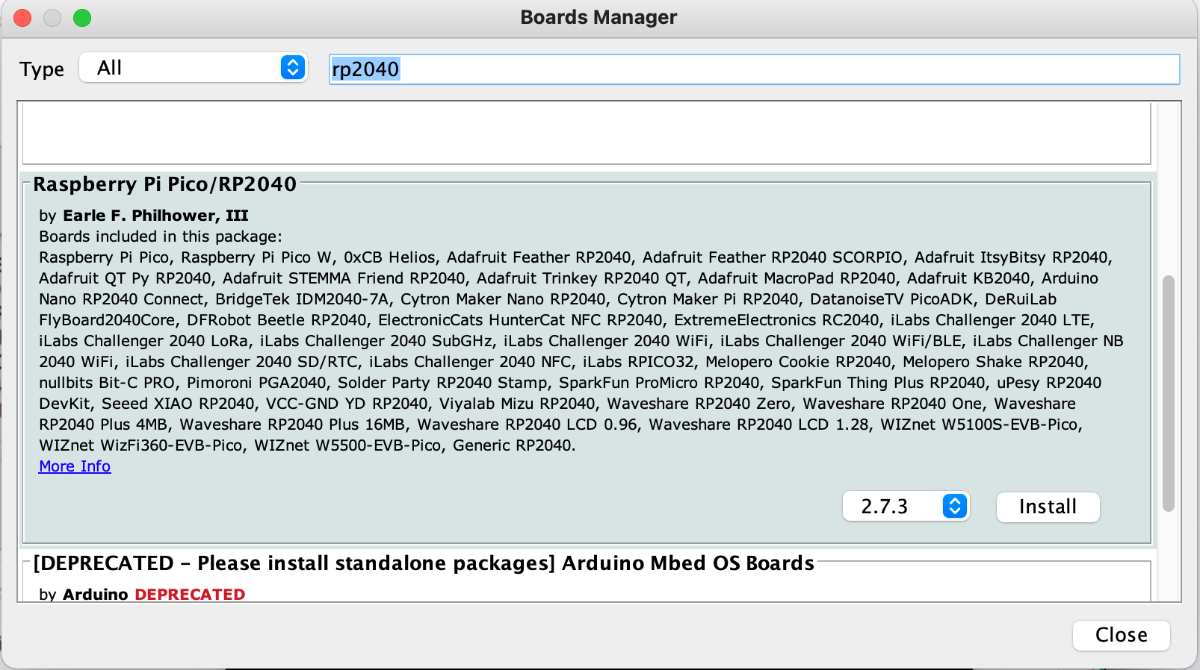
- Then in Tool > Board > Boards Manager... I searched for "RP2040" in the field. I found Raspberry Pi Pico/RP2040 and installed it as prompted.
- In Tools > Board I selected my board - Seeed Studio XIAO RP2040
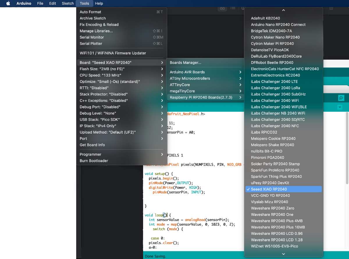
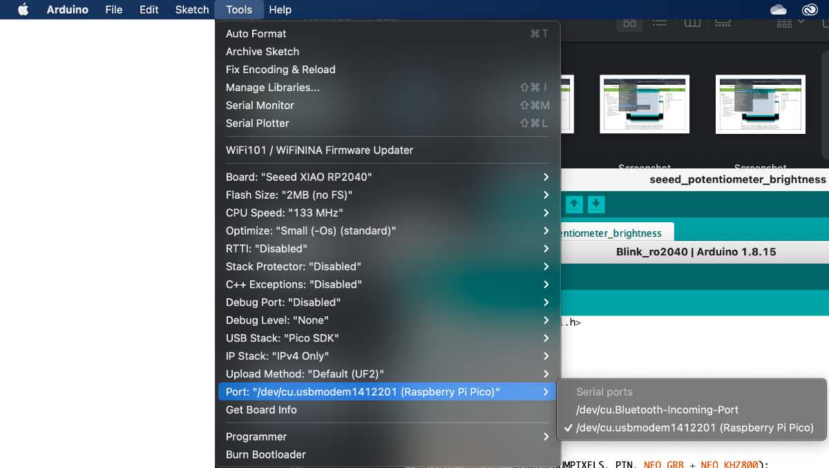
- In Tools > Port I selected the respective port - it had Seeed Studio XIAO RP2040 in parenthesis
- I opened the basic blink example code in File > Examples> 01.Basics > Blink
- I uploaded the code to the board by clicking the Upload icon in the top left corner
- Everything worked as expected and the LED on the board started blinking
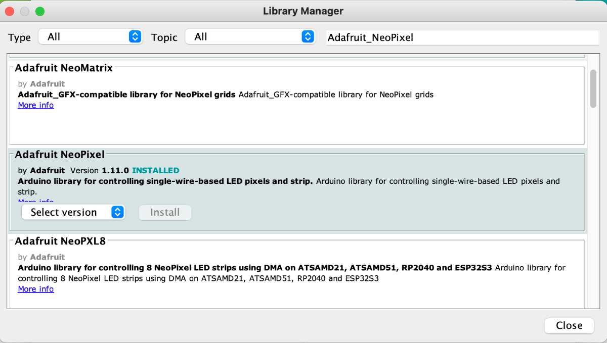
- I followed the same process as above, however this time, as I wanted to use the Neopixel avilable on the board with Arduino, I needed to install the respective Adafruit Neopixel library (documentation and references)
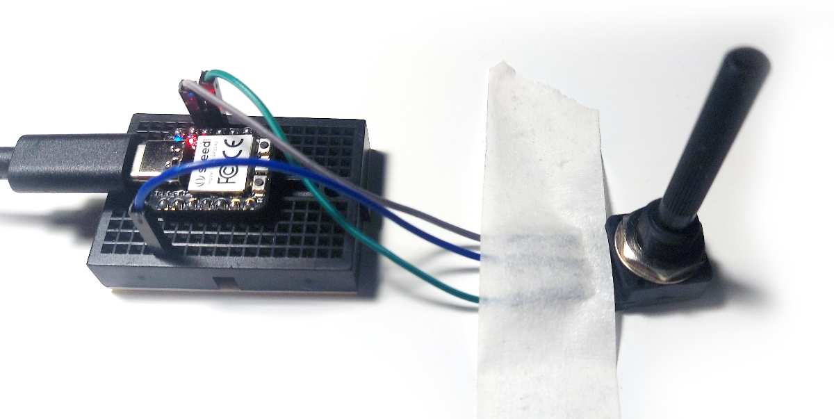
- I made a circuit using an analog potentiometer, breadboard and jumper wires. I connected the potentiometer's middle signal pin to the A0 pin of the board - topmost left one. I used 3.5 voltage pin
- I uploaded the code below into the board
#includeint Power = 11; // the board's predefined power pin int PIN = 12; //the board's predefined RGB LED pin const int sensorPin = A0; //my potentiometer's signal pin is connected to A0 pin of the board int brightness = 0; #define NUMPIXELS 1 Adafruit_NeoPixel pixels(NUMPIXELS, PIN, NEO_GRB + NEO_KHZ800); void setup() { pixels.begin(); pinMode(Power,OUTPUT); //set up the power pin as an output digitalWrite(Power, HIGH); //turn the LED on pinMode(sensorPin, INPUT); //set up the A0 pin connected to the potentiometer as an ipnut } void loop() { int sensorValue = analogRead(sensorPin); //read the potentiometer analog value (range between 0 to 1023) brightness = map(sensorValue, 0,1023, 0, 255); //map the potentiometer range to LED values range (0 to 1023 mapped into 0 to 255) pixels.clear(); pixels.setPixelColor(0, pixels.Color( brightness, brightness, brightness)); //assign the mapped value to LED red, green and blue values pixels.show(); } - After some minor error fixing, the code and board worked as expected
upgrade to write and receive Serial messages
In order to have some more preview and control over what is happening on the board, I wanted too use the Serial class. I used it to display the value read from the potentiometer, so I could see if the circuit works properly and if the sensor is not damaged. I also introduced four possible states of the LED brightness to be displayed: dark, dim, medium and bright, according to the mapping of the sensor value
I used this tutorial from Seeed to setup the basic connection to Serial. Then I found Arduino reference useful trying to access and display different data types with Serial (string of characters and a variable). This Arduino reference helped me to write the code that would define the four cases reflecting the four possible states of the LED brightness - the SWITCH function. It actually also used the same application of sensor and LED info states.
#includeint Power = 11; int PIN = 12; const int sensorPin = A0; int r = 0; int g = 0; int b = 0; int brightness = 0; #define NUMPIXELS 1 Adafruit_NeoPixel pixels(NUMPIXELS, PIN, NEO_GRB + NEO_KHZ800); void setup() { Serial.begin(115200); // initialize the Serial function with 115200 bitrate while (!Serial); pixels.begin(); pinMode(Power,OUTPUT); digitalWrite(Power, HIGH); pinMode(sensorPin, INPUT); } void loop() { int sensorValue = analogRead(sensorPin); brightness = map(sensorValue, 0,1023, 0, 255); int brightnessCase = map(sensorValue, 0,1023, 0, 3); //mapping the potentiometer read sensor value to 4 possible cases using the switch function switch (brightnessCase) { // the switch function defining what happend it the first scenario (case 0) case 0: { String info="dark"; // assigns the text "dark" to the string of characters INFO, that will later be displayed if this case is initialized break; } case 1: { String info="dim"; break; } case 2: { String info="medium"; break; } case 3: { String info="bright"; break; } pixels.clear(); pixels.setPixelColor(0, pixels.Color( brightness, brightness, brightness)); pixels.show(); String info; Serial.println(sensorValue); // prints the reading of the potentiometer values in the Serial Monitor Serial.println("It's "); // prints the text "It's" as is Serial.println(info); //prints the string of characters "info" according to the information from the active case delay(1000); } } 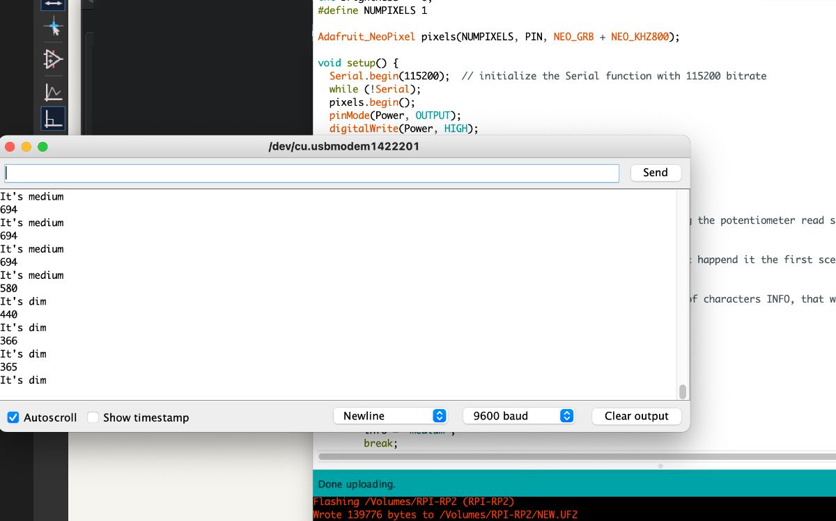
Group Assignment page