Computer Aided Design
CAD
Computer Aided Design (CAD) is a technology that uses computers to create, modify, analyze or optimize designs. It helps in creating 2D or 3D digital models of objects, structures or systems. CAD is widely used in various fields such as architecture, engineering, manufacturing, and Fab Academy of course.
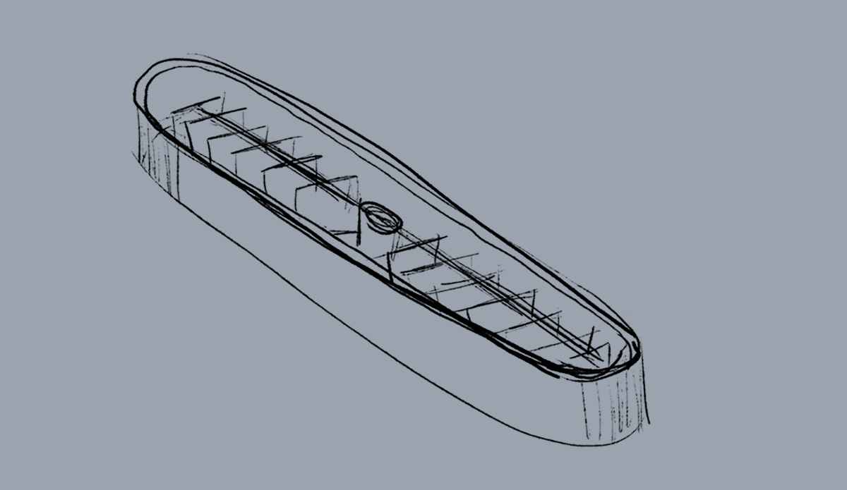
Modelling a silicone gripper mold with Rhinoceros
This is a modification of a generic design of a mold for making silicone soft robotics grippers. They usually have 4 arms that wrap around an object to grip it, I however would like to have a bracelet-like actuator.
Sketch the geometry

Draw the initial circle
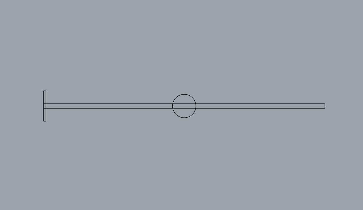
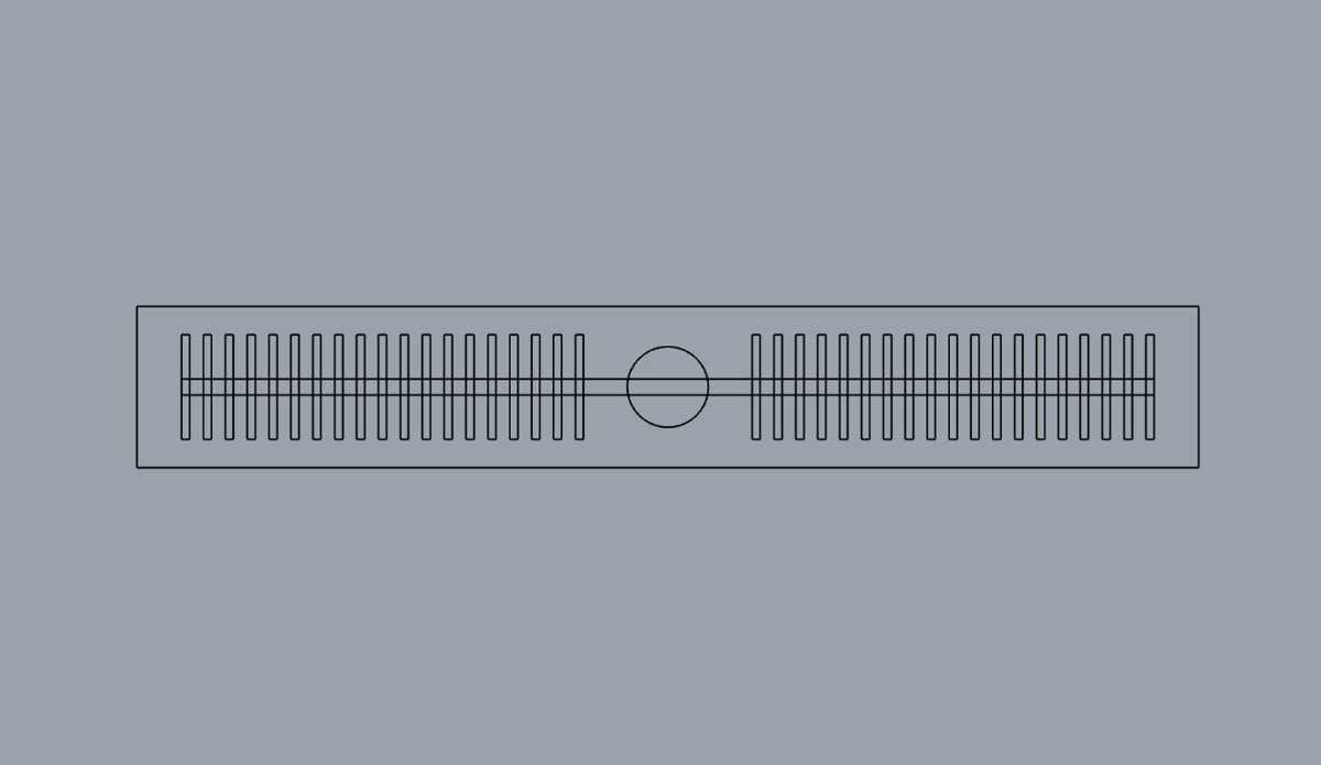
Draw the rectangle of the main air duct and for the initial separator
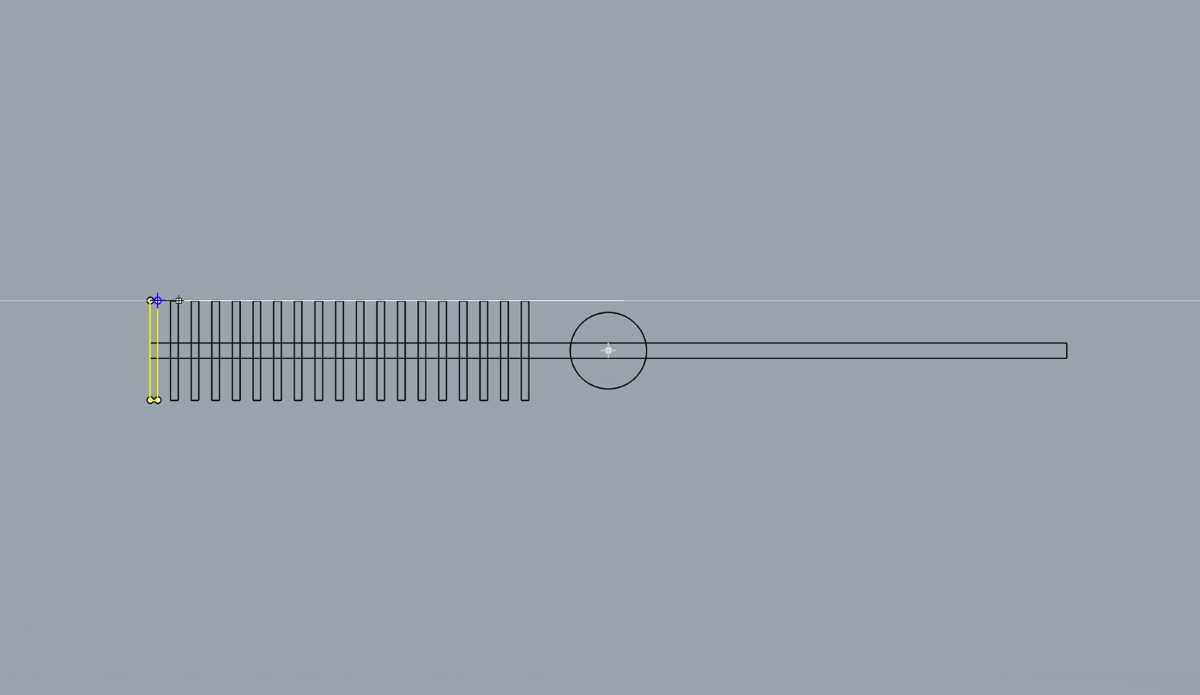
Apply linear array to copy the separators along the x axis
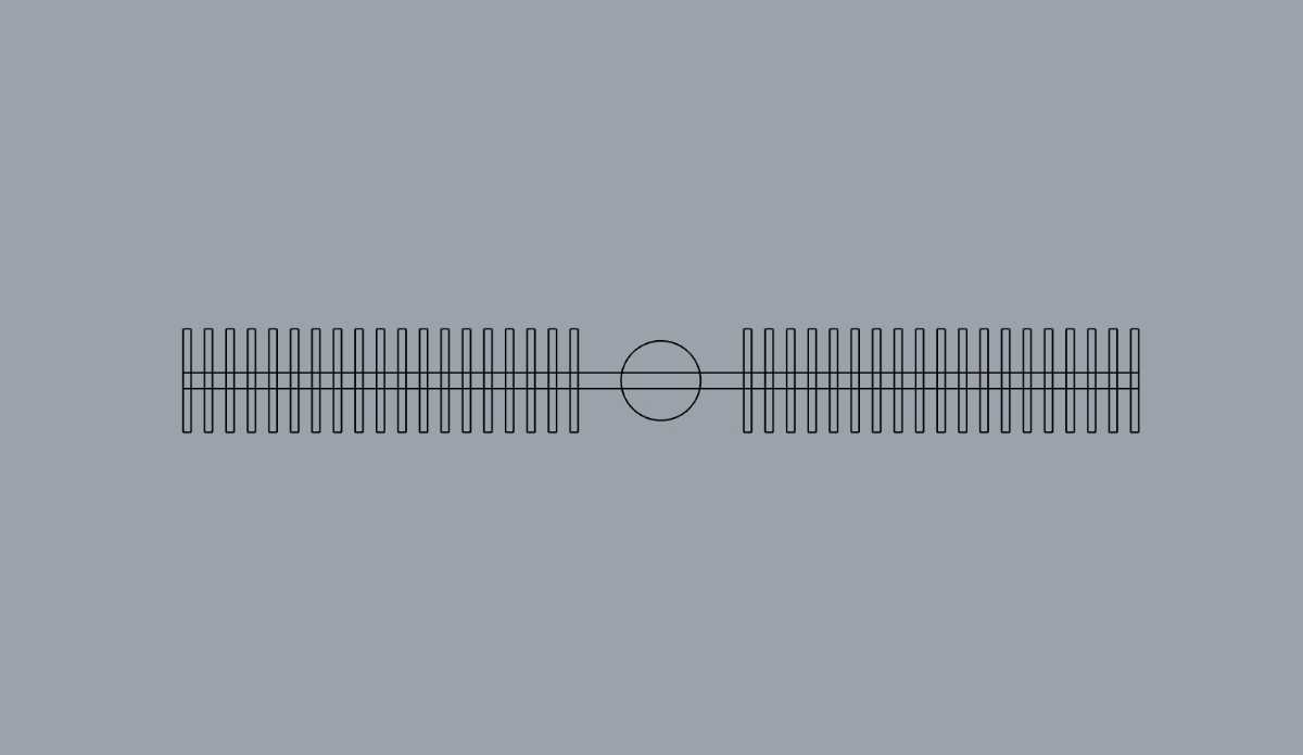
Mirror the separators to the other side of the design
Draw the outer rectangle
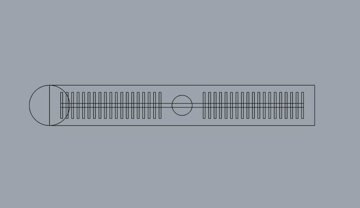
Draw a circle at the end to round the edge
Trim the unnecessary edges and mirror the cap
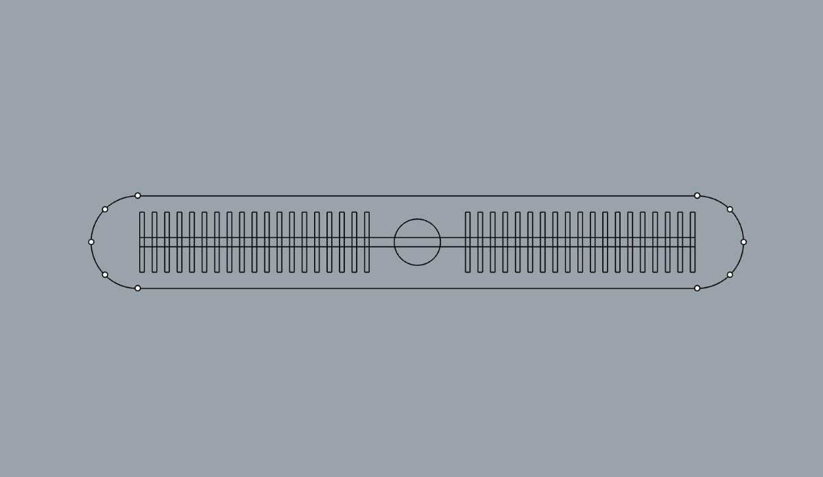
Join the curves to create continous path
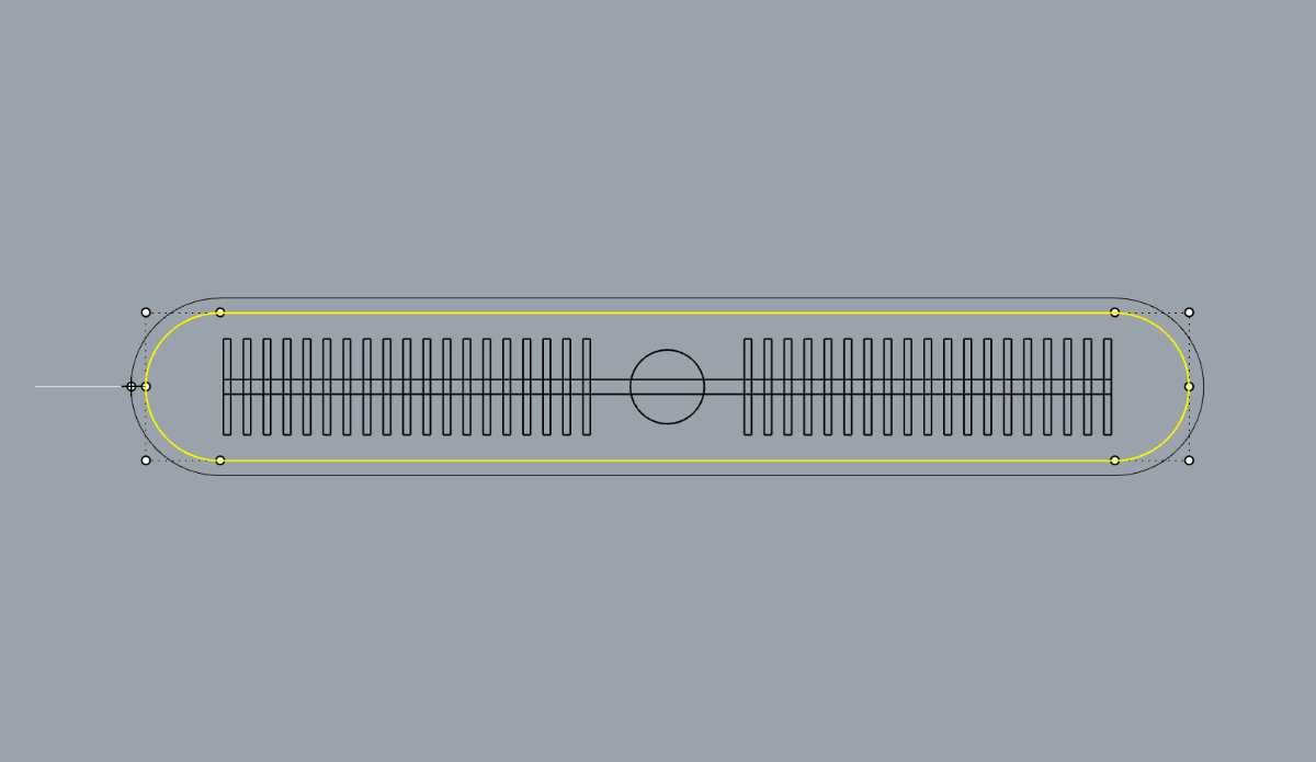
Apply offset along the curve in the outside direction
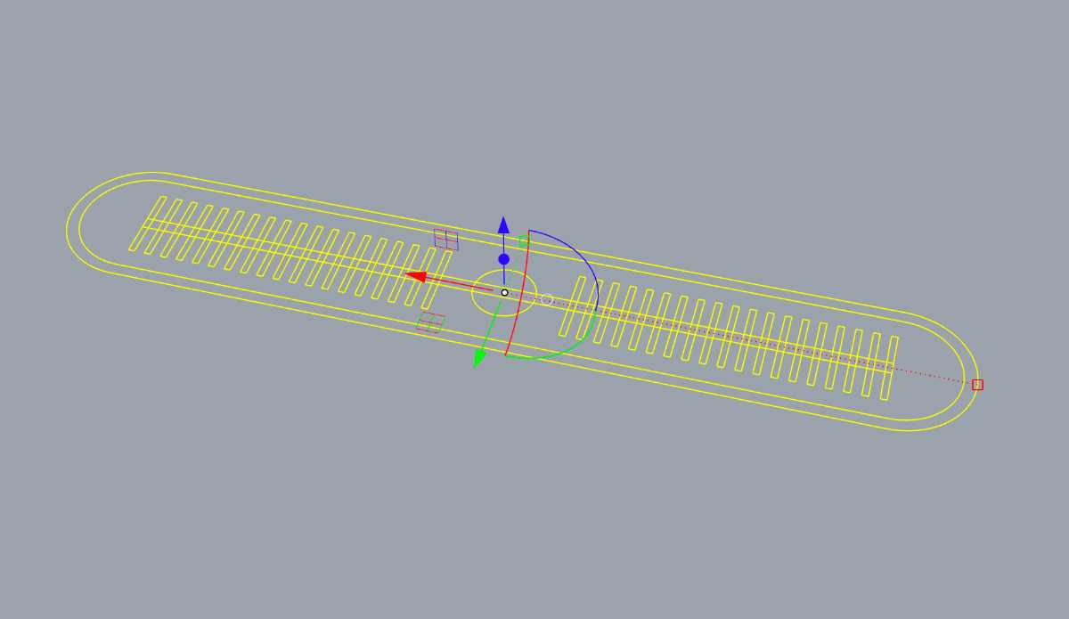
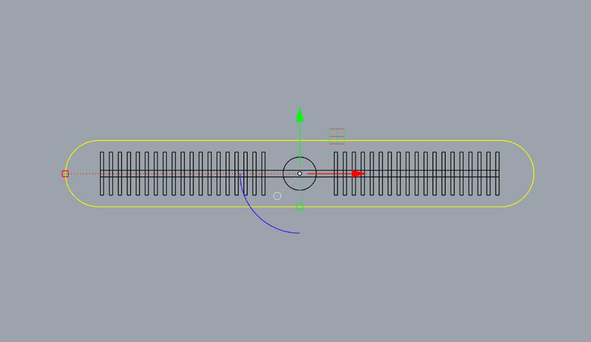
Switch to a perspective view
Extrude the outer contour curve to create the bottom of the mold
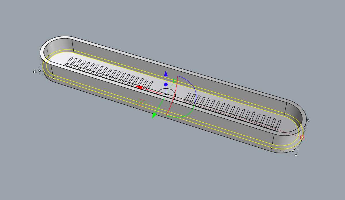
Select the outline curves and extrude them to form wall
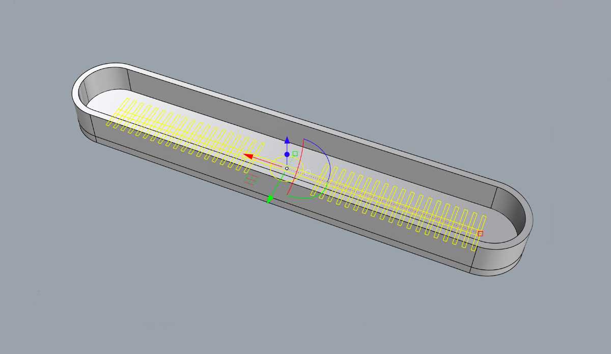
Select the curves forming the inner structure
Extrude them to create the geometry that would become the air channel after molding
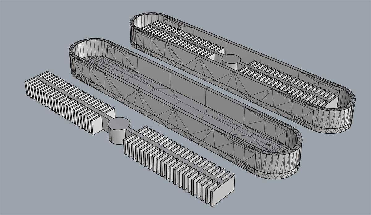
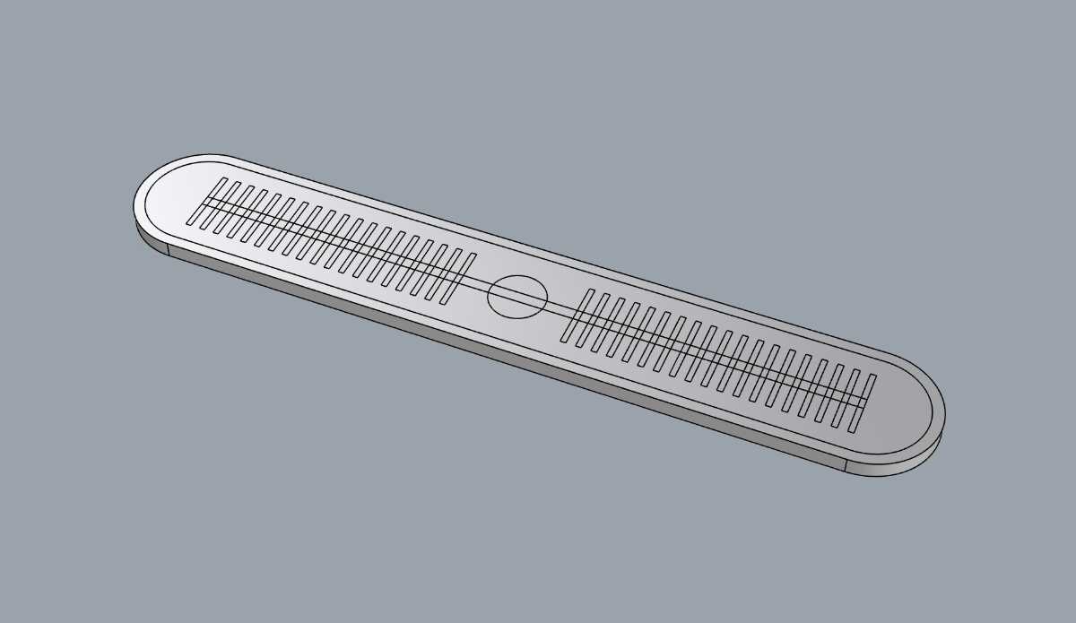
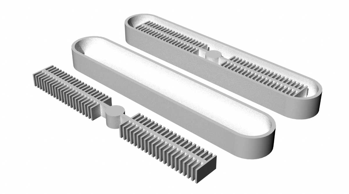
Mold parts
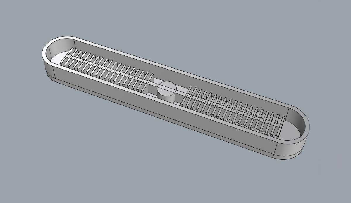
Rendered view of the mold
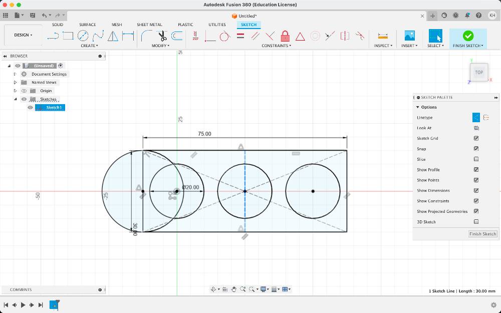
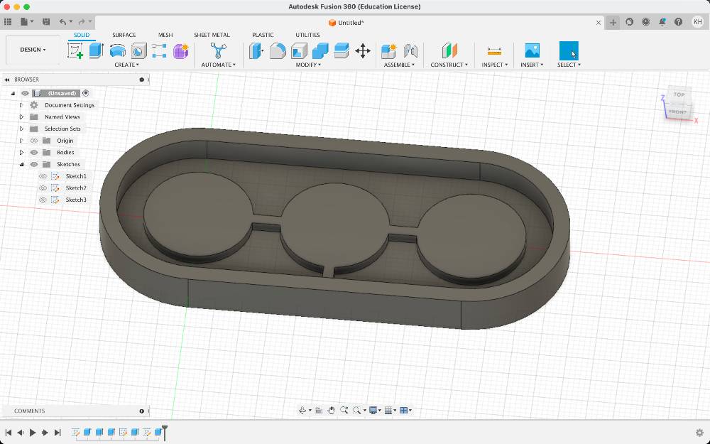
Modelling a silicone bubble mold with Fusion360
This is a mold for a pneumatic actuator that is intended to inflate on one side, forming three bubbles connected with air channels.
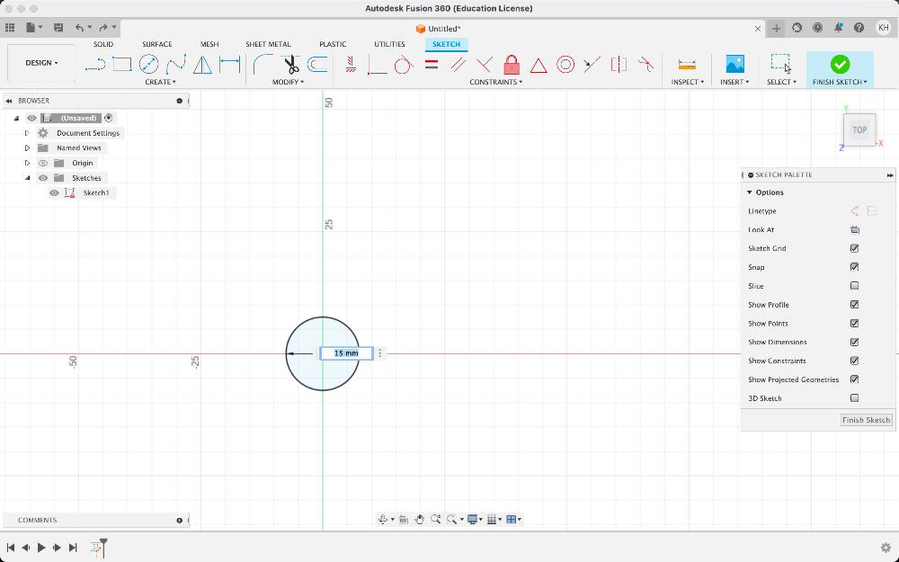
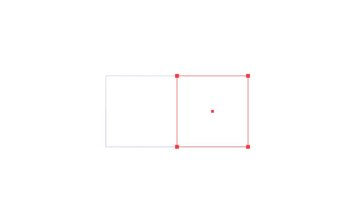
Open a sketch mode and draw the initial circle. Create a dimension that you can change later
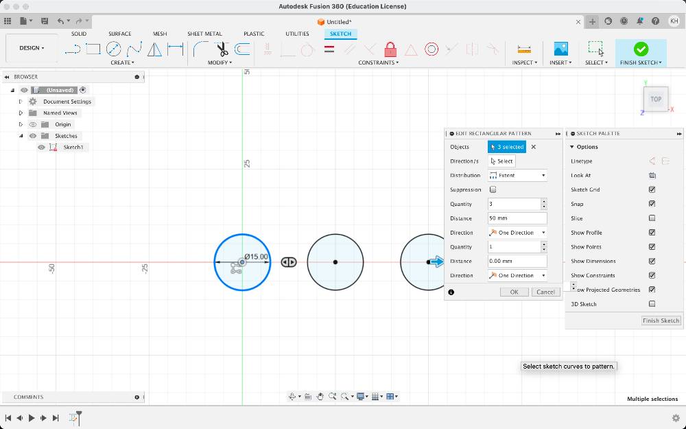
Select the circle and create a rectangular pattern
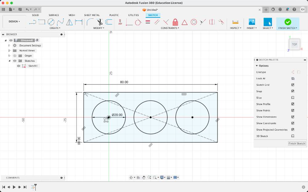
Draw the external rectangle
Draw a circle at the end
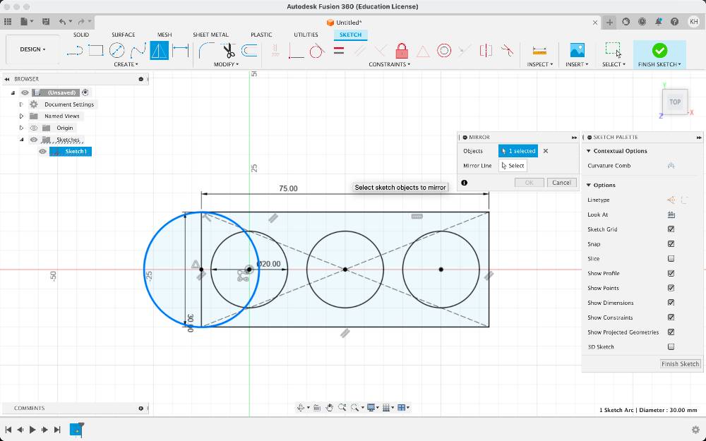
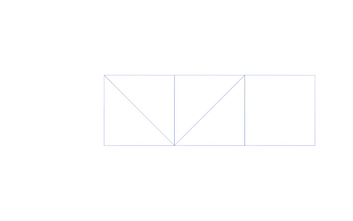
Draw a construction line in the middle that will be an axis for symmetry
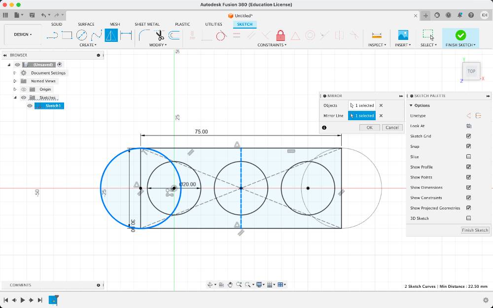
Apply mirror along the created line
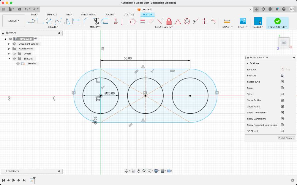
Trim the unnecessary curves
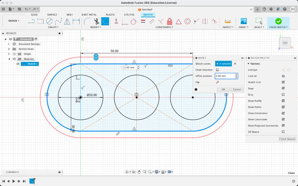
Offset the external curve
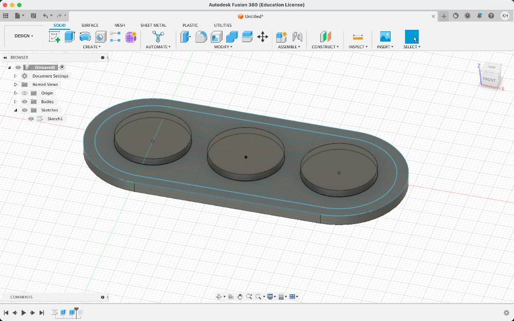
Extrude the outer contour curve to create the bottom of the mold
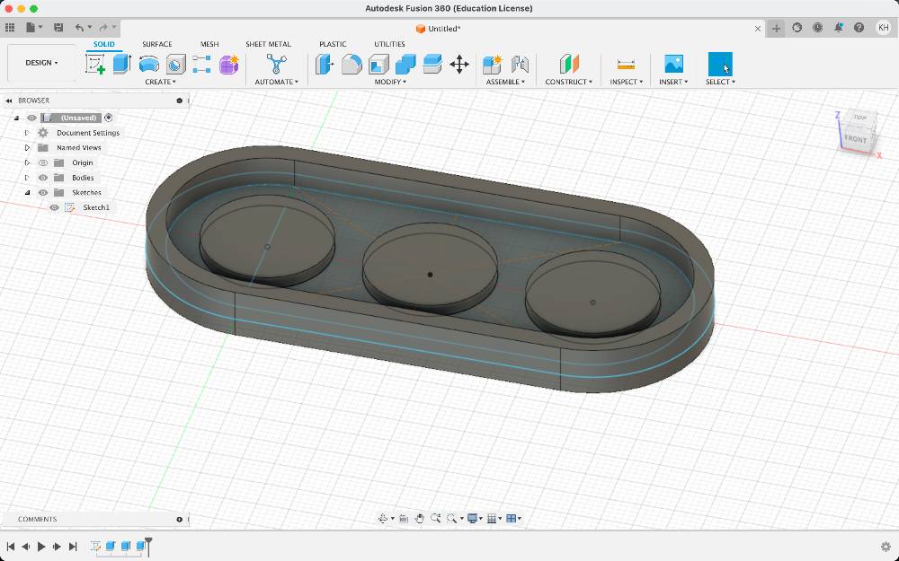
Select the outline curves and extrude them to form wall
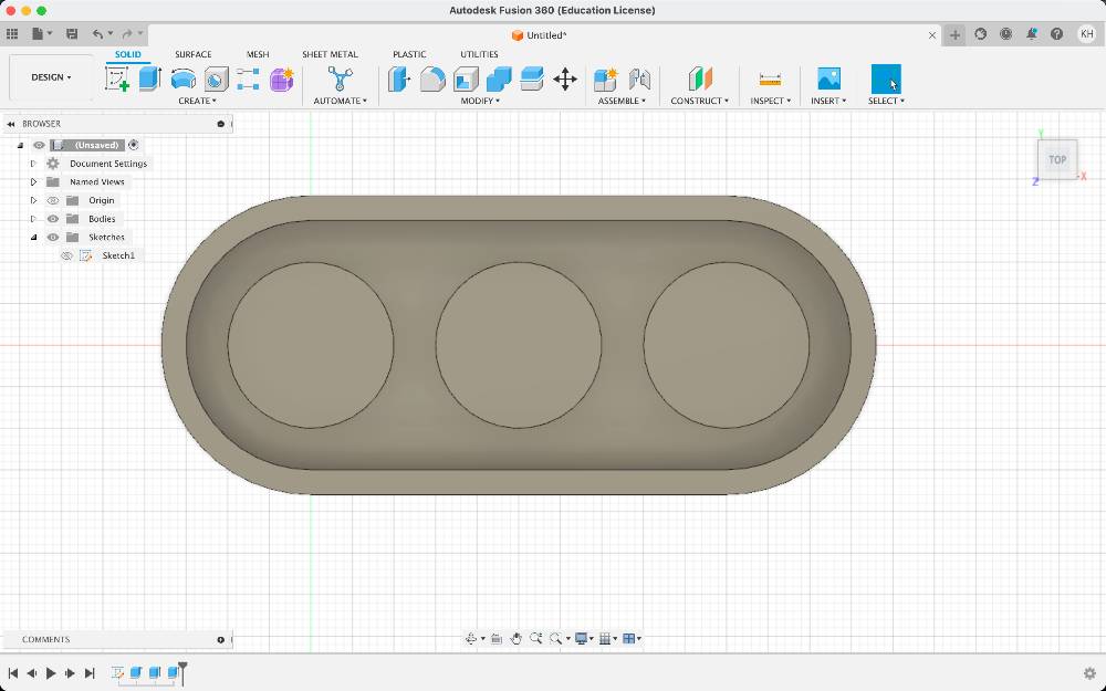
Switch to sketch in the top view
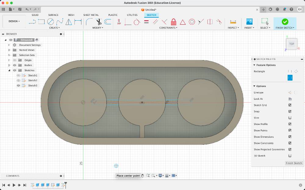
Draw a rectangle forming an air inlet
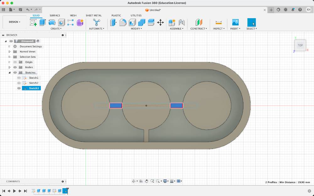
Draw rectangles to create the geometry that would become the air channel after molding
Extrude them
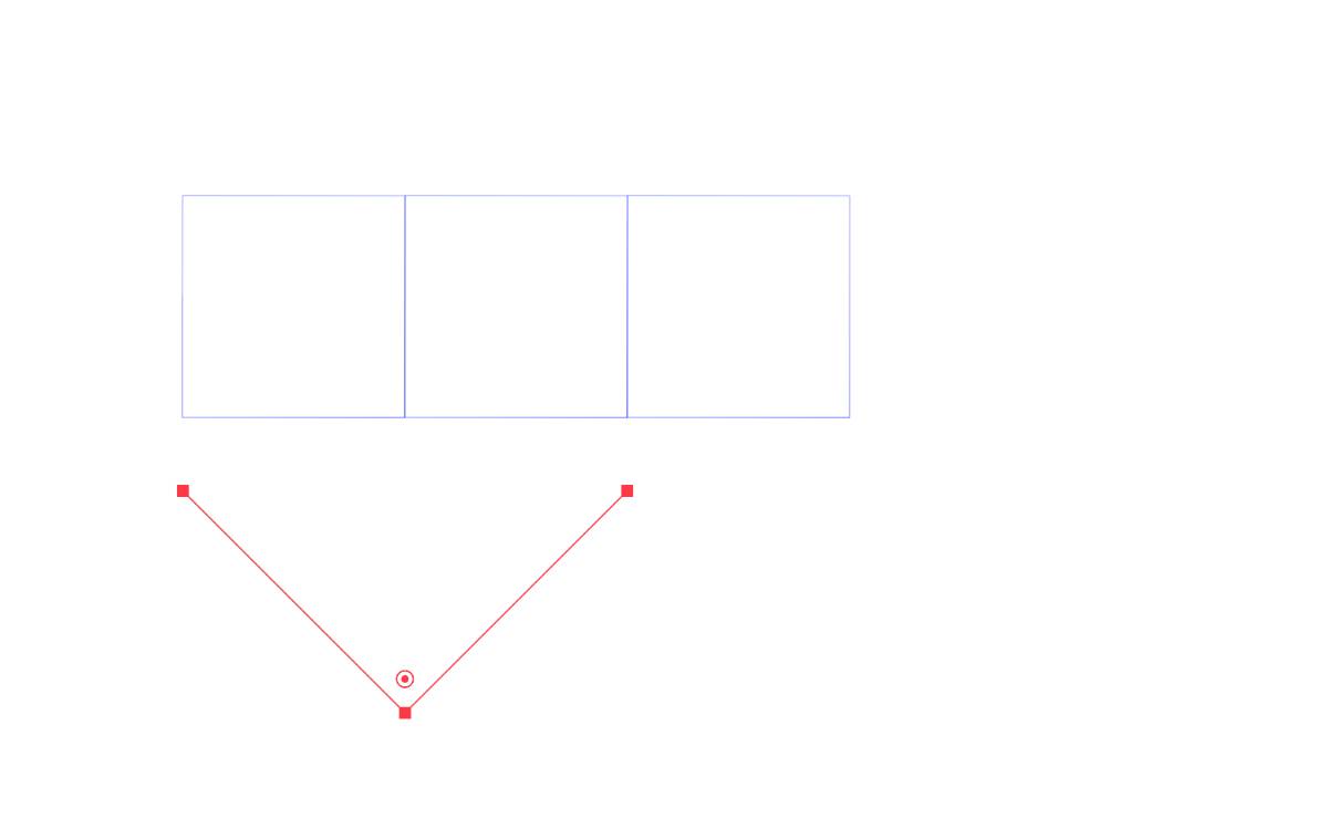
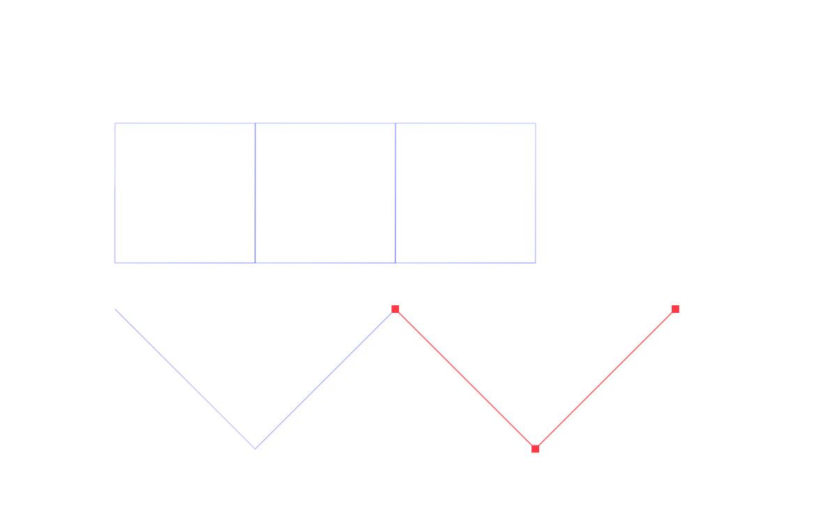
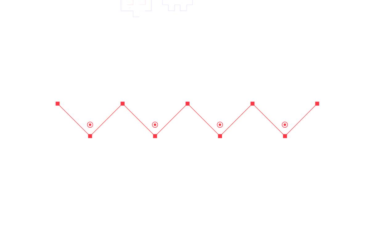
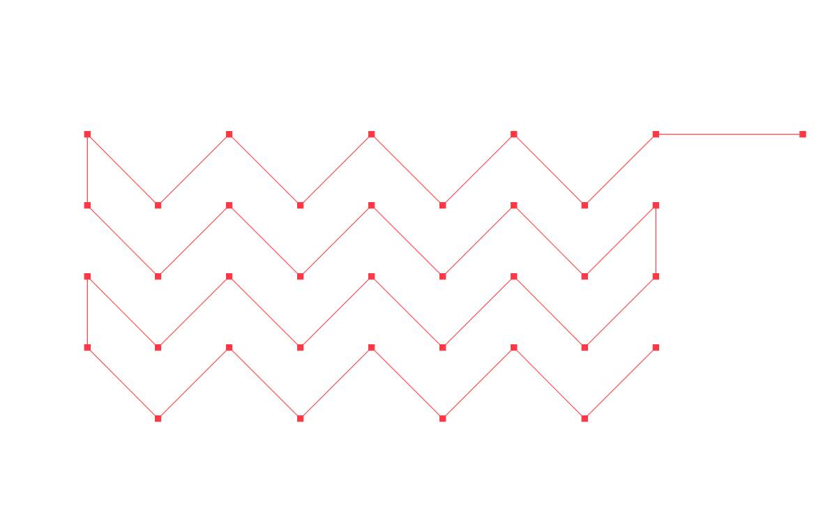
Adobe Illustartor - Designing an insert for lasercutting
I'm a graphic designer. Adobe Illustrator and 2D vector software have been my primary tools for many years now and I use them over the more complex CAD options whenever it's possible as I feel the most comfortable
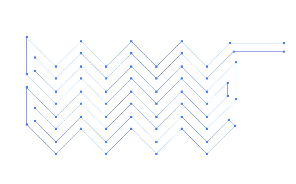
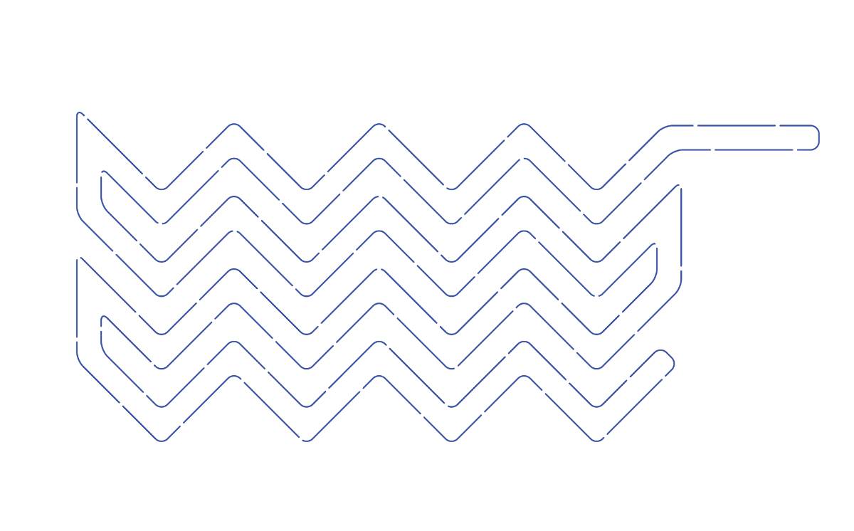
This design is a curvy shape to be lasercut in baking paper and used to fabricate a pneumatic actuator


Other software
I have used mesh-oriented 3D modelling software for animation and motion graphics purposes, including Autodesk Maya,Cinema 4D and ZBrush digital sculpting. They are great for more freestyle modelling, but meshes are difficult to edit which becomes a problem in an iterative design process that often is required in digital fabrication.
SolveSpace
During the local class Kris gave us a short introduction to SolveSpace - Open Source Cad software. Full tutorial available here It's an interesting open-source alternative to the other more popular CAD software options. The interface is not the most intuitive, but this program offers all the basic tools necessary for designing a part.
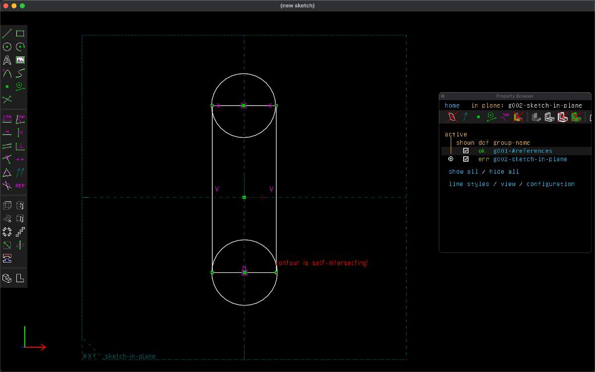
Solvespace UI
Inflation simulation
I'm trying to visualize an inflation of an actuator, but it seems to be a more advanced process. I know it sshould be possible with Rhino and Grasshopper with Kangaroo physics simulation that would visualize and calculate stretchiness of the silicone, but my skills with Grasshopper are insufficient at this point
I'm also trying to achieve the inflation effect with Maya and nCloth fabric simulation that has an option to simulate stiffness, strechiness and physics.