Electronics Production
File preparation - CopperCAM
-
In order to fabricate my circuit I opened the CopperCAM software. I created a New circuit - File>Open>New circuit
-
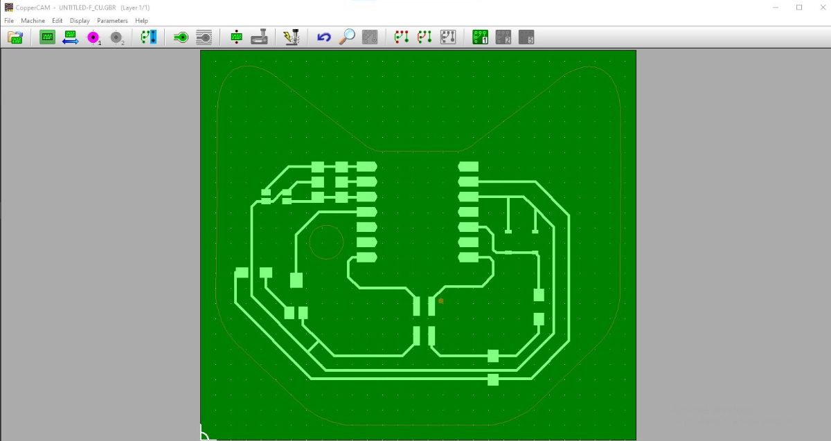
I imported the front layer - F_Cu.gbr file.
-
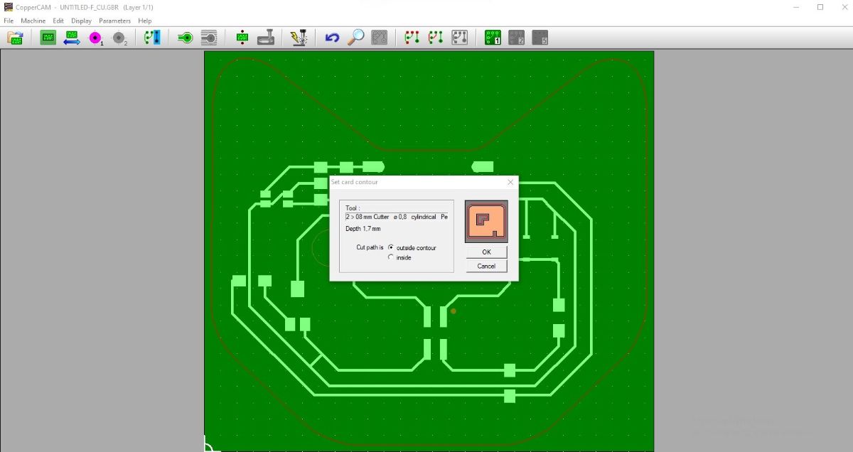
I right-clicked on the intended contour - the outer edge and clicked Define as card contour, setting it to outside contour (inside for any intended negative spaces)
-
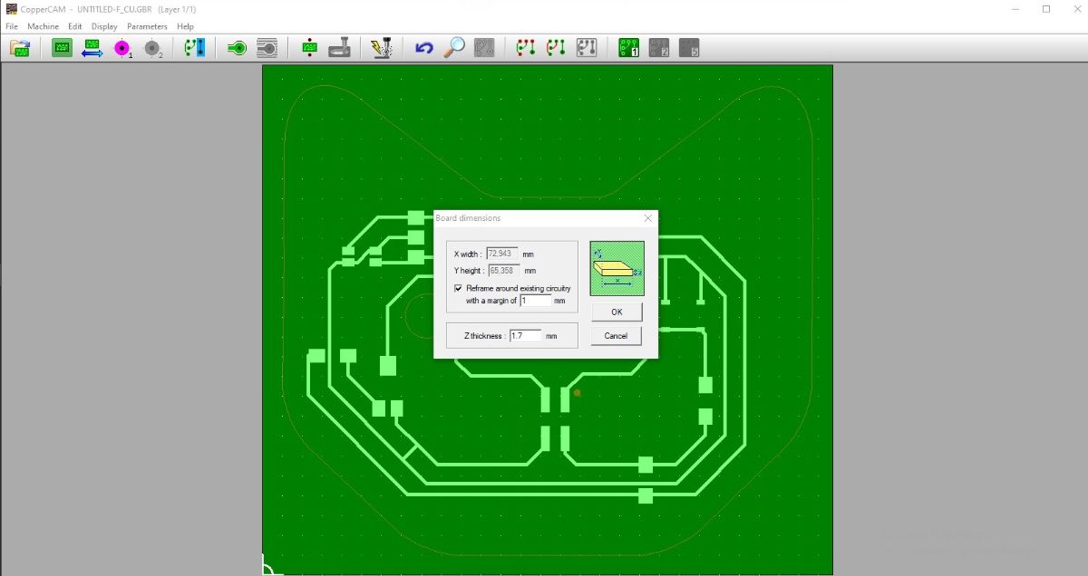
In File > Dimensions I set the margin to 1mm and Z thickness to 1.6mm around 0.1-0.2 more than the measured stock thickness
-
In File > Offset I set the Origin to X:0, Y:0 mm
-
In File > Open I clicked Additional layer, as I had one more layer to add to the circuit - the drilling holes NPTH gerber file
-
The layer didn't align as supposed - so I used the Reference pad option to align them
-
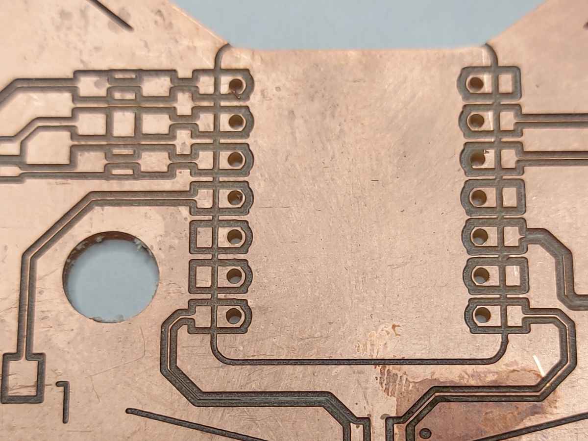
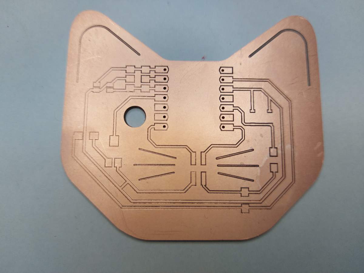
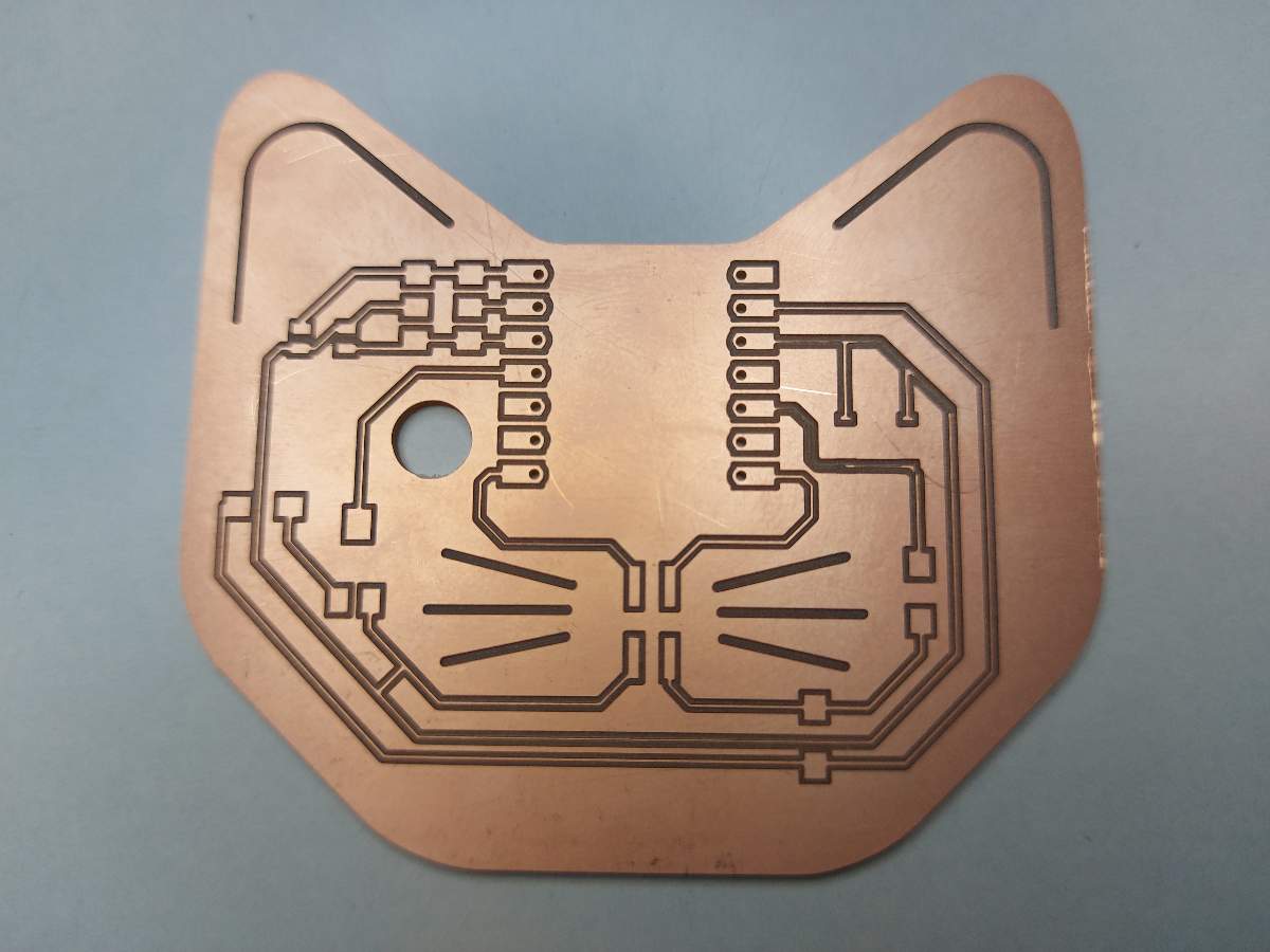
In my design I had lines that were for a decorative purpose only - the cat whiskers. In order to have then engraved only with one pass of the tool, I selected them, right clicked and clicked Engrave tracks as centerlines
-
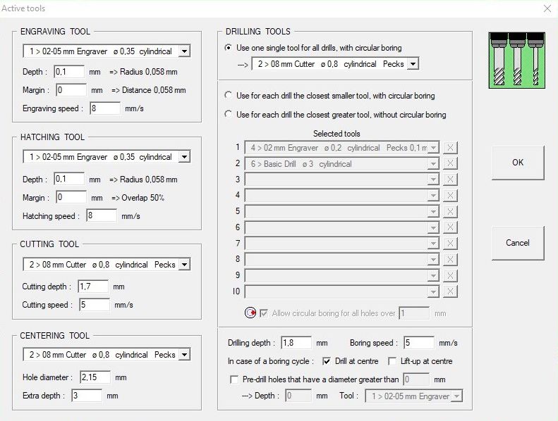
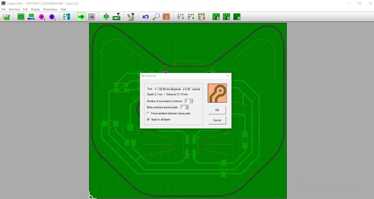
I proceeded to set up the tool necessary for the job - Parameters>Selected tools and filled as follows
-
I selected the >Calculate contours option to create the toolpaths and chose 4 passes
-
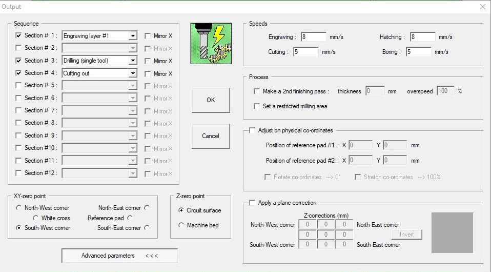
In order to save the files, I clicked the Mill option and filled the pop up window as follows. This way I got 4 .gbr files
VCarve and the board milling
-
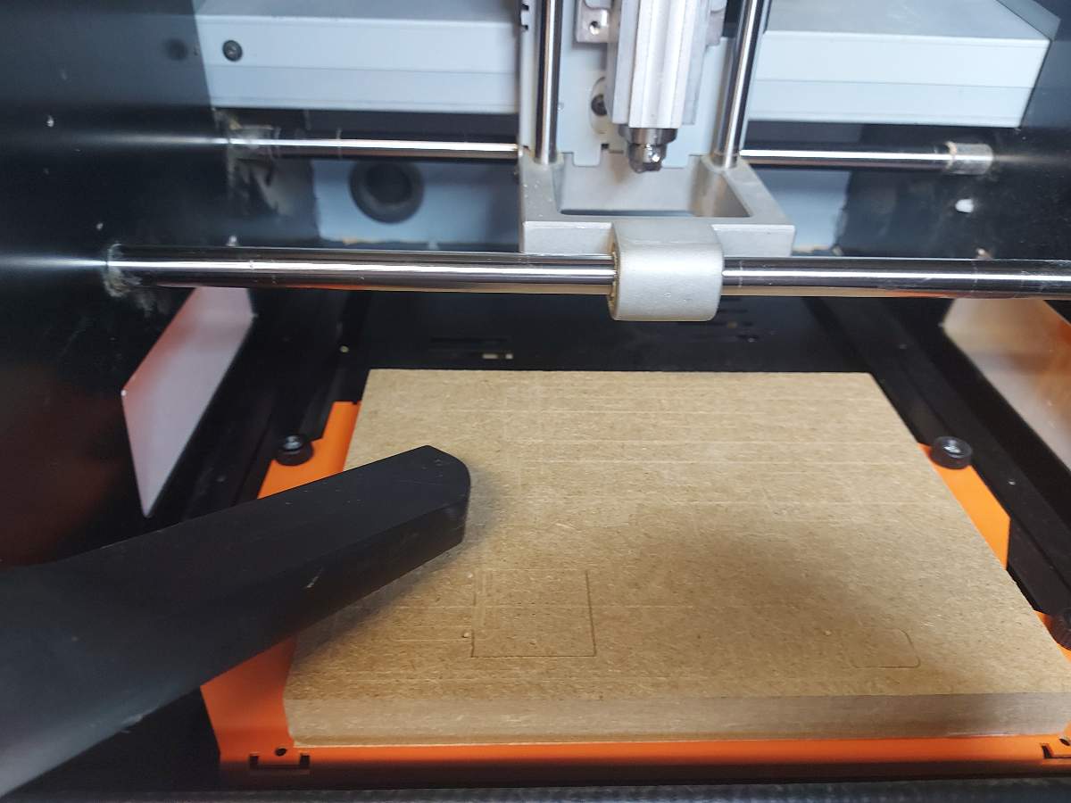
I cleaned the workspace and the inside of the machine with a vacuum cleaner in order to avoid any dust that could interfere with my milling later on
-
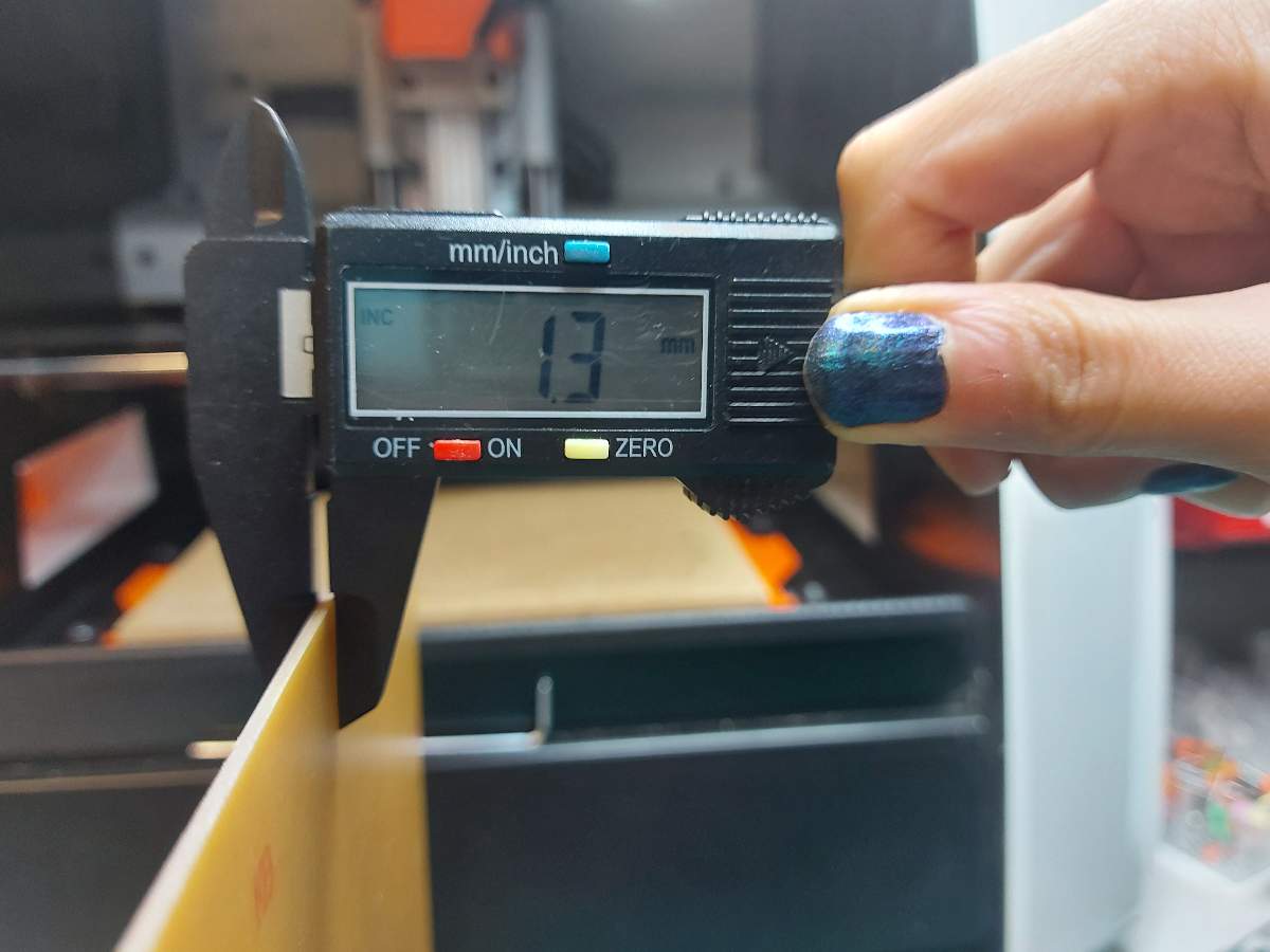
I carefully measured the thickness of my stock material
-
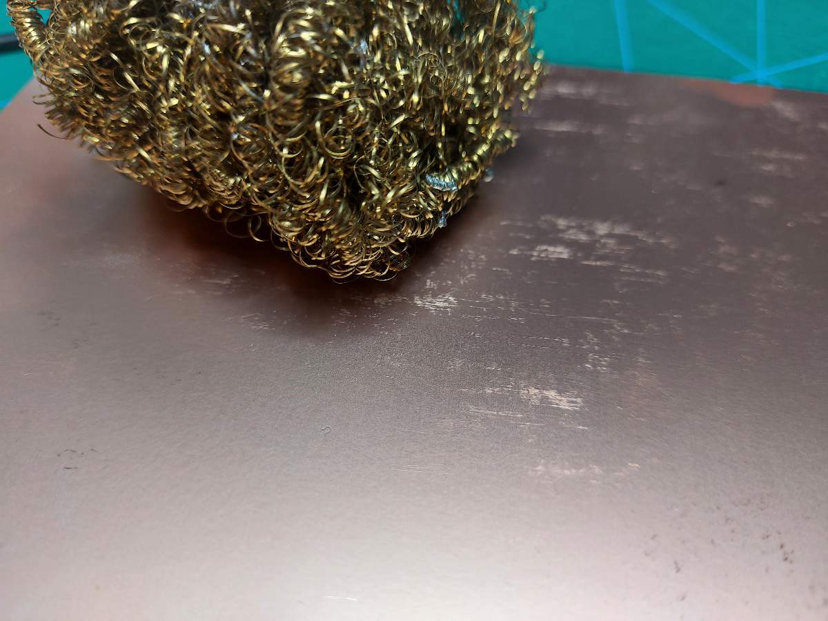
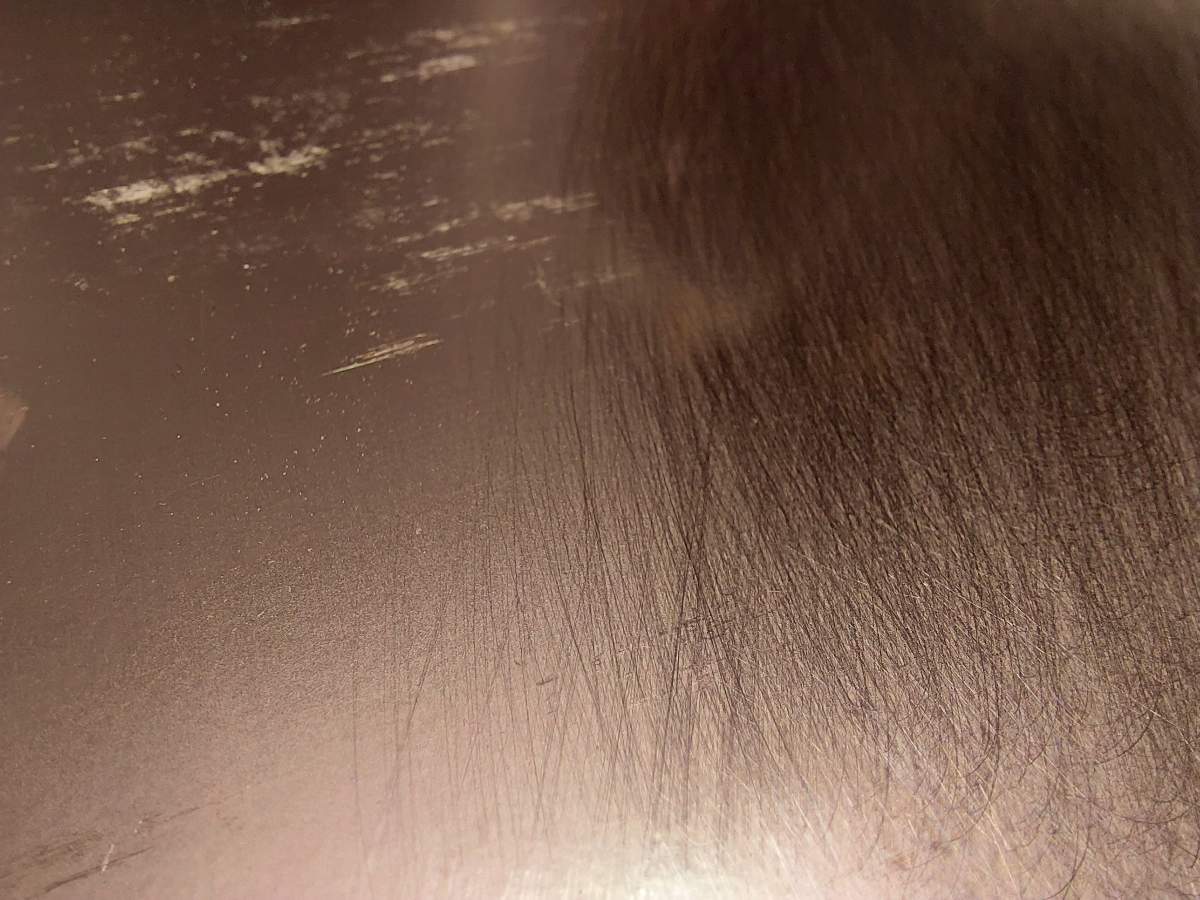
In order to make soldering easier, I removed the top layer covering the copper - by scratching it with metal wire
-
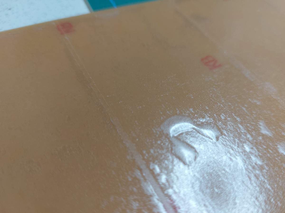
I put double-sided tape on the back side of the stock. It should be perfectly flat, no bubble like below, no overlapping, no dust
-
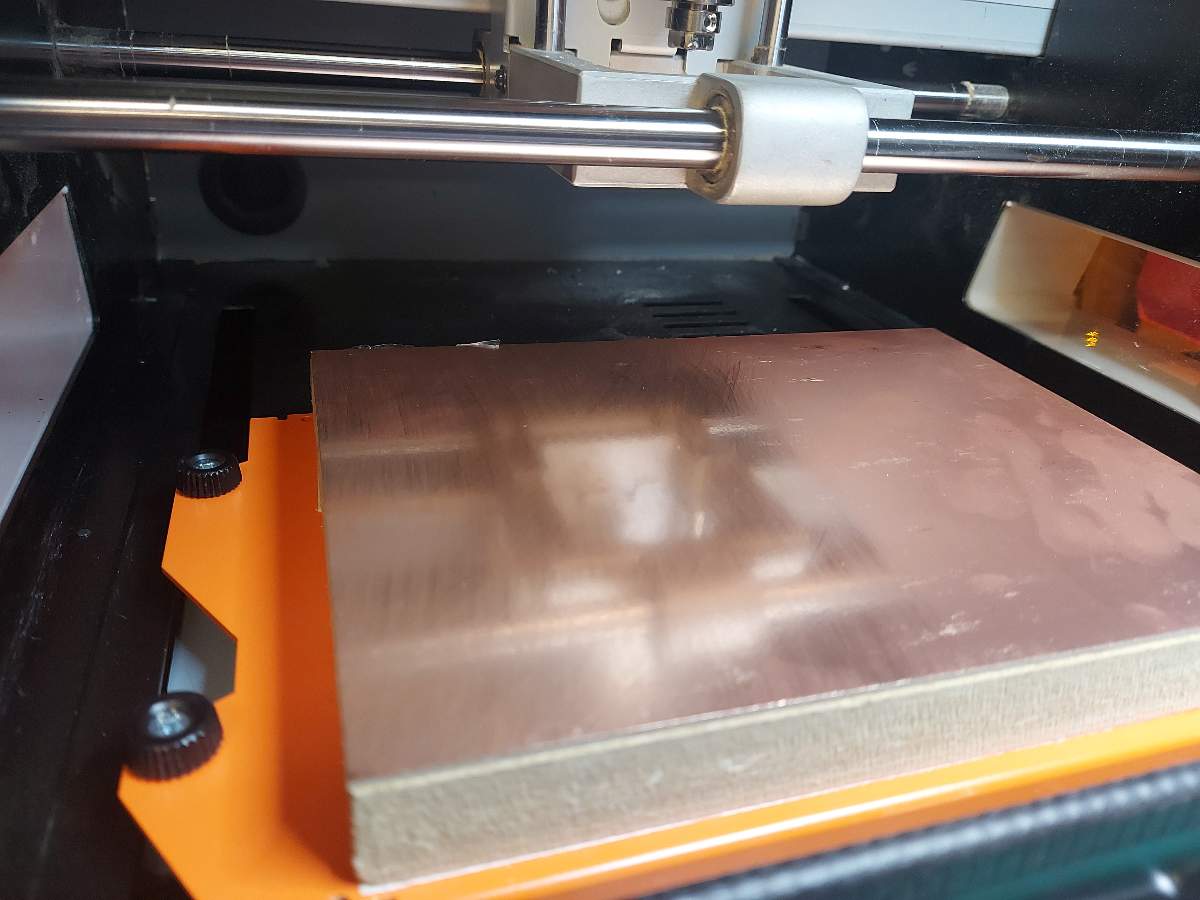
I placed the stock on the board attacched to the machine bed, again trying to make it as flat as possible
-
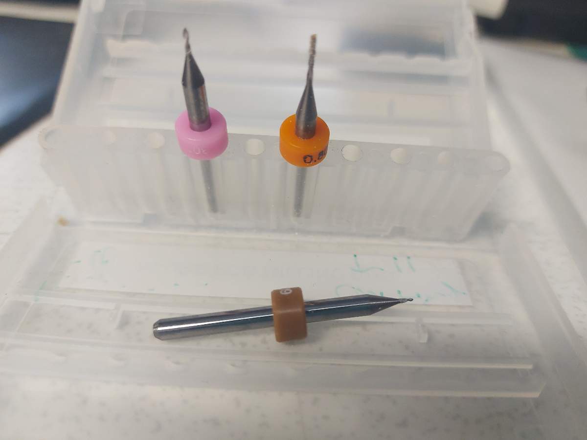
I checked if the bits I intended to use were not broken
-
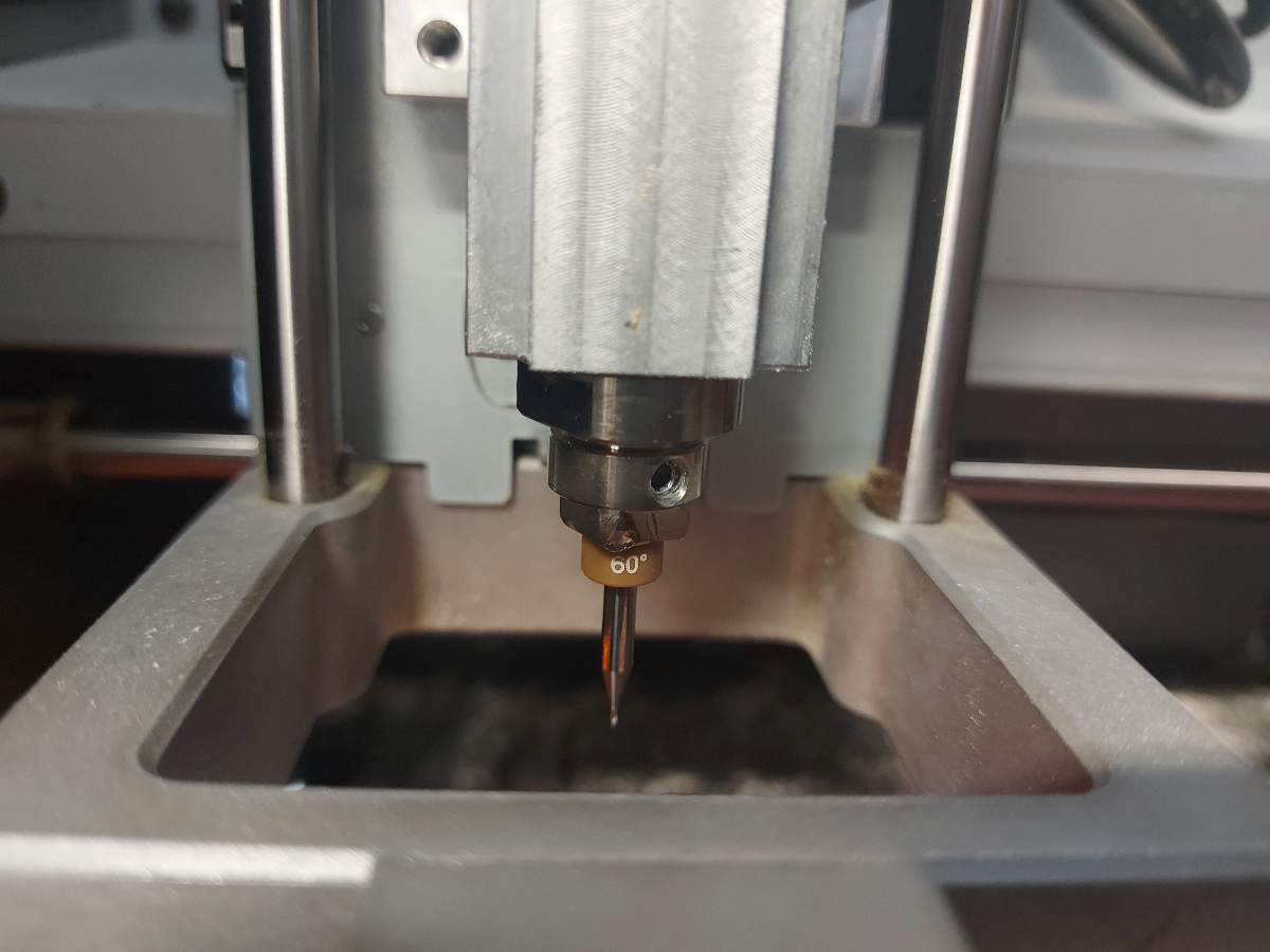
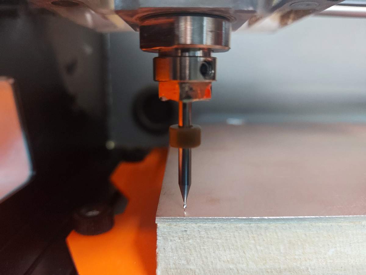
I placed the engraving 0.35 bit in the spindle (as far as possible) and temporary secured it with srewing it with the designated tool
-
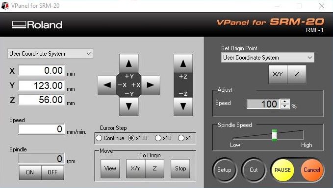
I opened the VPanel software and using the arrow buttons, I moved the spindle to the intended XY origin position (botttom left / south-west) over the stock. I clicked Set origin point > User coordinate system > XY
-
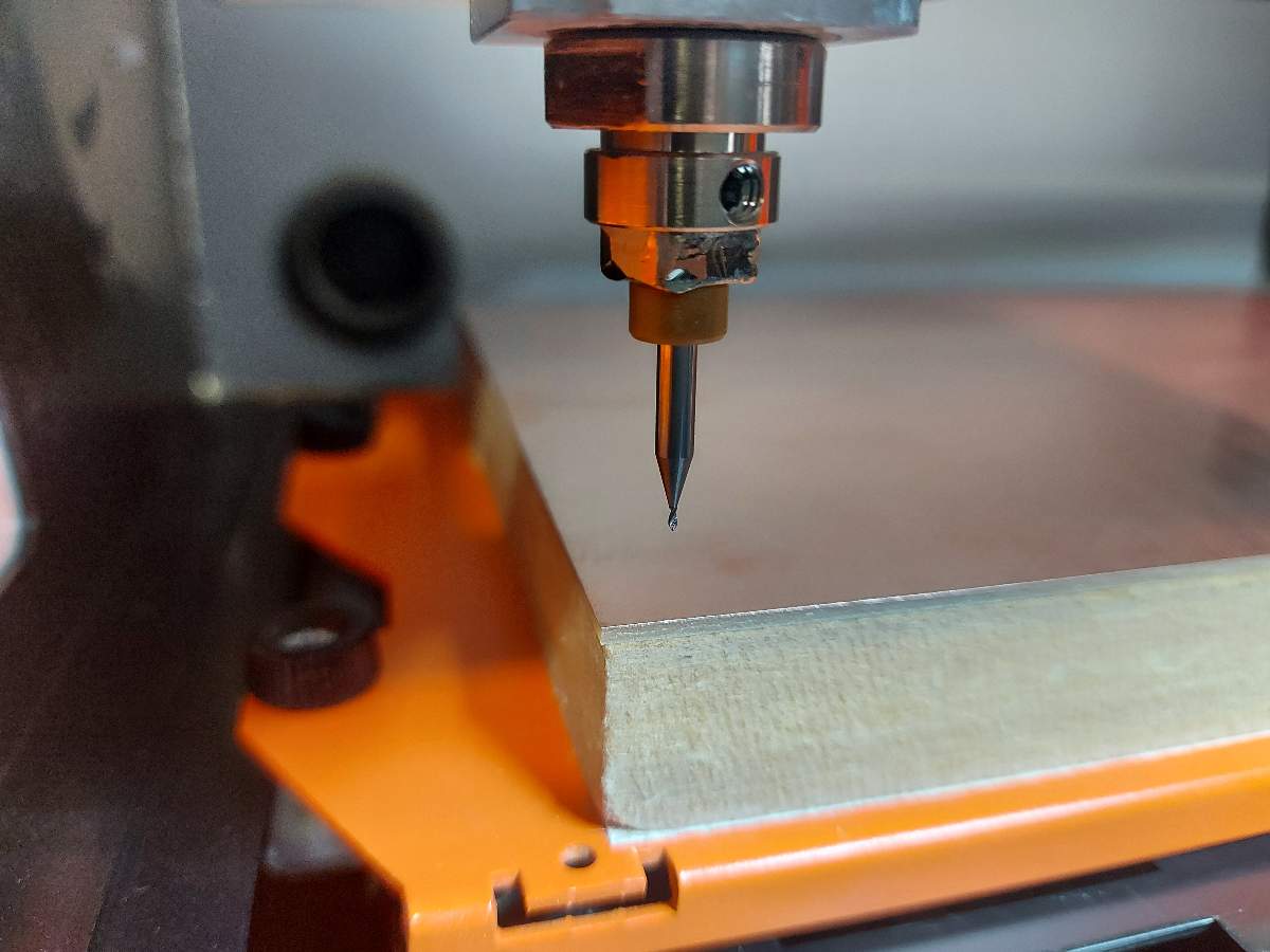
Low above the stock surface, I released the screw holding the tool tip for it to move down with gravity and touch the copper surface. I then tightened it again and clcked Set origin point > User coordinate system > Z
-
In Vpanel I clicked Cut and opened the first tool toolpath - engraving .egx file. I clicked Output to start the milling process
-
To perform the second operation - the drilling and then cutting - I had to change the bit to the 0.8mm one. I repeated the same process to set the new Z origin. Important - set the new origin pointONLYfor Z position leaving the original XY, otherwise the drilling and cutting would not be aligned
-
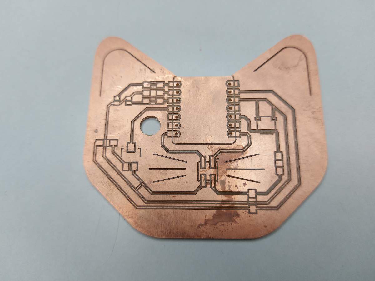
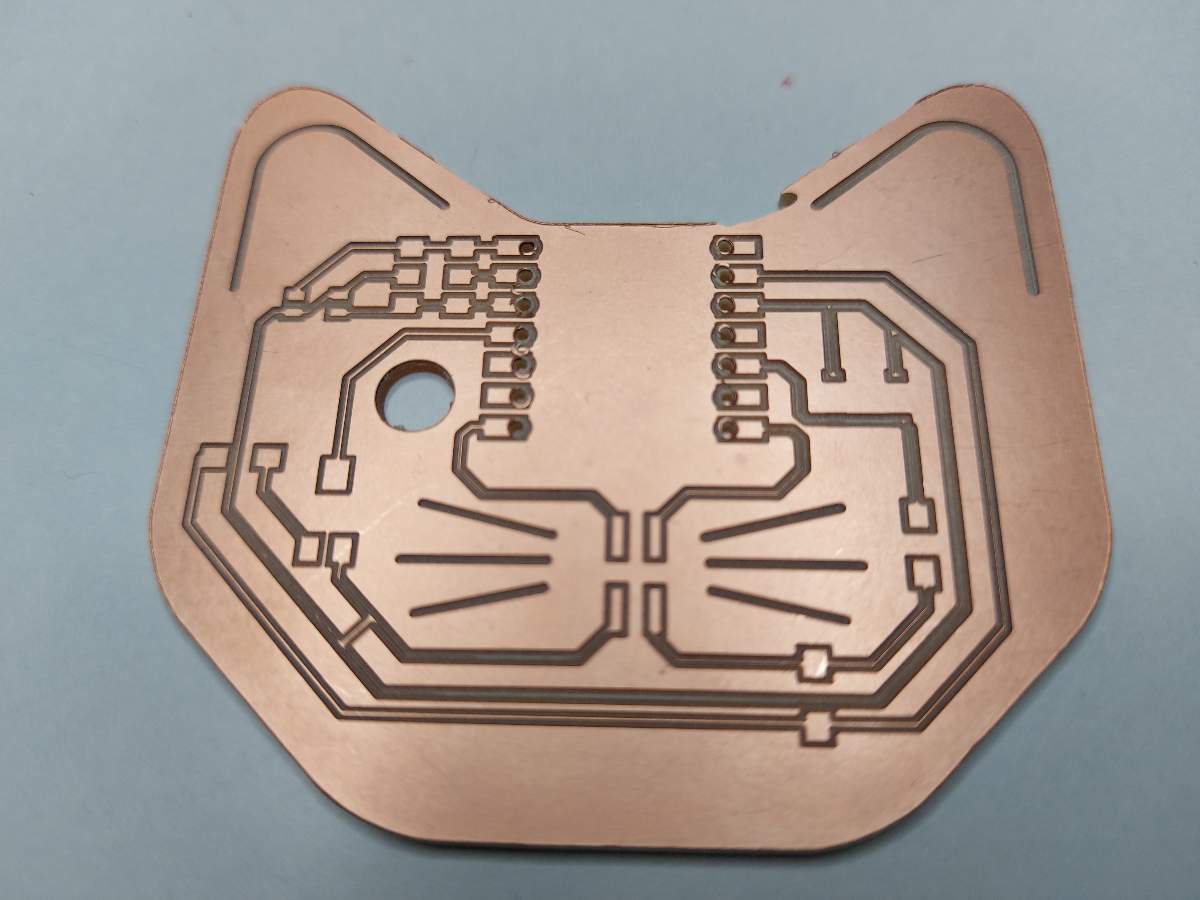
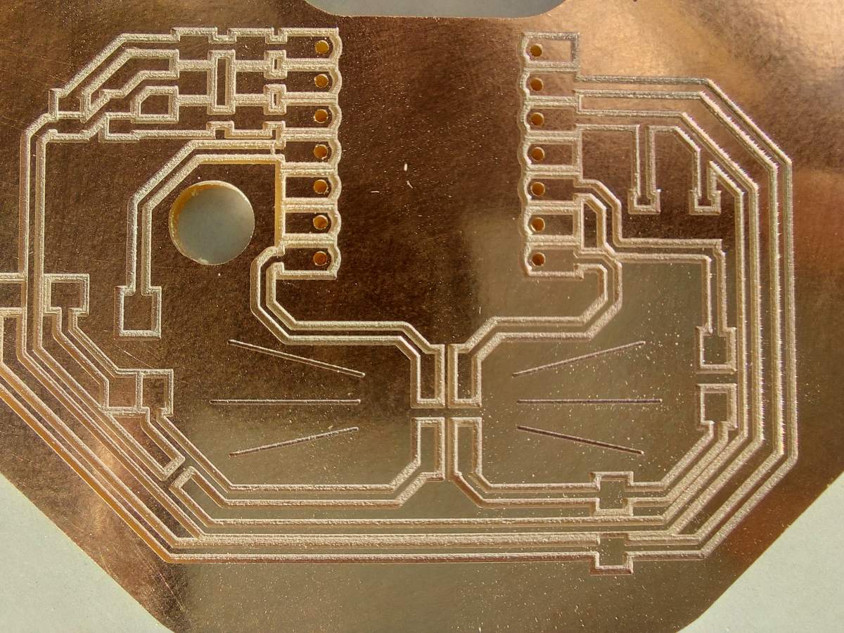
I got my board milled. I cleand all the dust with the vaccum cleaner and removed the tape
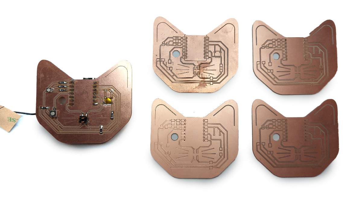
Fail gallery
It took a lot of tries to actually get the board milled properly
I included the Silscreen layer as I thought that was the way to get the graphics layer. Mistake. Any additional graphics should be added to the front/bacl copper layer and then set as Engrave tracks as centerlines option in CopperCAM
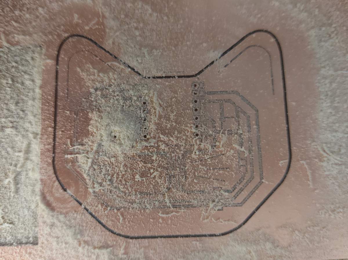
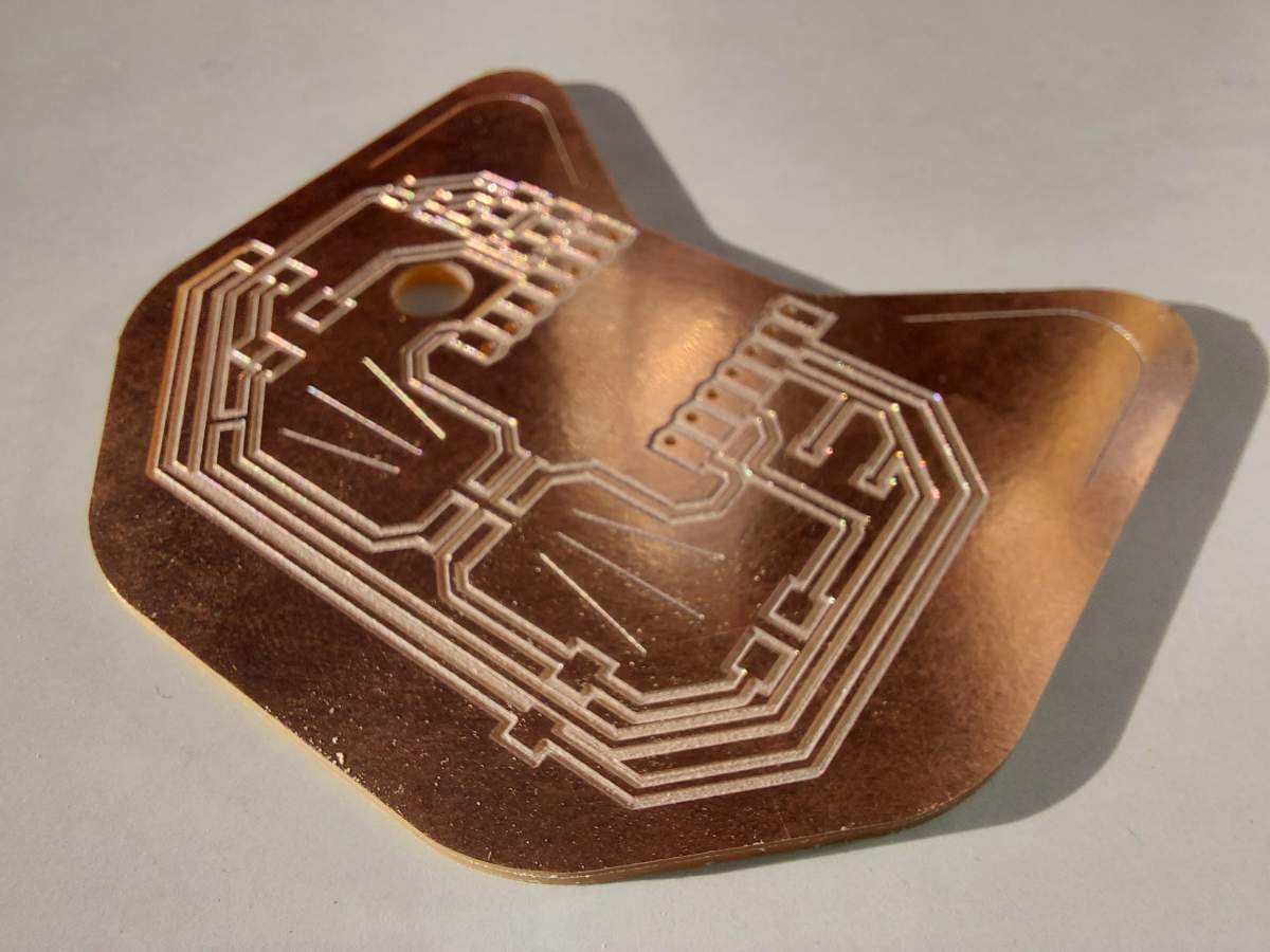
Too deep
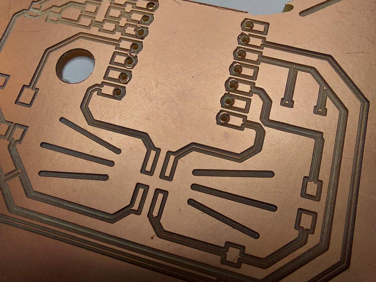
Not deep enough
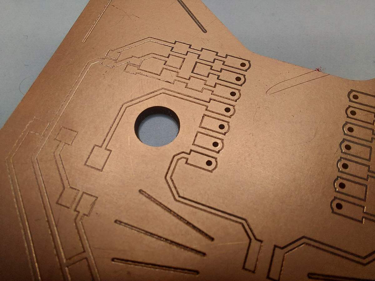
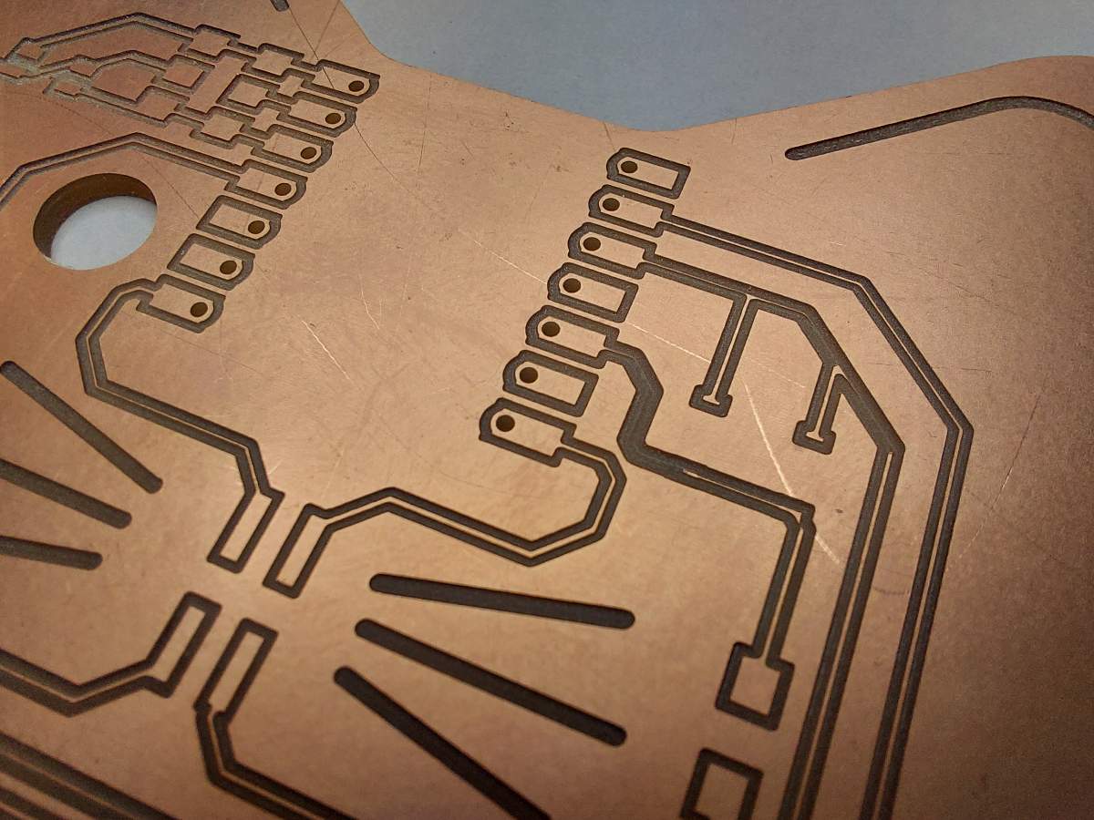
Uneven depth, some tracks cut through
Just right
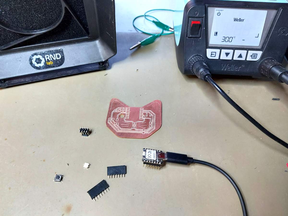
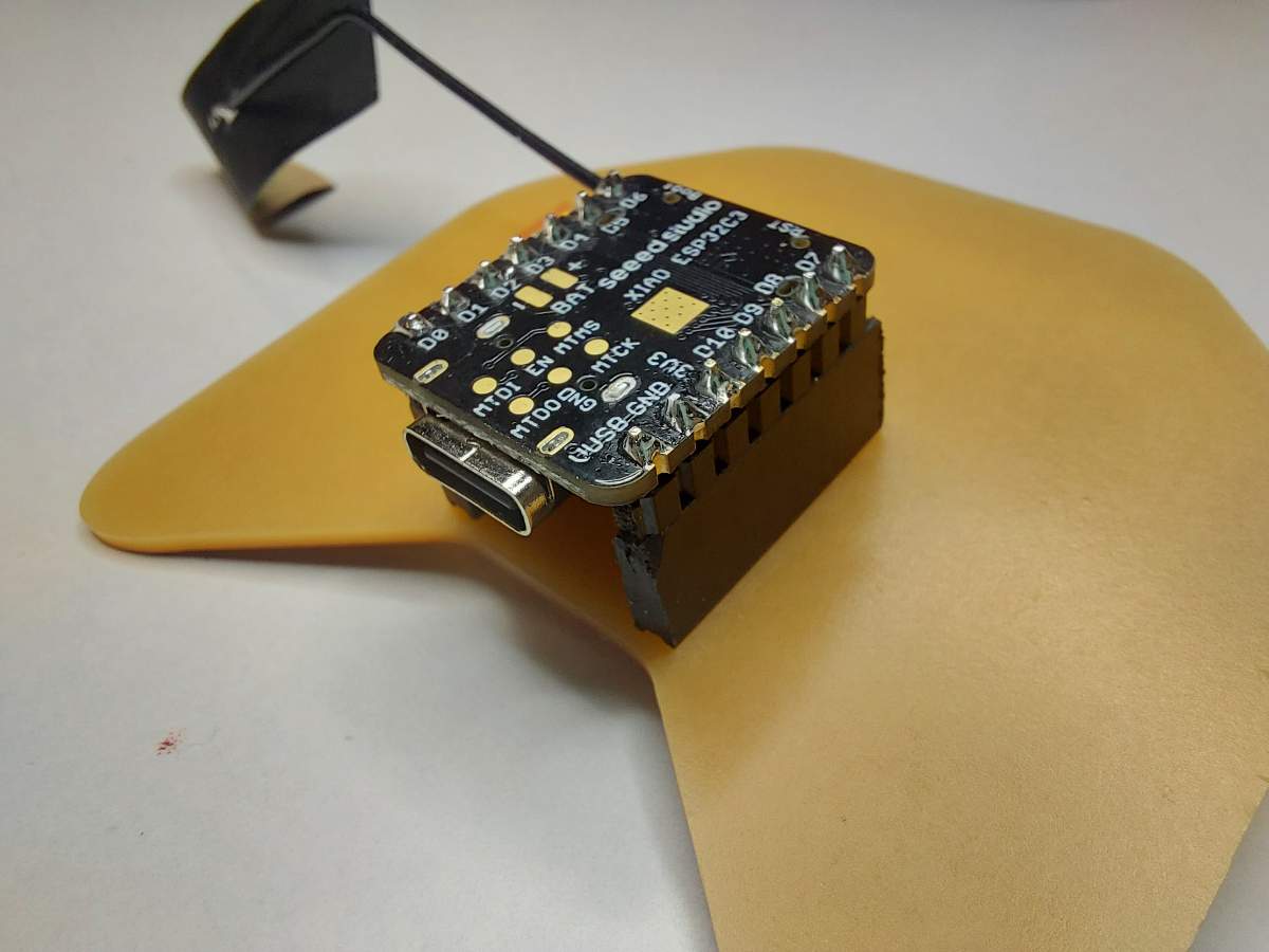
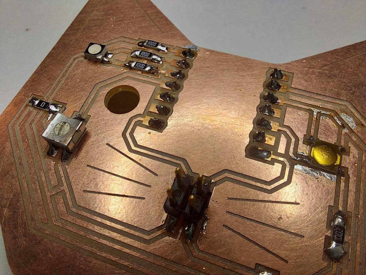
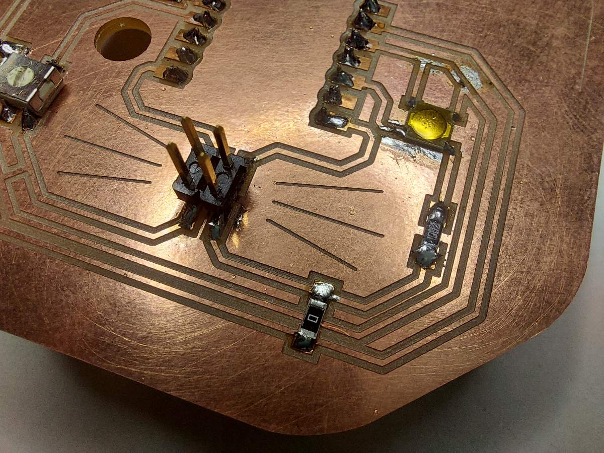
Soldering
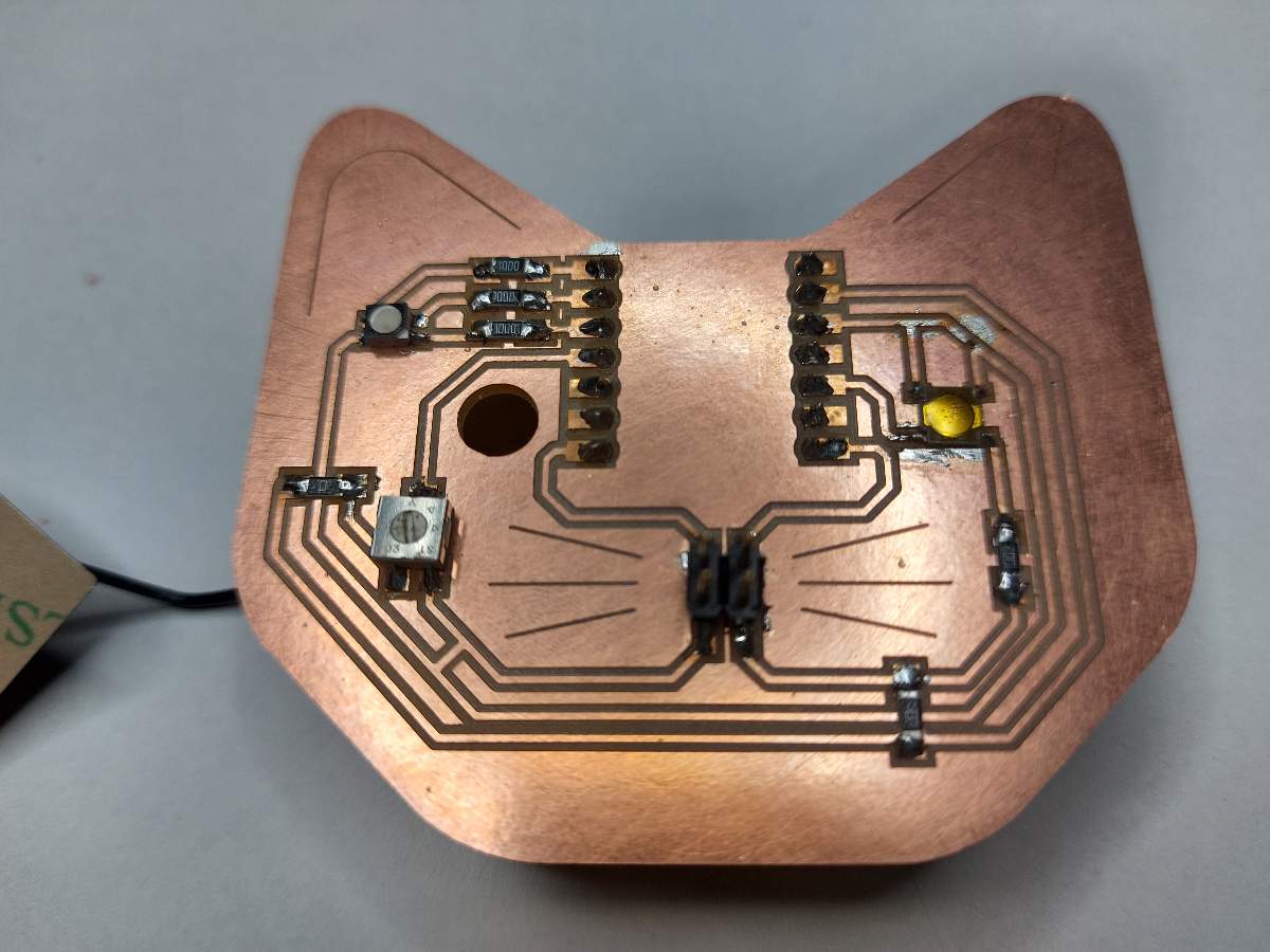
Testing the board
I tested the board out with the updated code I prepared as the Embedded Programming assignment. Pictured below is the board working in the Networking assignment