Computer Controlled Machining
Design of the vinyl roll storage box for CNC milling
Design
- I measured the vinyl rolls intended to be stored in the box and the space available to place it by the vinyl cutter. I also measured the plywood board - it was 120x120x14.5cm
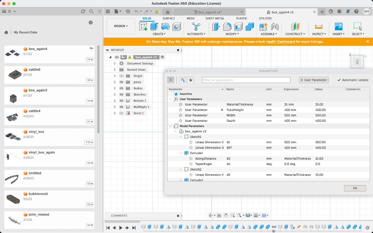
- I set the basic parameters in Fusion360 to be able ot change them later according to possible design iterations
-
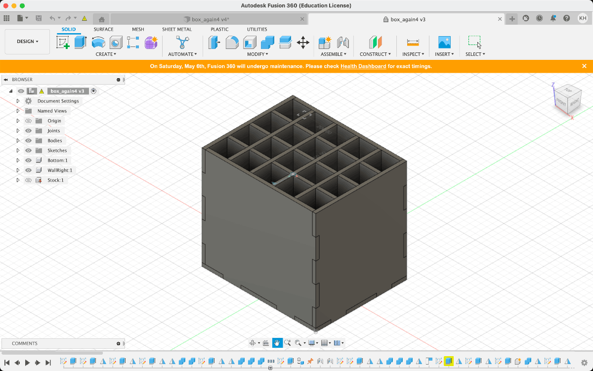
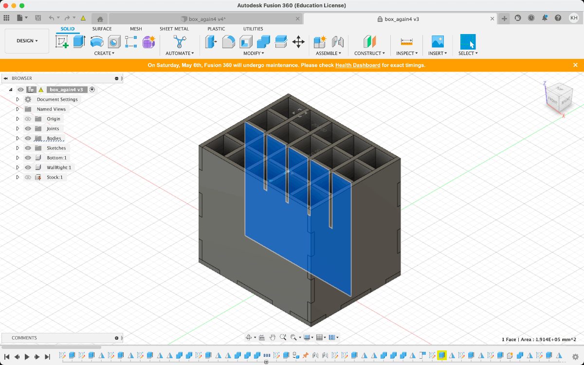
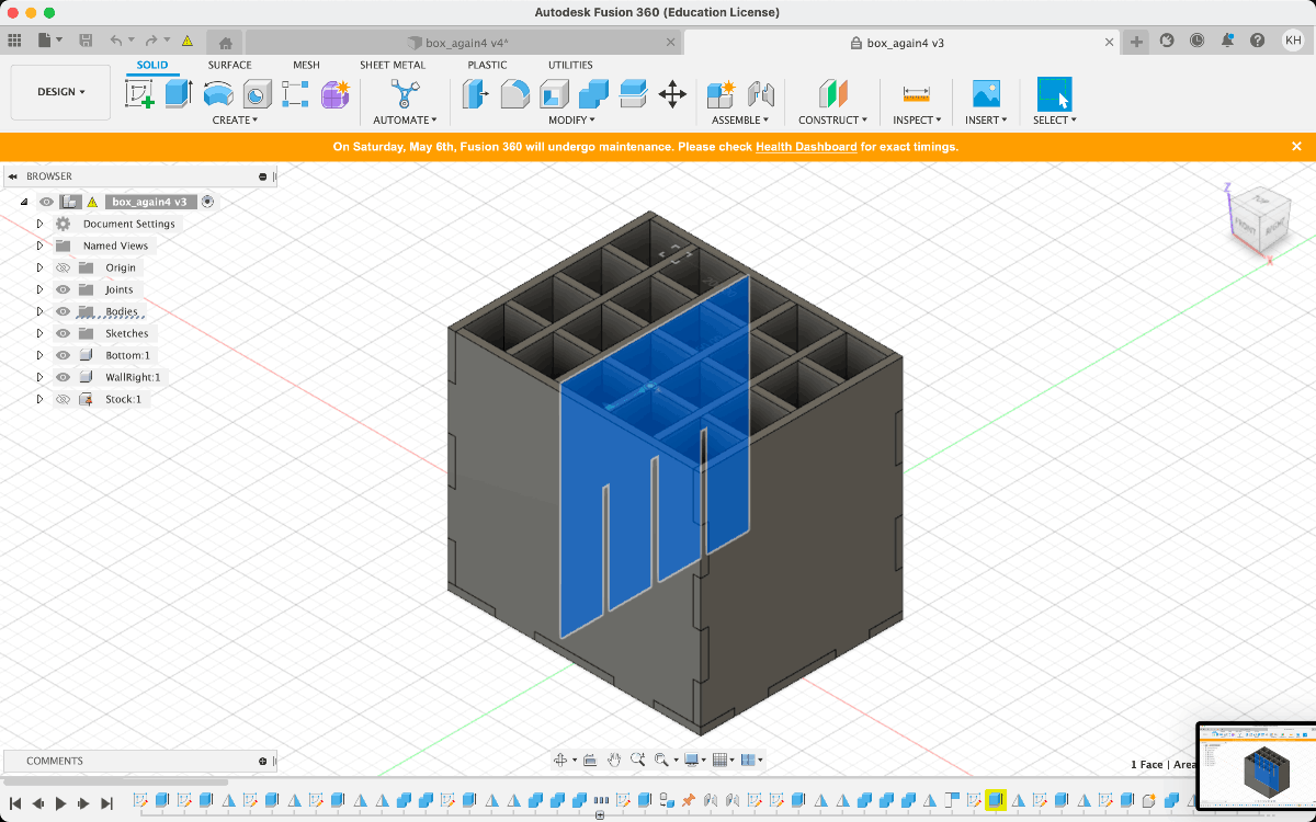
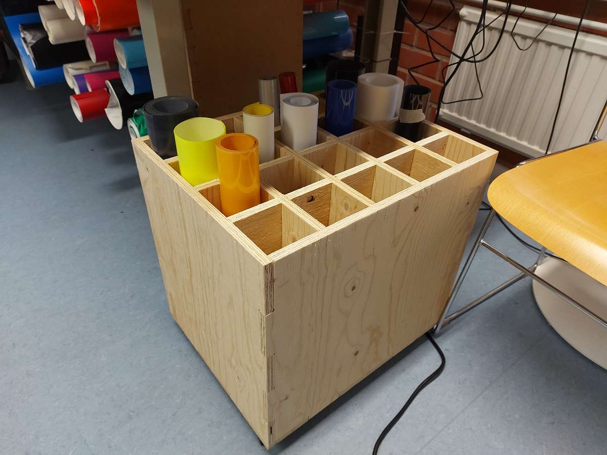
I designed the box pixtured below, with interior divider part separate from the outer box
Nesting for CNC milling
-
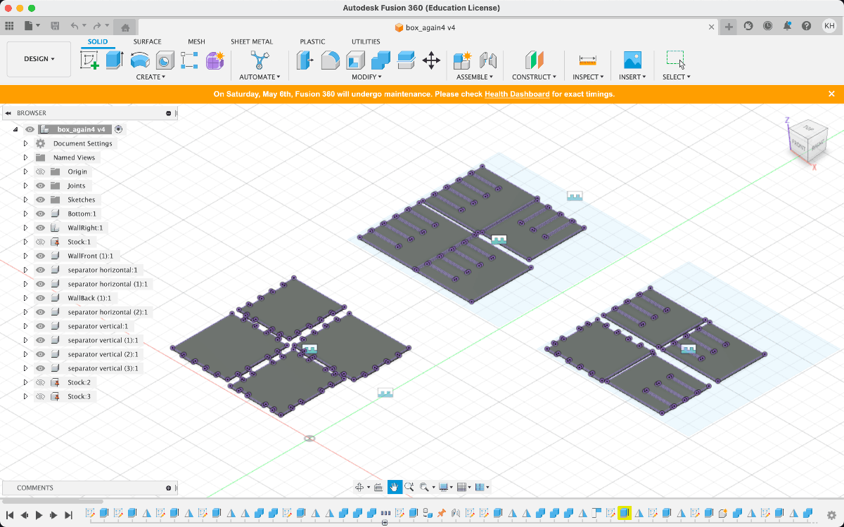
I order to create the toolpaths, I needed ther parts to be laid flat and arranged to fit in the given dimensions. I created a new cube model representing the stock board and Grounded it (locked to the floor plane)
-
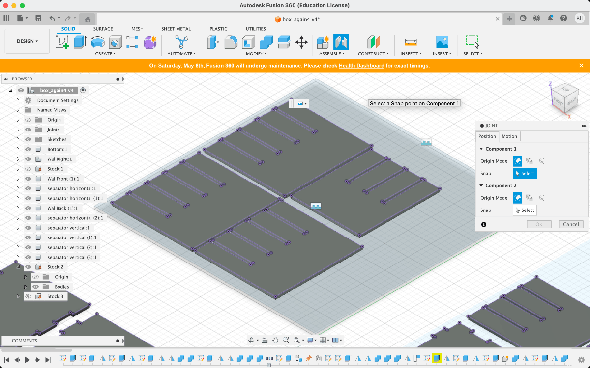
Using the Joint option, I placed all the parts flat on 3 stock boards
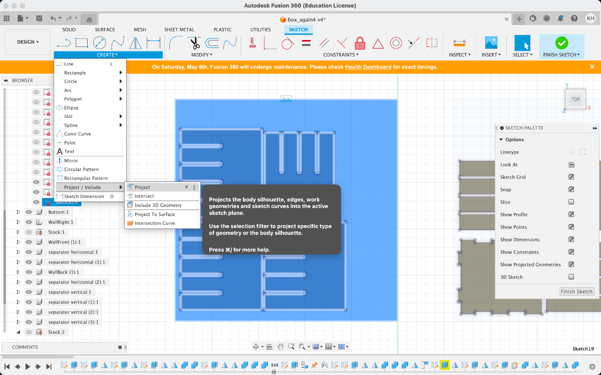
- I created a new Sketch and used the Project option to get my parts as curves
-
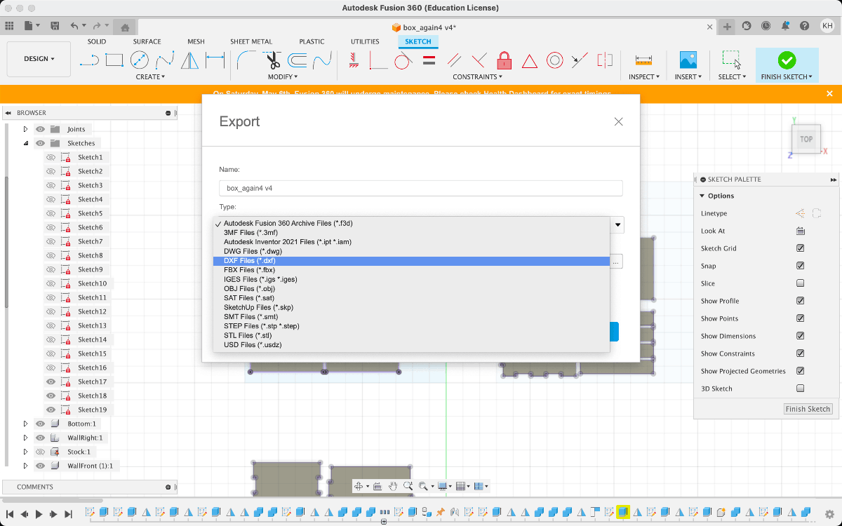
I exported them (each stock as separate file) as .dxf files
Creating the 3D toolpaths in VCarve
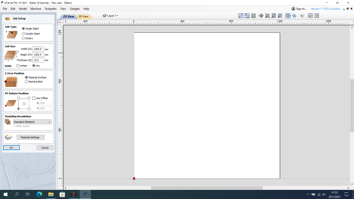
- I imported my .dxf file to VCarve and entered the dimensions of my stock in the Job size tab and set the Z zero position to Material surface option.
- I also set the Datum position to be the south-west (bottom left) vorner.
- Then I arranged the pieces on the stock, leaving sufficient space between them to allow for tabs. I had 3 separate files for 3 boards and loaded them as separate Sheets (they are available in a rather hidden menu on the left most vertical tabs)
-
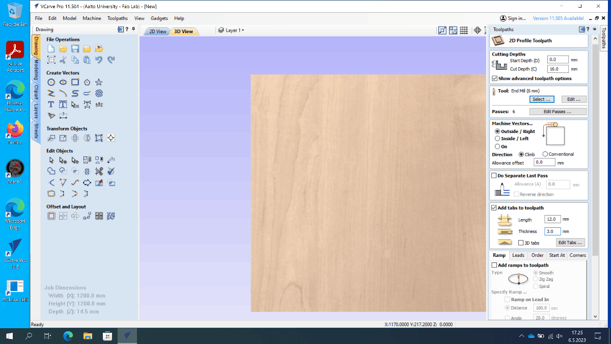
I created a new 2D Pocket toolpath and set the Cut depth to 16mm - the thickness of my stock material + small offset (use only if there is sacrificial layer under the stock)
- I set hte Machine vectors to Outside/right
- I chose the Climb option
as the Direction
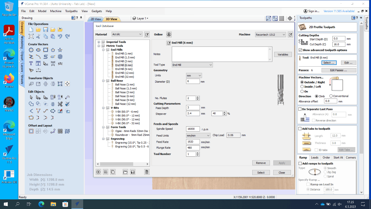
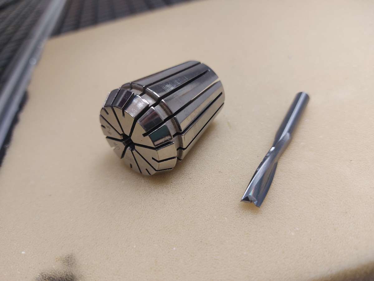
- I proceeded to select the right tool for the job - 6mm flat end, 2 flute, upright cut end mill oriented towards softer materials (with looser helix, contrary to the universal tools)
- I set the Pass depth to be half of the diamter of my tool - 6mm/2=3mm
- I set Stepover to be 40% value of the diameter
- In Feeds and speeds I filled the Spindle speed to 16 000rpm
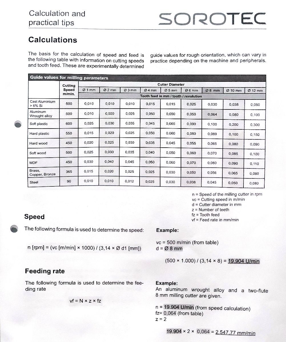
- I looked up the Chip load table for this specific mill given by the manufacturer (this property values among manufacturers)
- The Feed rate was calculated according to the formula
- The value of Plunge rate should be set to 1/4 of the overall Feed rate
- I checked if there are any open curves by Edit>Select>Open curves. There should not be any in the design.
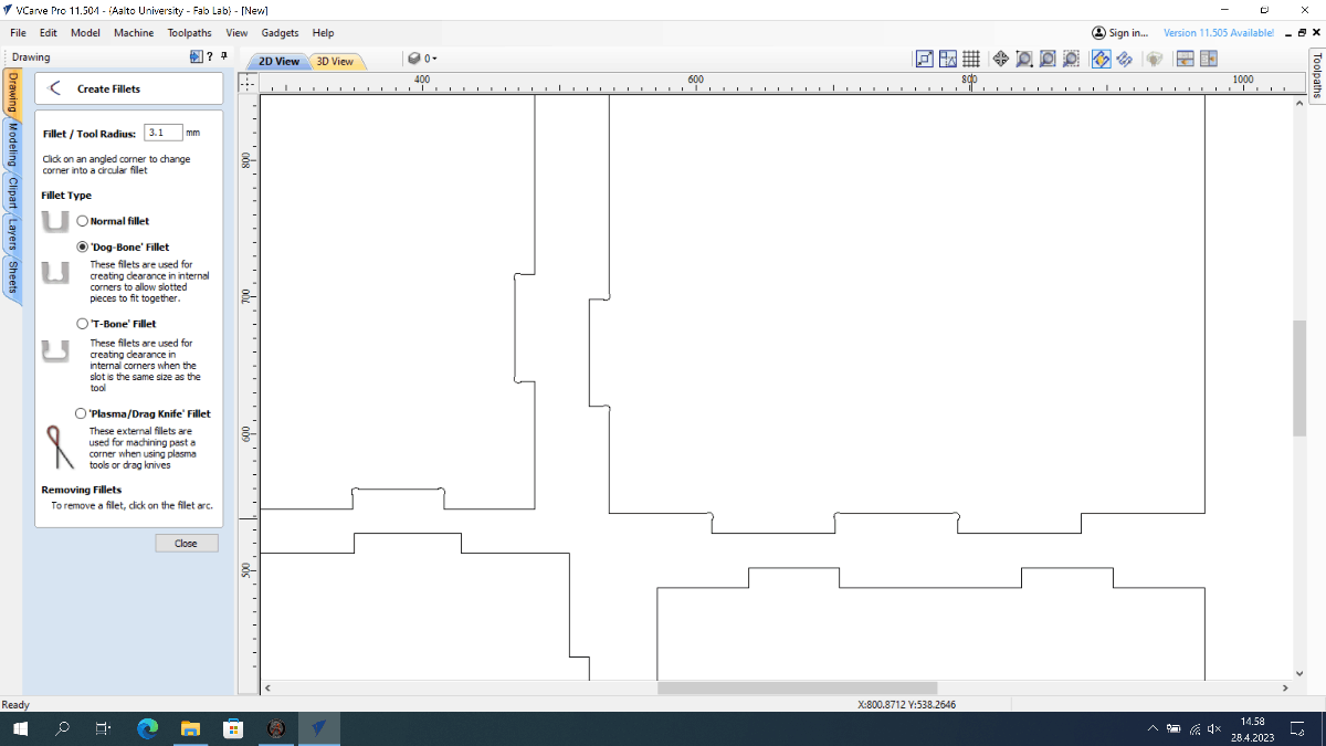
- Then I needed to add so called dog-bones or t-bones, as I needed my joints to fit and the 6mm tool would not be able to cut 90 degresss angle, so I needed to offset that by applying the Fillet option
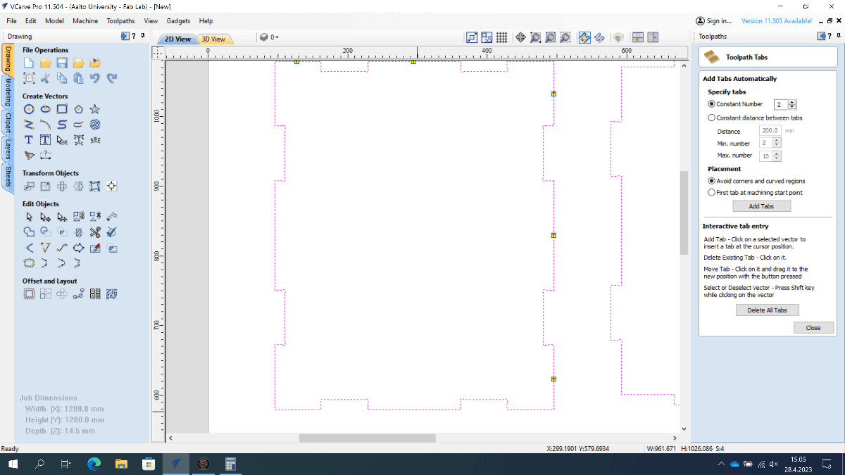
- Then I needed to add tabs - small bridges between the pieces and stock material, that would be left uncut to keep the pieces from moving during the cutting. I set the tabs to me 3mm thick. I opted for manual placement - outer edges of the pieces works best and is the easiest to remove from wood later.
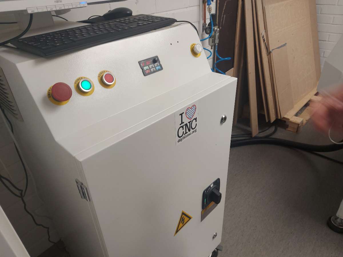
MACH3 and CNC mill setup
- I made sure I adhered to the safety rules regarding use of the machine
- This particular machine is equipped with a vacuum bed, that uses succion to keep the stock fixed during milling. For the learning purposes I aimed to use a more popular method in fab labs - sacrificial layer, meaning an additional board placed under the actual stock that would protect the bed from the tool going too deep.
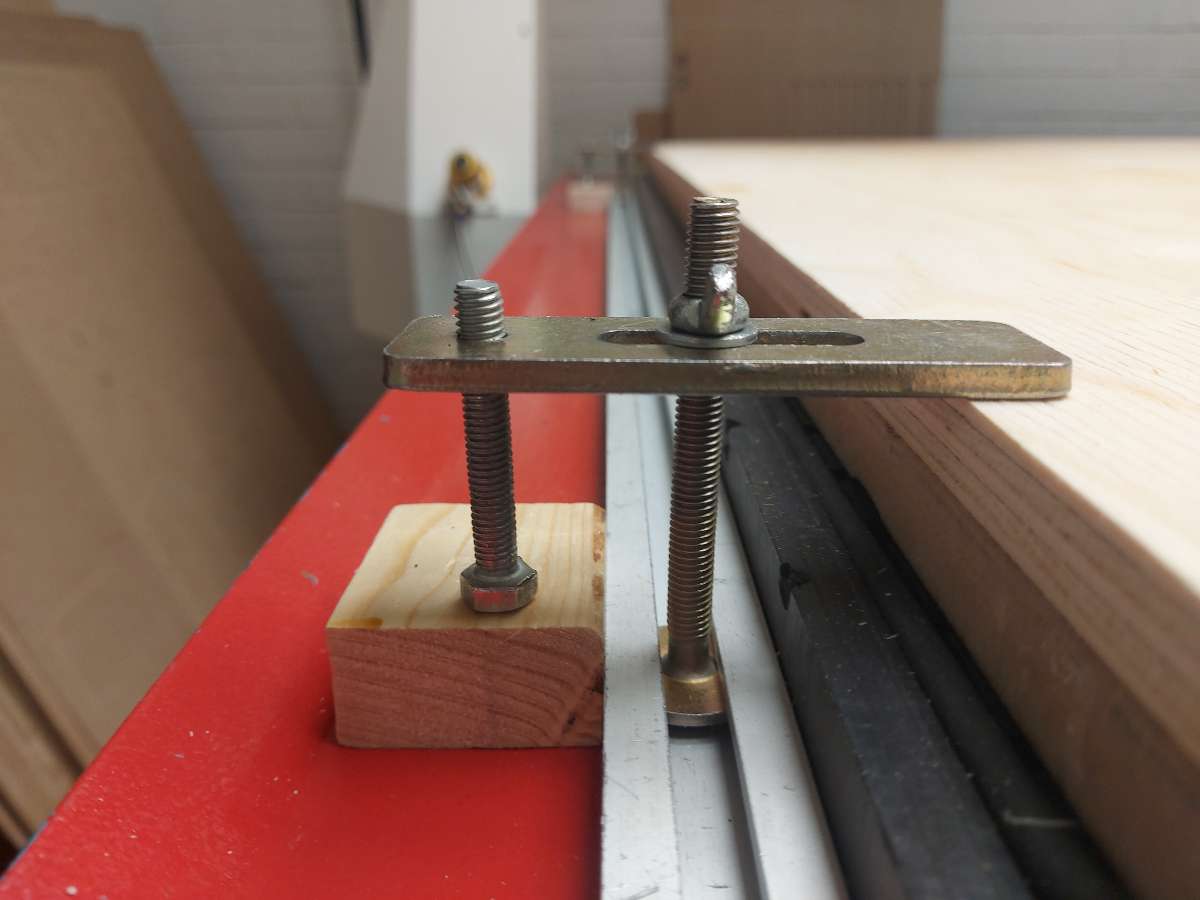
- In order to keep the stock material and the sacrificial layer still I needed to use fixtures. The CNC bed had rails where I inserted t-nuts with bolts and tightened them. I aimed to have them as horizontal as possible and not going over the material more than 1cm
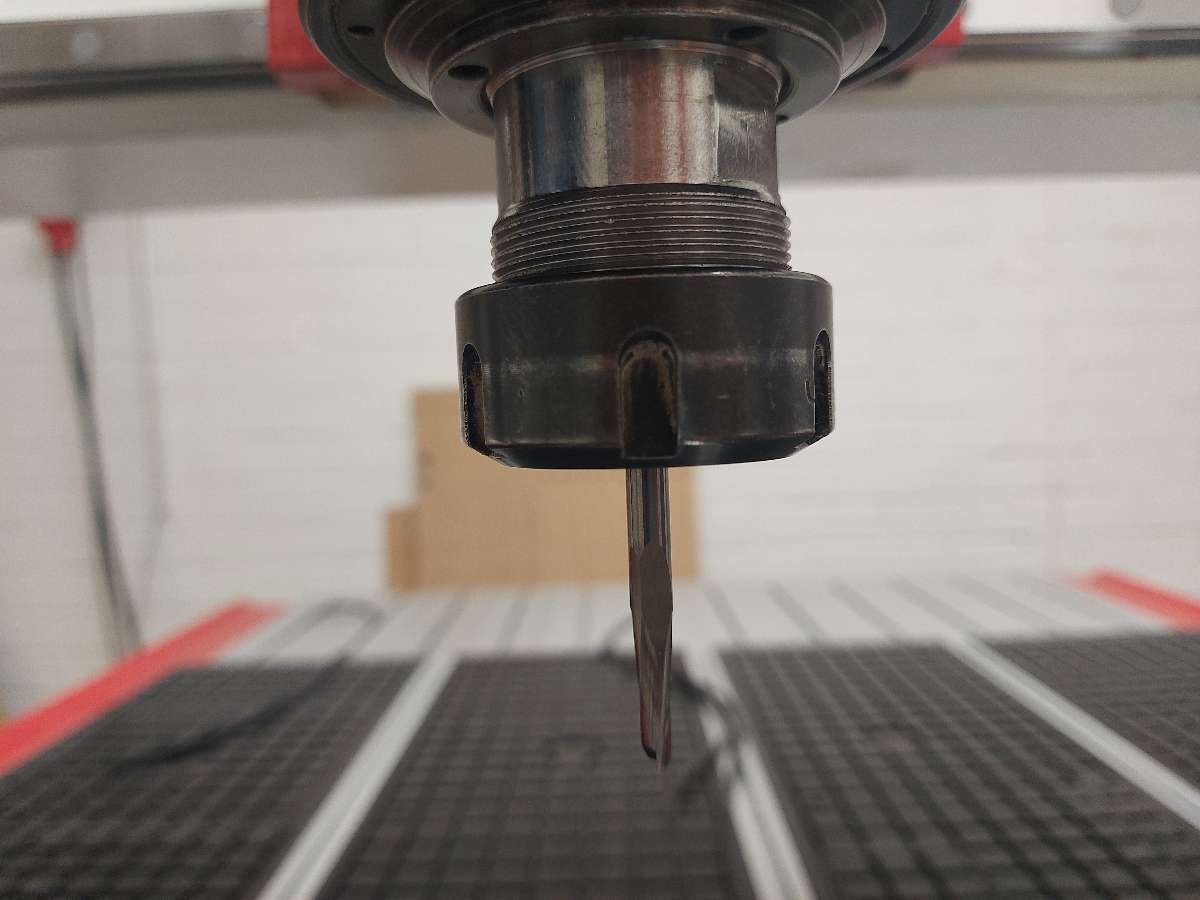
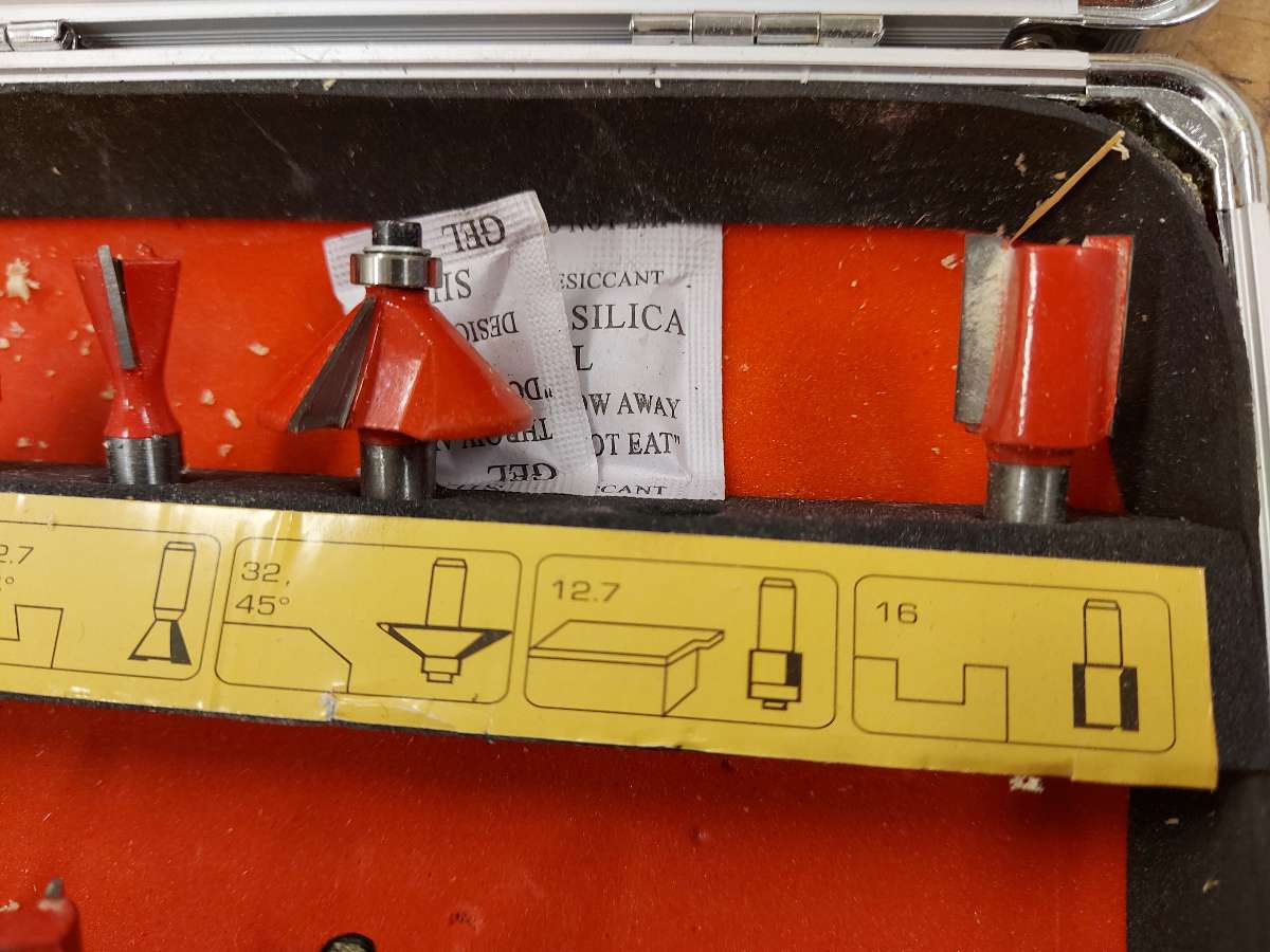
- I installed the milling bit, that I created toolpaths for - a 6mm 2 flute flat head tool intended for use with wood (contrary to the universal tool, intended for harder materials, which has more condensed helix). I selected the fitting 6mm colette, cleaned with air compressor to remove any possible dust remains and installed the tool in. The surface of both should align flat if installed properly.
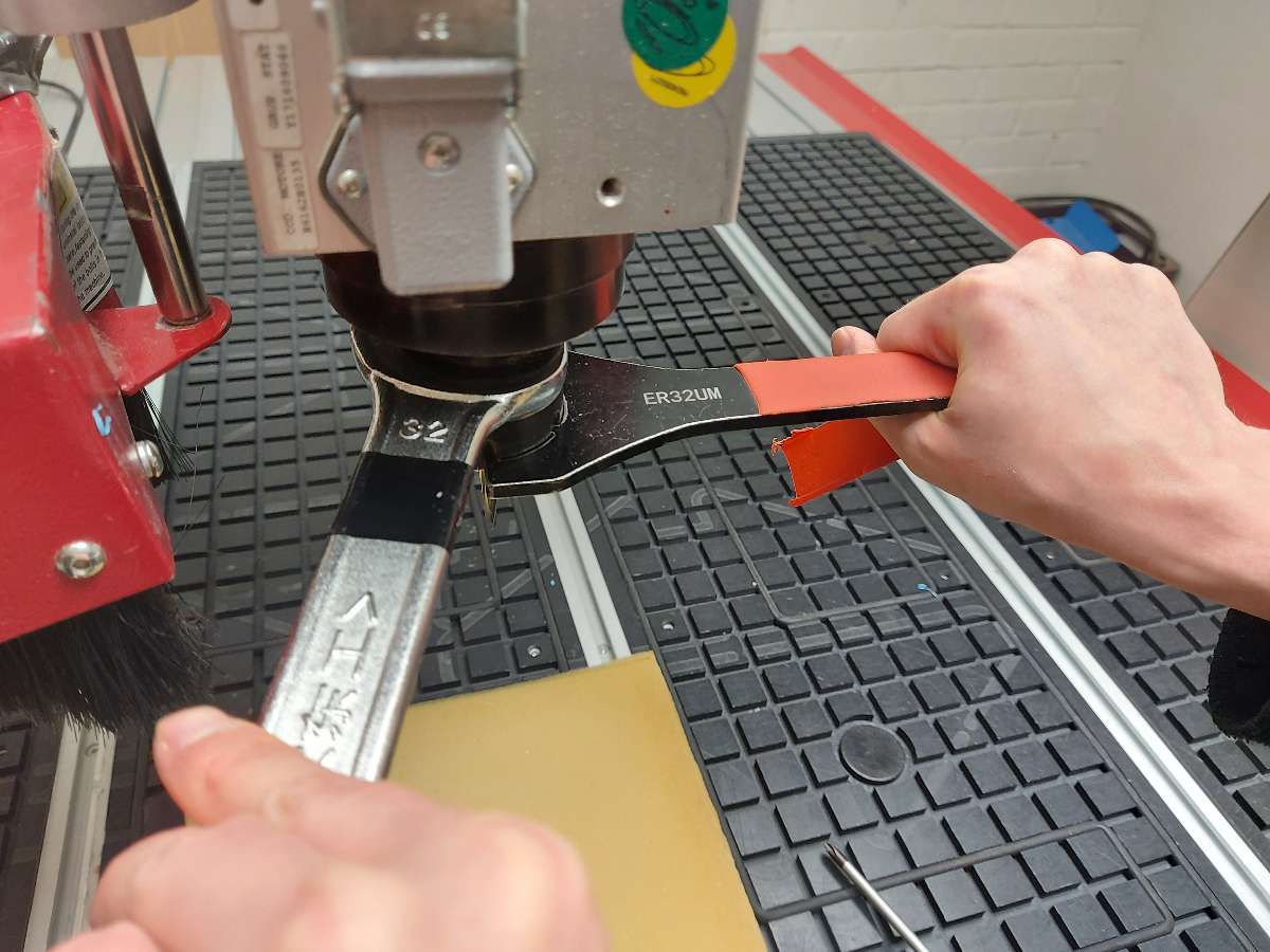
- I placed the colette with the bit in the spindle and fixed it with according tool. Tightening it with force relative to squeezing a lemon was suggested. Watch out for fingers when doing it
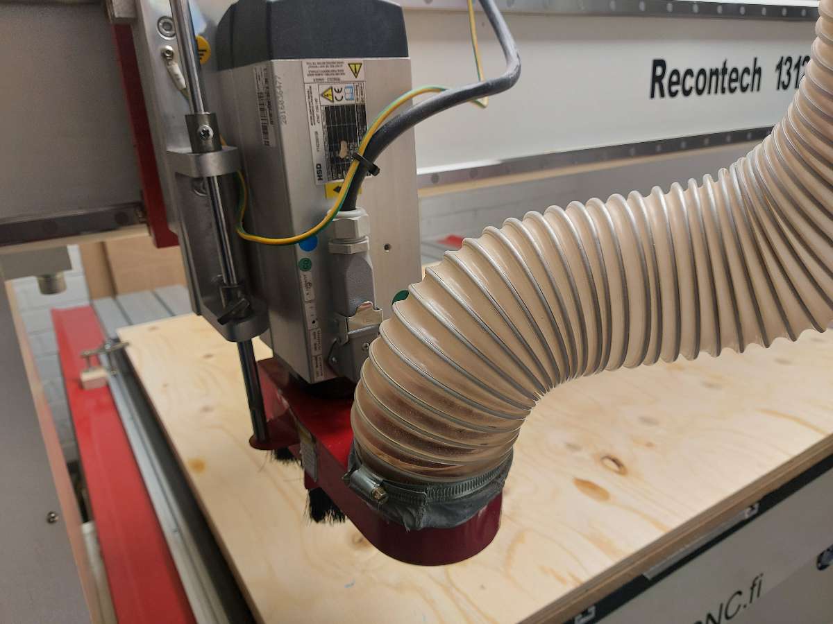
- I put back the dust shoe collecting the dust
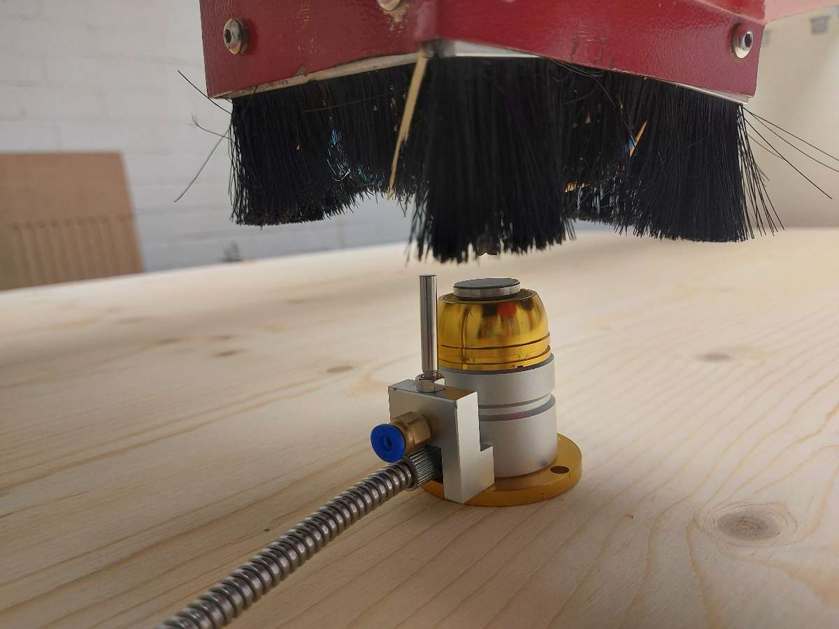
- I turned the machine on and opened the Mach3 software. I loaded the G-codeI clicked Reset and then I made sure the Soft limits was checked. I clicked REF ALL HOME
- Using the software arrow buttons I moved the spindle with tool to the intended XY origin position (south-west corner) and set them in the software
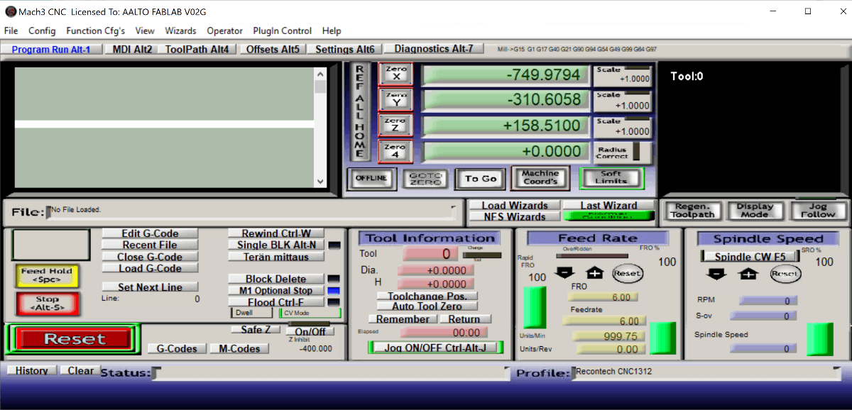
- I placed the designated Z sensor on the bed, right under the tool, made sure the cable was plugged in properly, clicked the mysterious Finnish-only button Teran Mittaus. The machine set the z origin point this way.
- I left the CNC room an using the buttons placed outside - green one started the milling process. For safety I stayed by the machine the whole time is was running
- When the milling finished I could remove the colette with the bit from the spindle using the same tools as before.
- I released the fixtures and could remove the stock from the bed - the best way was to slide it flat towards the front of the machine and then gently flip it horizontally. This way the tabs don't break and keep the pieces in place
- I cleaned the space, machine and tools with a vacuum cleaner
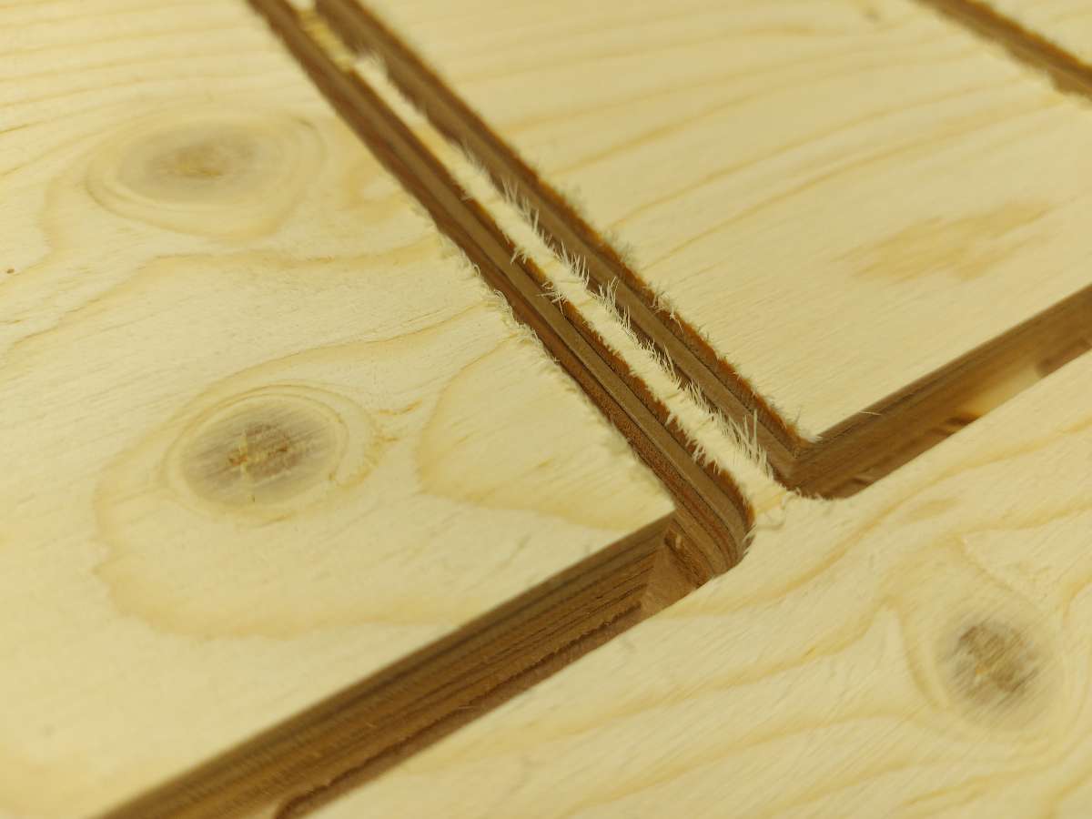
Finishing and assmebly
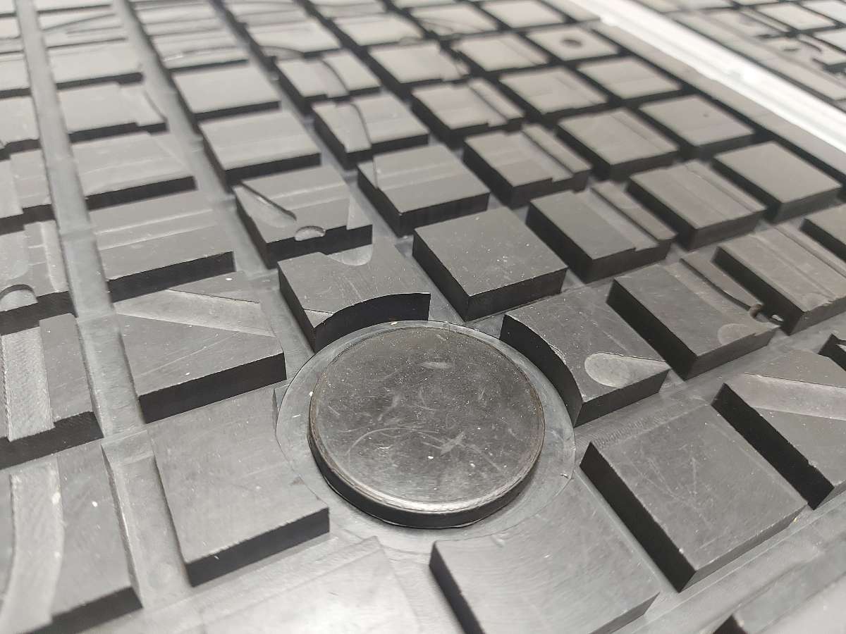
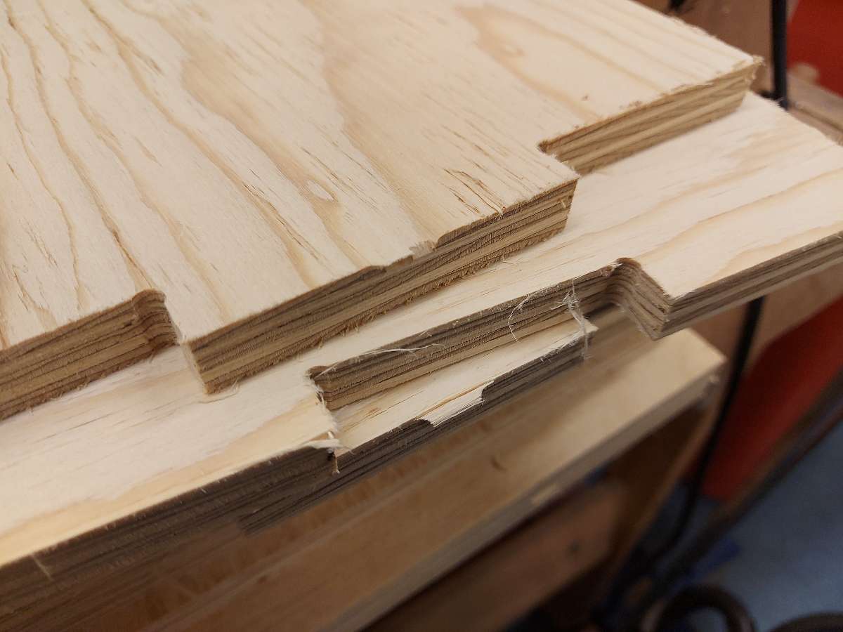
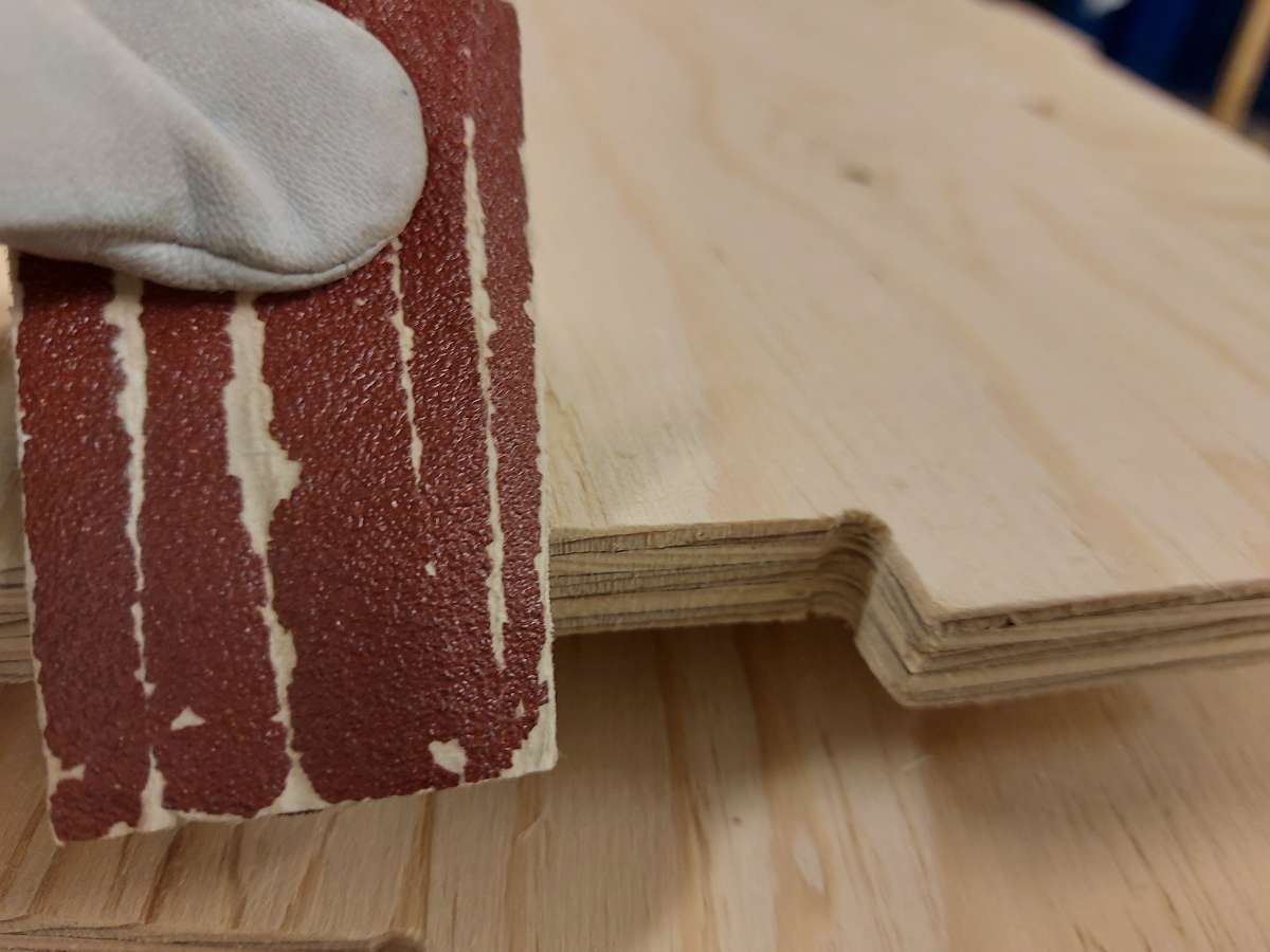
- Close-up of the edges of the pieces right after milling
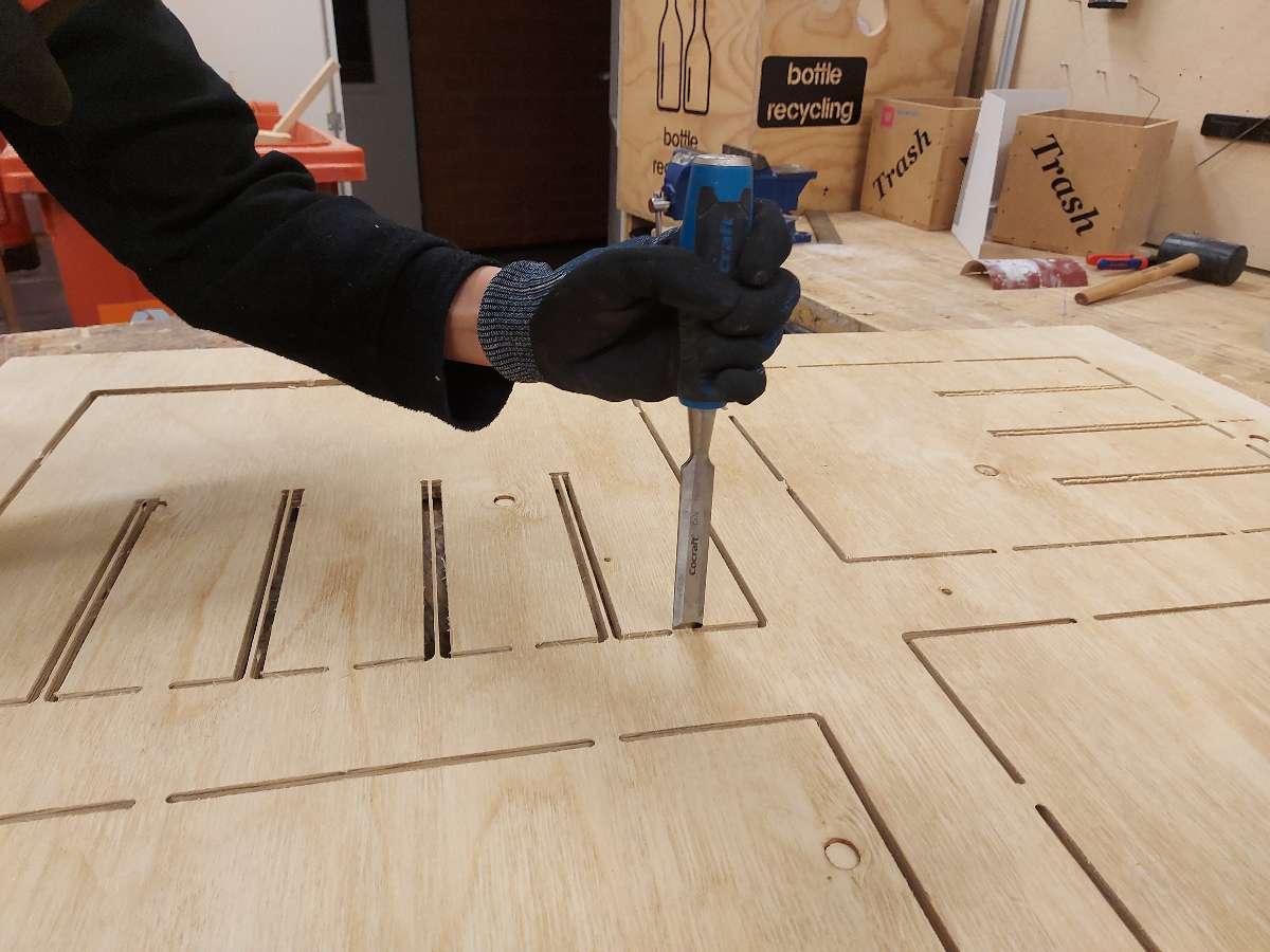
- I placed the stock material flat on a table and used a chisel with a hammer to hit and break the remaining tabs and remove the pieces from the stock
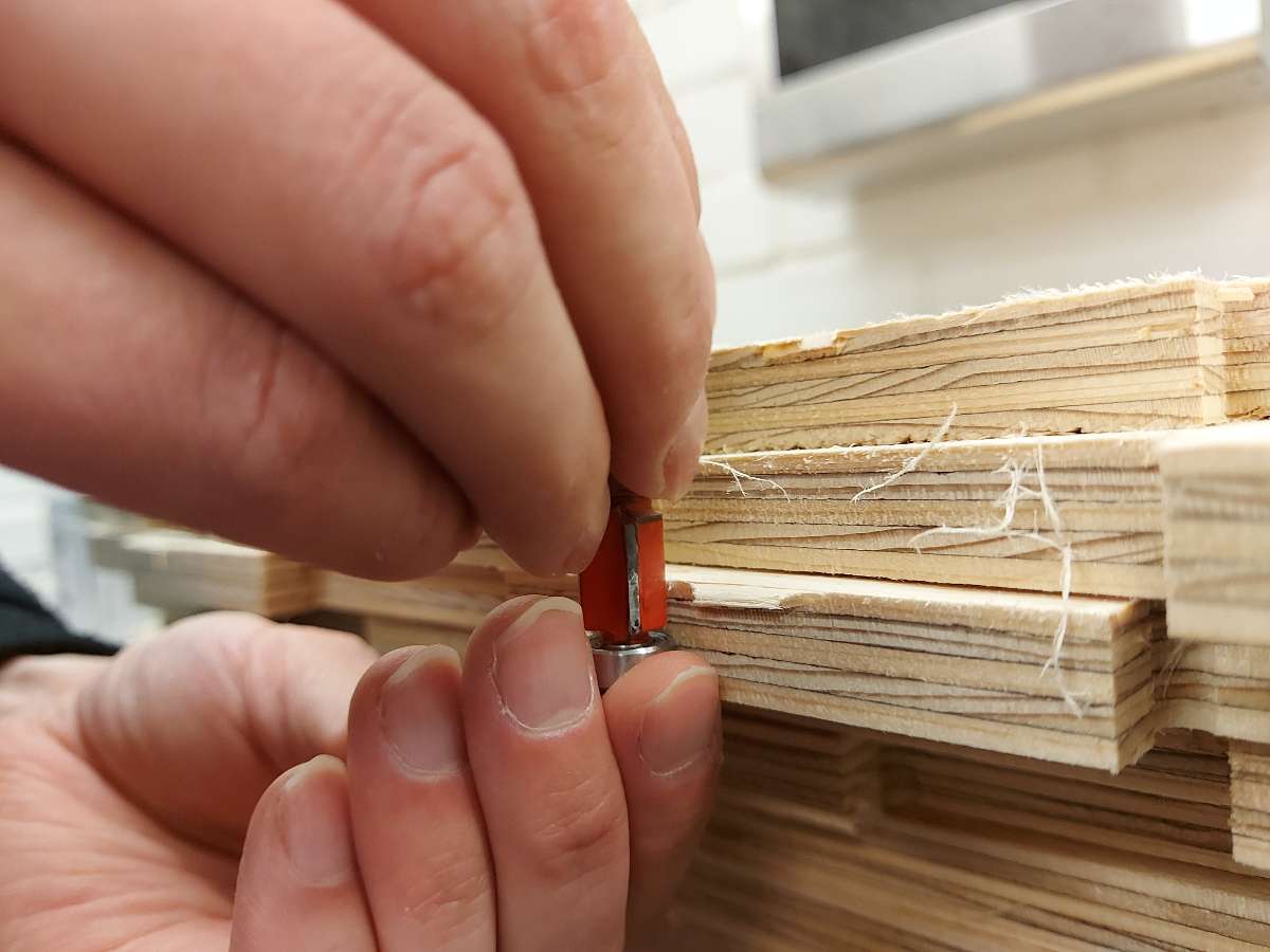
- There were still remains of the tabs on the pieces. I used a designated tool moving vertically along the edges to remove them
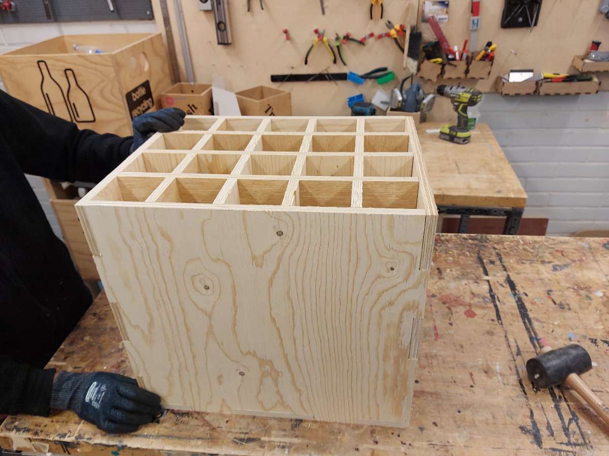
- I used sanding paper to finish all the edges of my pieces and then could proceed to assemble the pieces together. Very satisfying process, especailly with the use of rubber hammer
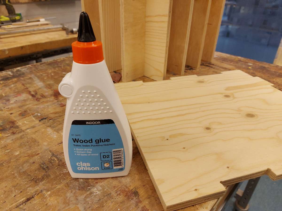
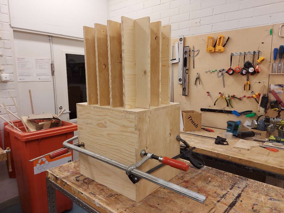
- As the pieces fit slightly loose I applied wood glue to the edges, fixed with clamps and left it to cure
-
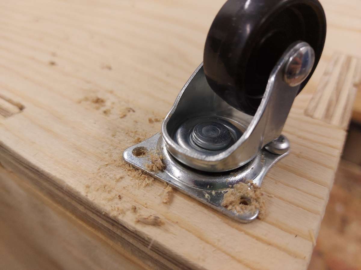
Almost ready, I installed wheels for easy moving
- One of the design requirements for the vinyl roll storage box was the feature of "kickability". Test was perfomed and the box passed it successfully
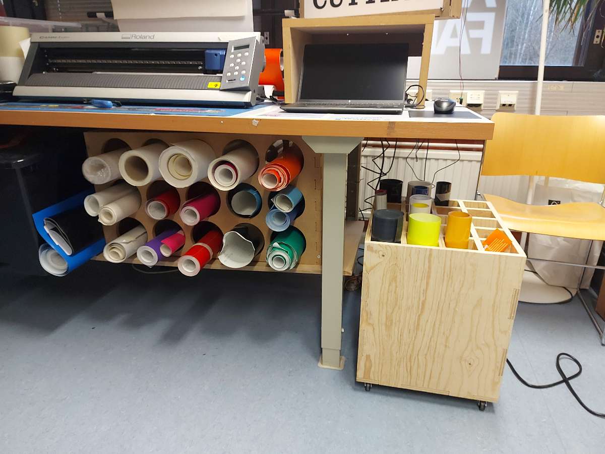
- The box in its final destination performing its job.