13. Embedded Networking and Communications
Learning outcomes
- Demonstrate workflows used in network design
- Implement and interpret networking protocols and/or communication protocols
Objectives
- Link to the group assignment page
- Document your project and what you have learned from implementing networking and/or communication protocols.
- Explain the programming process(es) you used.
- Outline problems and how you fixed them.
- Include design files (or linked to where they are located if you are using a board you have designed and fabricated earlier) and original code.
- Included a ‘hero shot’ of your network and/or communications setup
Link to the group assignment page
https://fabacademy.org/2021/labs/vancouver/students/terrence-carew/assignments/week13g.html
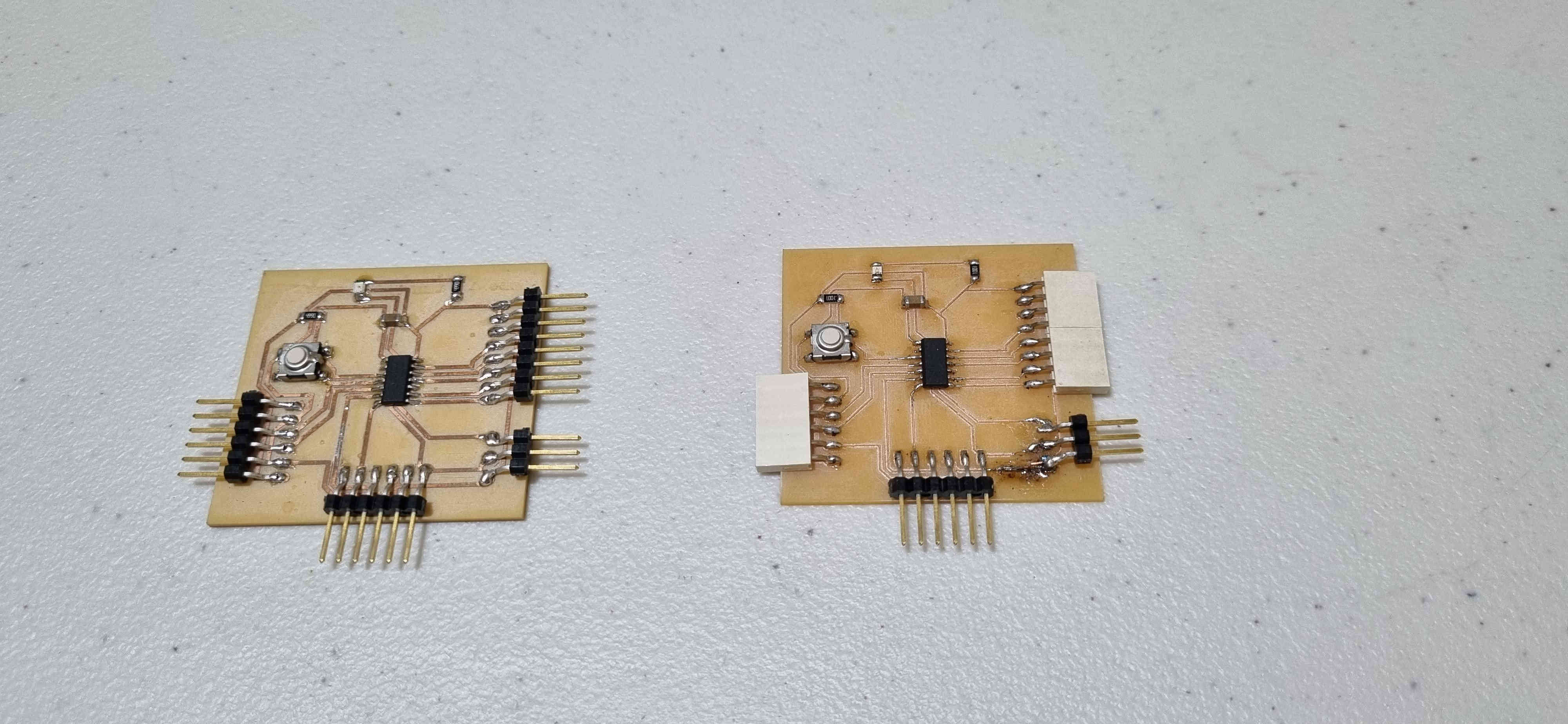
This weeks assignment included reproducing one of the boards I used for the input and output devices week.

I had a look at one of the fab academy student assignment for this week in order to get a better understanding of what is required for the assingment.
https://fabacademy.org/2020/labs/leon/students/adrian-torres/week14.html
I then looked at a couple of online tutorials related to the I2C communication protocol.
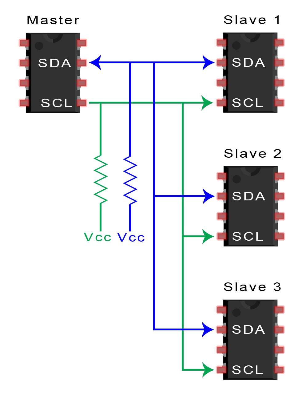
What is I2C
I2C stands for Inter-Integrated Circuit. It is a communication protocol used for transmitting data between microcontrollers or between microcontrollers and other peripherals. I2C uses two bidirectional lines: Serial Data Line (SDA) and Serial Clock Line (SCL). It is a master-slave protocol, which means that one device acts as the master and initiates the communication, while the other device acts as the slave and responds to the master’s requests. I2C is commonly used in embedded systems, such as sensors, LCDs, and EEPROMs, due to its simplicity and versatility.
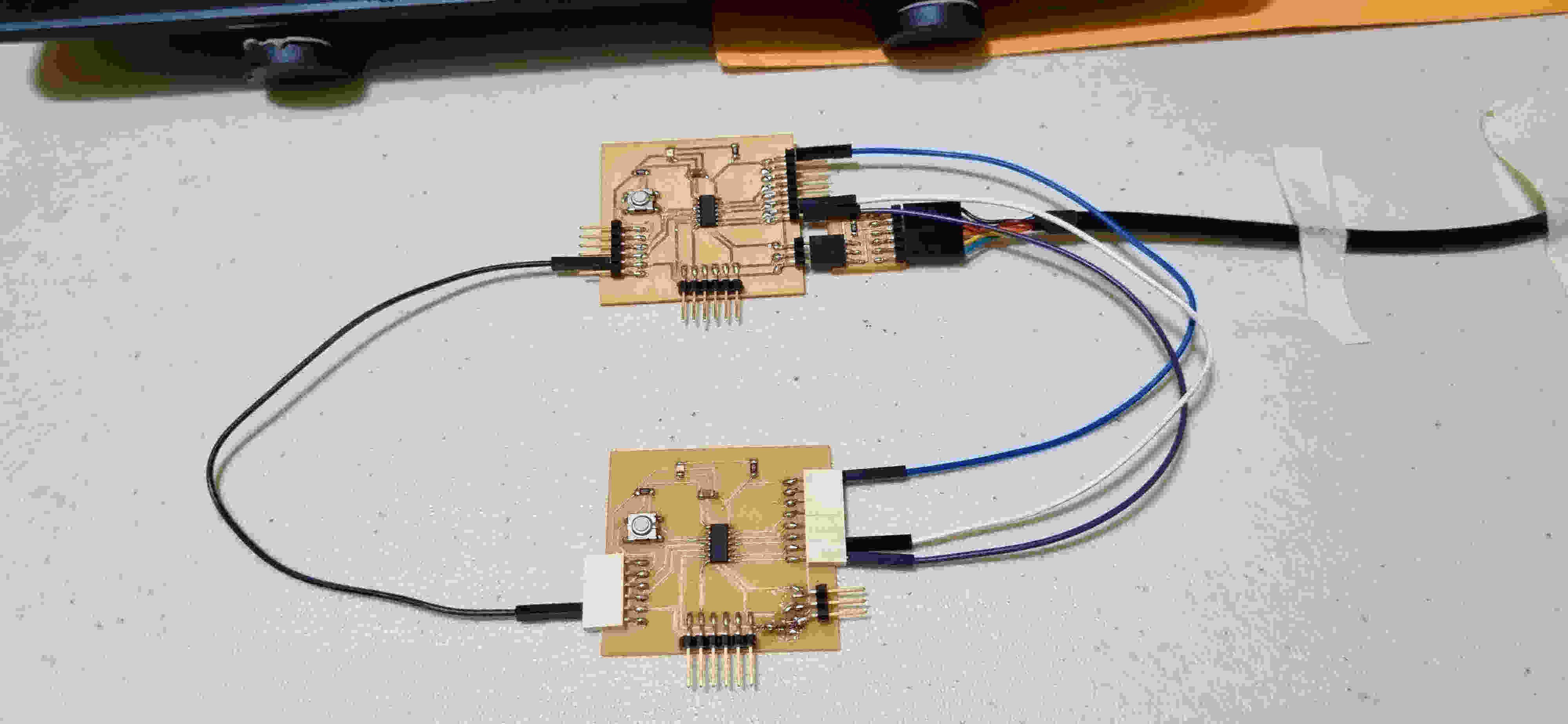
The two microcontrolled boards used for the assignment are shown below.
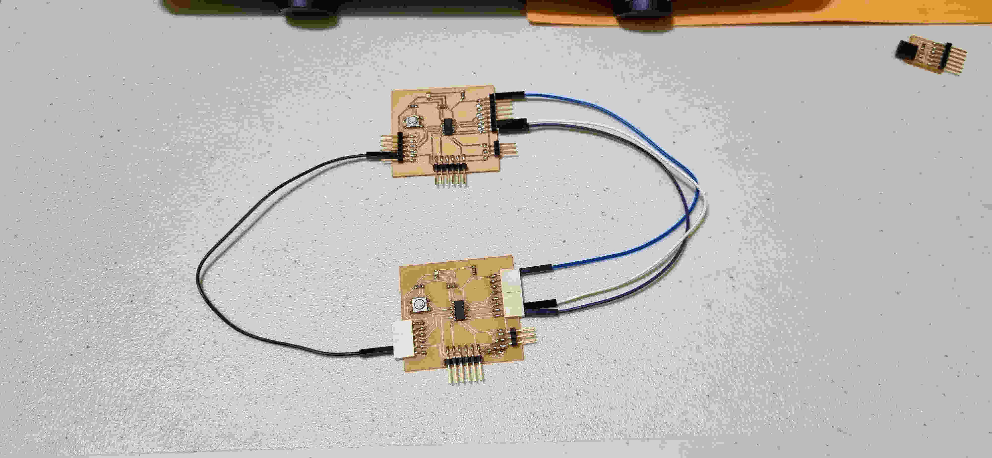
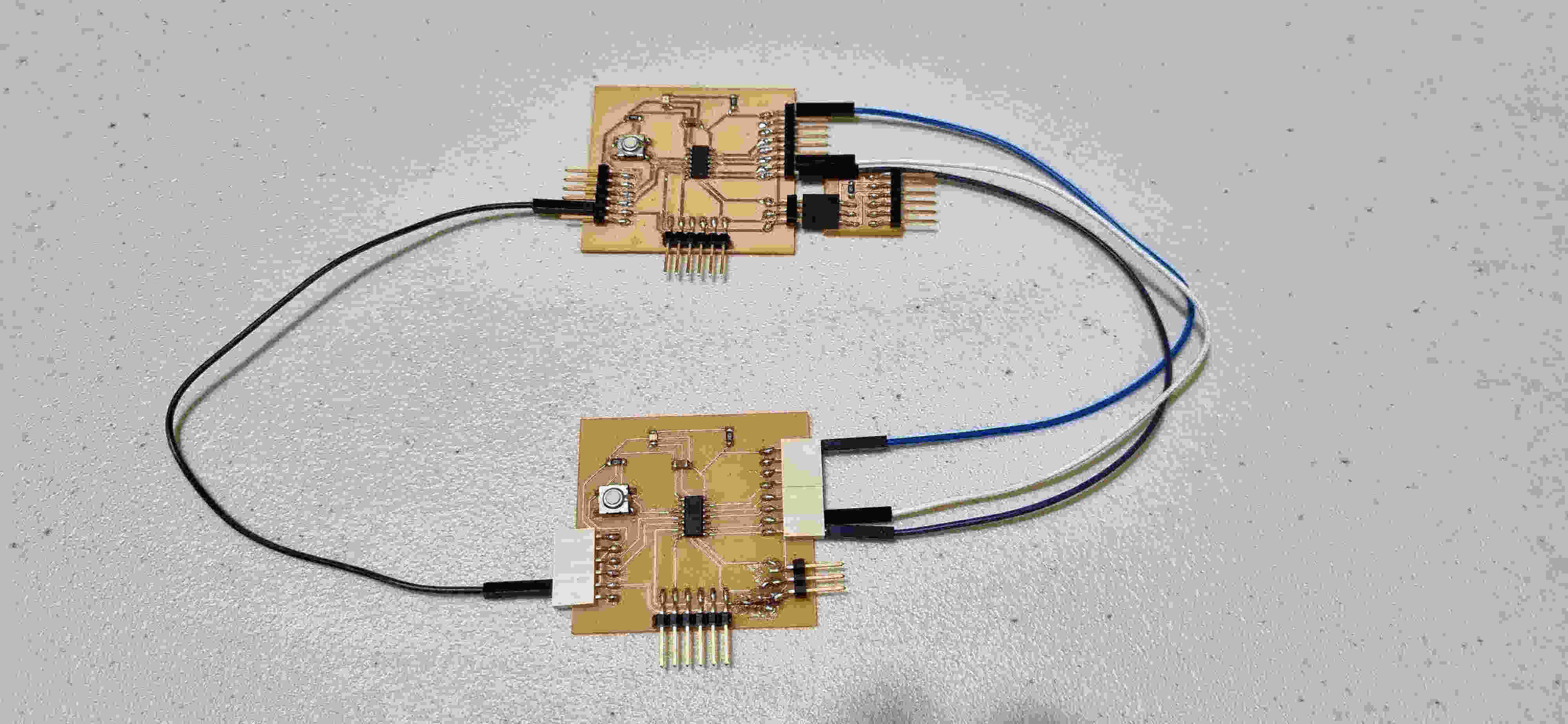
The next image shows how the boards were connected to communicate. The following connections were made:
-
pin8 on the attiny1614 to pin8 on the other attiny1614.
-
pin9 on the attiny1614 to pin9 on the other attiny1614.
-
A commom groung between the two attiny 1614 microcontroller boards
-
vcc to vcc
I used code from the following website and made relevant changes in the code to match the connections of my microcontroller boards.
https://www.tinkercad.com/things/8pFx35ByTCT-arduino-i2c-1-master-2-slave
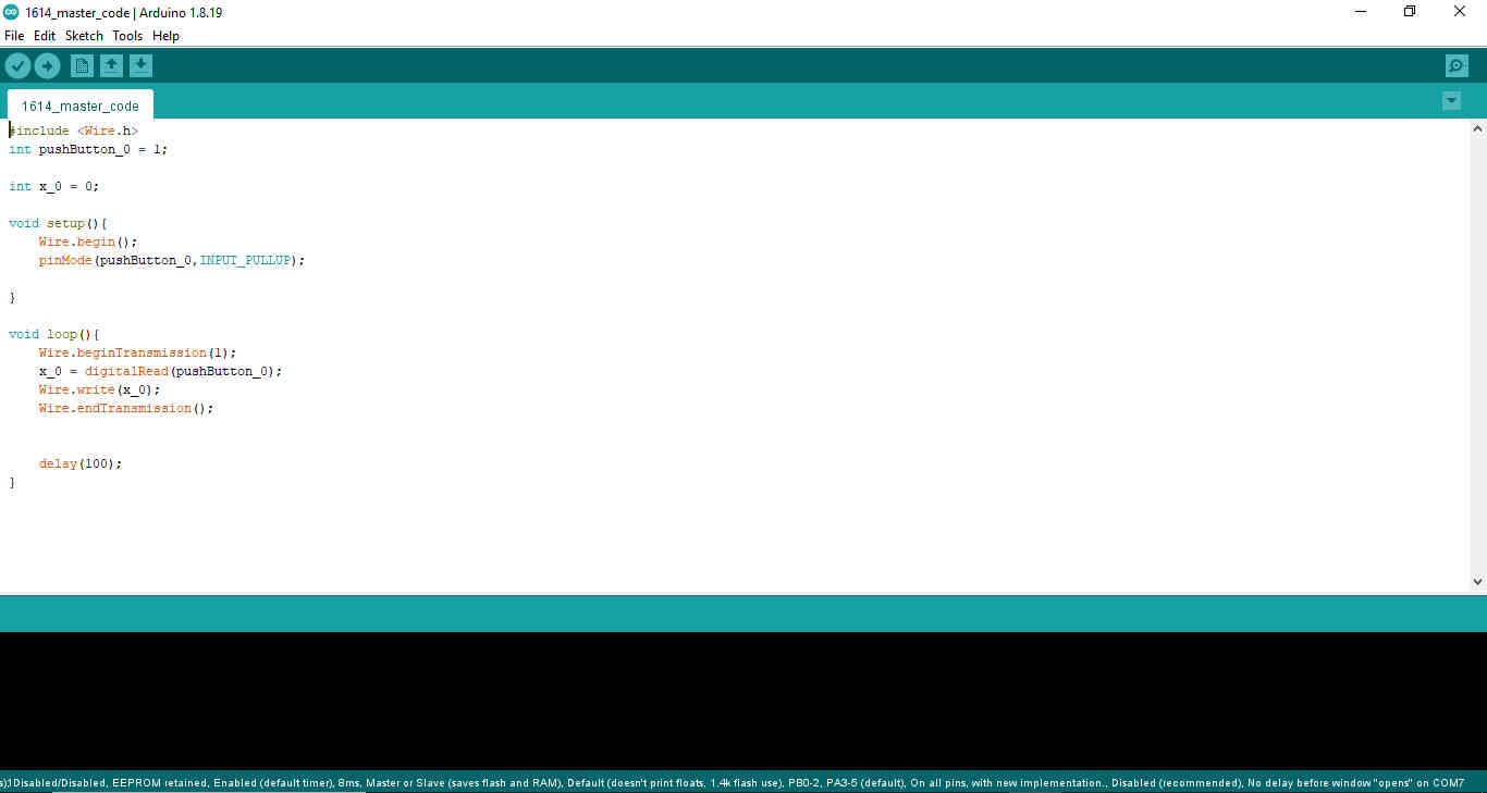
Code used for the master
Use the three backticks to separate code.
#include <Wire.h>
int pushButton_0 = 1;

int x_0 = 0;

void setup(){
    Wire.begin();
    pinMode(pushButton_0,INPUT_PULLUP);

}

void loop(){
    Wire.beginTransmission(1);
    x_0 = digitalRead(pushButton_0);
    Wire.write(x_0);
    Wire.endTransmission();


    delay(100);
}
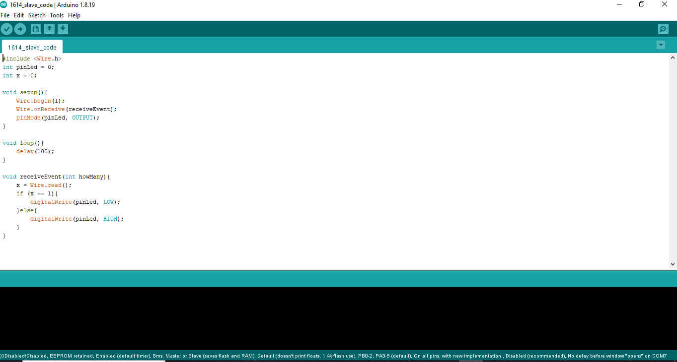
Code used for the slave
#include <Wire.h>
int pinLed = 0;
int x = 0;

void setup(){
    Wire.begin(1);
    Wire.onReceive(receiveEvent);
    pinMode(pinLed, OUTPUT);
}

void loop(){
    delay(100);
}

void receiveEvent(int howMany){
    x = Wire.read();
    if (x == 1){
        digitalWrite(pinLed, LOW);
    }else{
        digitalWrite(pinLed, HIGH);
    }
}

Networking and Communications
Original Design files and source code
References
https://deepbluembedded.com/i2c-communication-between-two-arduino/
https://www.tinkercad.com/things/8pFx35ByTCT-arduino-i2c-1-master-2-slave
https://www.circuitbasics.com/basics-of-the-i2c-communication-protocol/