2. Computer Aided design
Learning outcomes
- Evaluate and select 2D and 3D software
- Demonstrate and describe processes used in modelling with 2D and 3D software
Objectives
- Model experimental objects/part of a possible project in 2D and 3D software
- Show how you did it with words/images/screenshots
- Include your original design files
This week assignment comprised of researching and using 2D and 3D software.
Research
During my research i reviewed a tutorial from the following website.
https://pub.fabcloud.io/tutorials/week02_computer_aided_design/2d_tools.html
I also looked at different CAD Software such as AutoCAD,Gimp,Krita,Corel Draw and Fusion 360.
What is CAD software?
CAD, or computer-aided design and drafting (CADD), is technology designed for creators to design, draft, and produce technical documentation—replacing manual hand-drawn and drafting techniques with a digital first process. Whether you’re an architect, designer, or engineer, you’ve probably used 2D or 3D CAD programs such as AutoCAD, AutoCAD LT, Civil 3D, Inventor, or Fusion 360 software. These widely used tools can help you explore design concepts, visualize with photorealistic renders, and simulate real-world performance.
Inkscape was used for 2D Software
I downloaded inscape from the following website:
What is inkscape
Inkscape is a free open source vector graphics editor.The main format it uses is SVG(scalable vector graphics) It is mainly used for creating art and illustrations related to things such as clip art logos and flowchart diagrams.
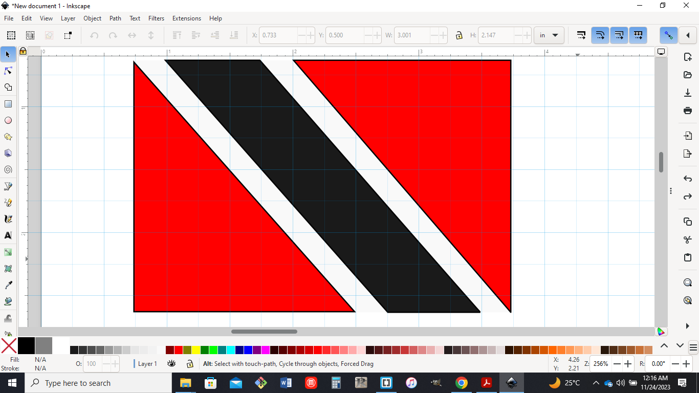
I decided to use some basic shapes to create the national flag of Trinidad and Tobago.
Step 1
I started inkscape and it opened up with a window and a default page size.
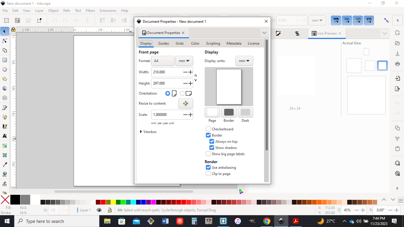
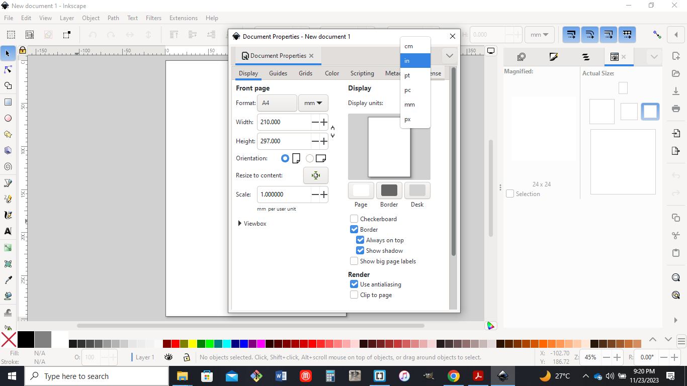
I increased the size of the window and changed the units to inches as shown in the image below.(file > document properties > inches)
Step 2
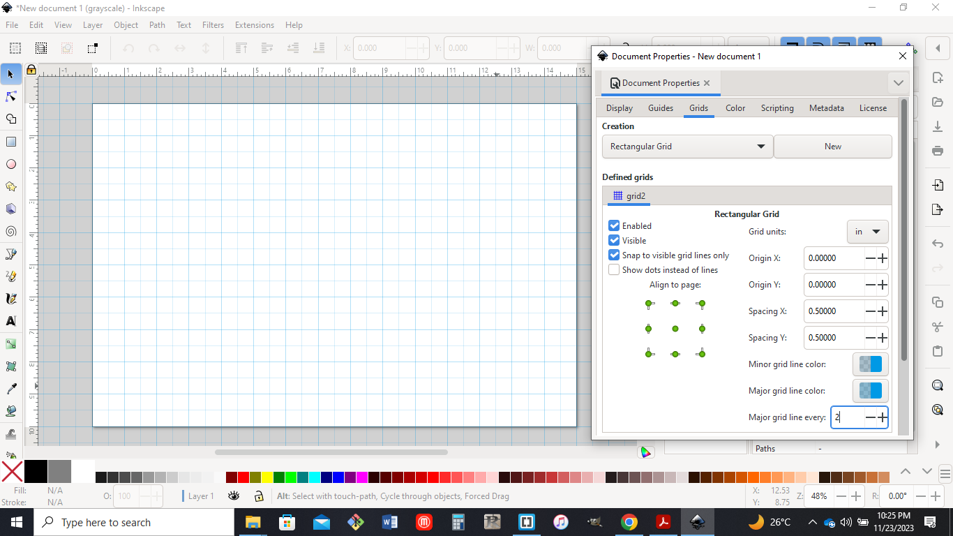
I then set my page size to a desired size to draw the flag which was 15in x10in.I also set the X and Y spacing on the grid of the page to be 0.5in.
Step3
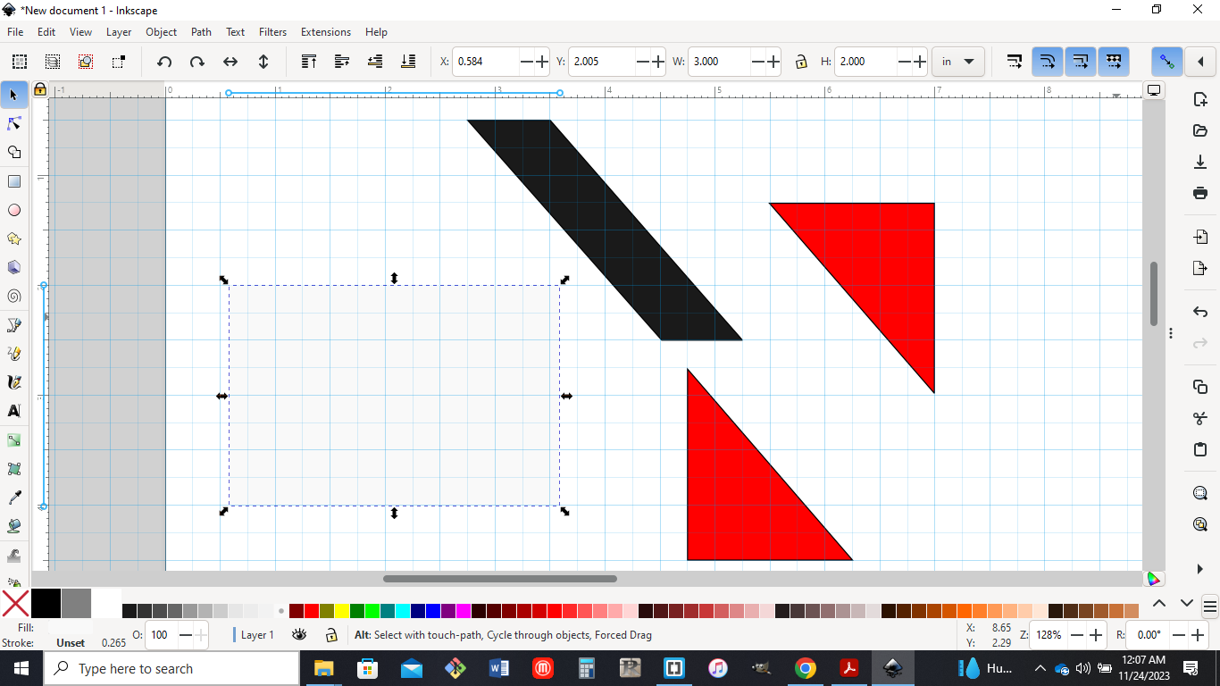
The rectangle tool was then selected on the left side tool palette and i drew a rectangle of size 3in x2 in and i selected the white fill colour.I made sure toggle snapping is on to the top right hand corner of the canvas.I then proceeded to draw 3 more shapes using the pen tool located on the left side toolbar.The two triangles fill colour was placed in red and the other shape in black.
Step4
I then used the selector tool on the left side toolbar to put the shapes in their desired position as shown below.
Step5
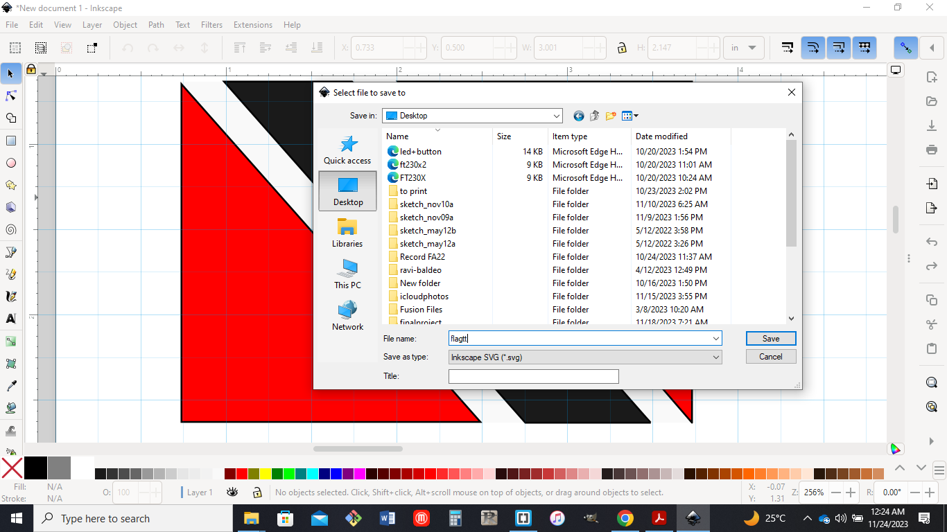
The file was then named and saved as an SVG file on the desktop.(file > save as > save)
I decided to use Fusion 360 for 3D Software
The first thing I did was download fusion 360 on my computer and signed into the software.
I was not familiar with fusion 360 so I did some practice with the software and also looked at some YouTube videos.
The following link is very useful if you dont have any experience with fusion360 and is a new user to the software.
https://academy.productdesignonline.com/collections/fusion-360-for-beginners
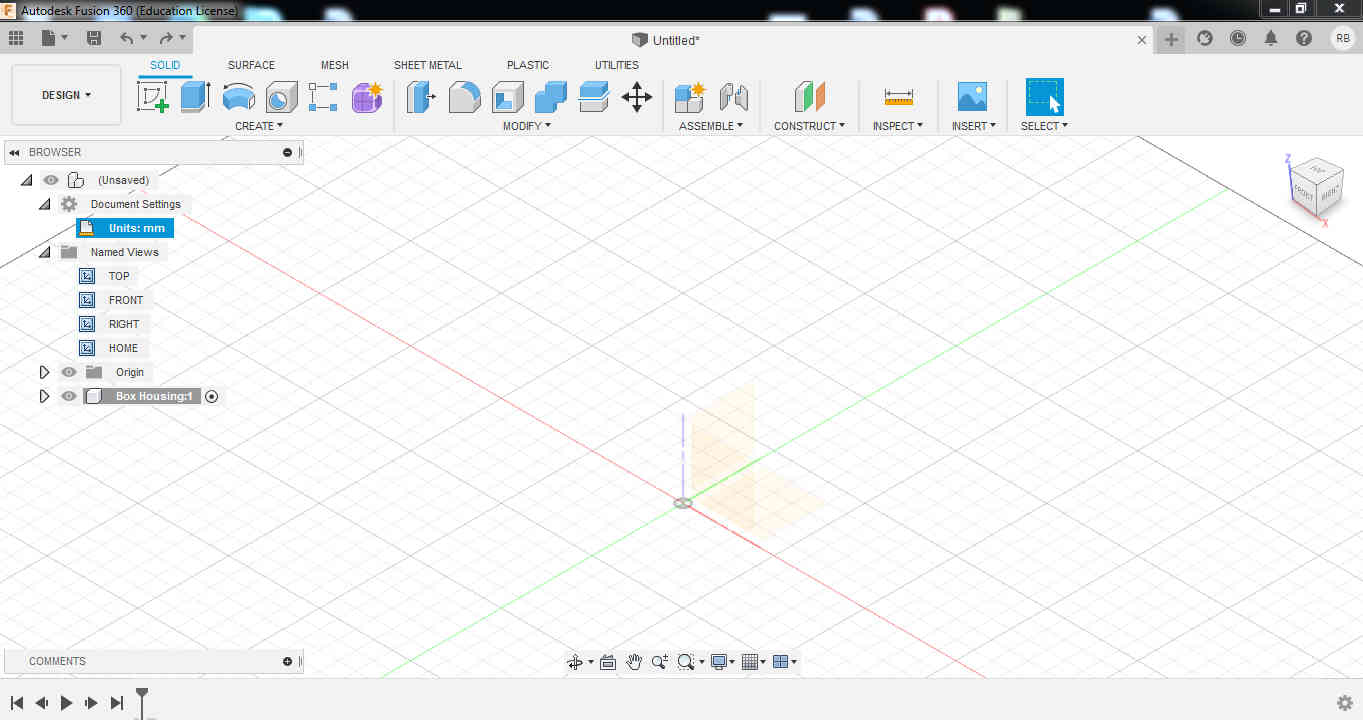
I did not have an idea what to draw at first but then i looked at my final project idea and decided to draw a box for the housing of my electronic componemts for the project .
I made sure that I was starting a new design and the units was in millimeters (mm).
The first thing I am going to do is to create a 2d sketch.
PROCEDURE
Step 1
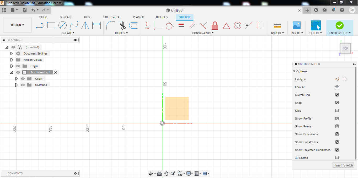
The first step I made was by drawing the outside perimeter of the box I selected a plane in the workspace and started to create my first sketch.
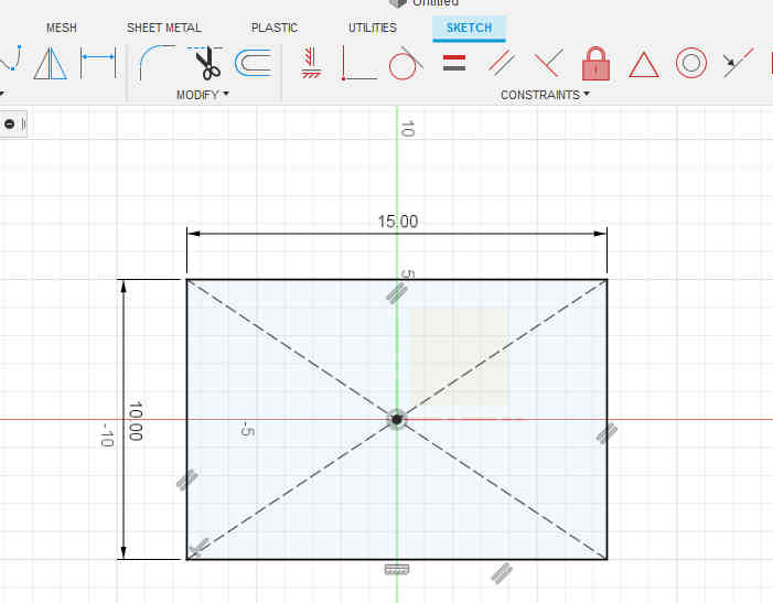
I used the center rectangle and using the arrow to the right I pinned it to the sketch menu. I then added dimensions to the box which will be 15cm in length and 10cm in width.
Step 2
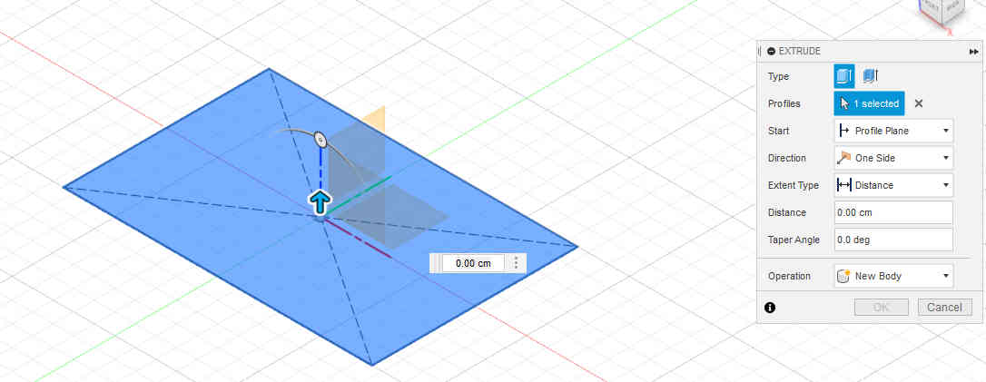
The next step will be extruding the 2d sketch I just made into the workspace.
This was done by clicking design then solid then modify then press pull, the press pull dialog then displays.
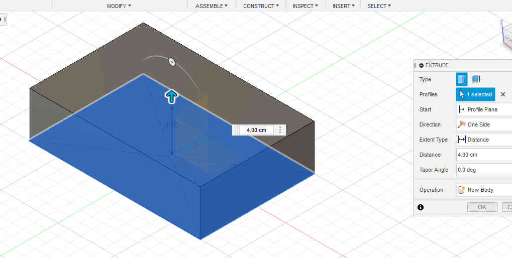
The manipulator handle was used to extrude the box to its desired height of 4cm.
Step 3
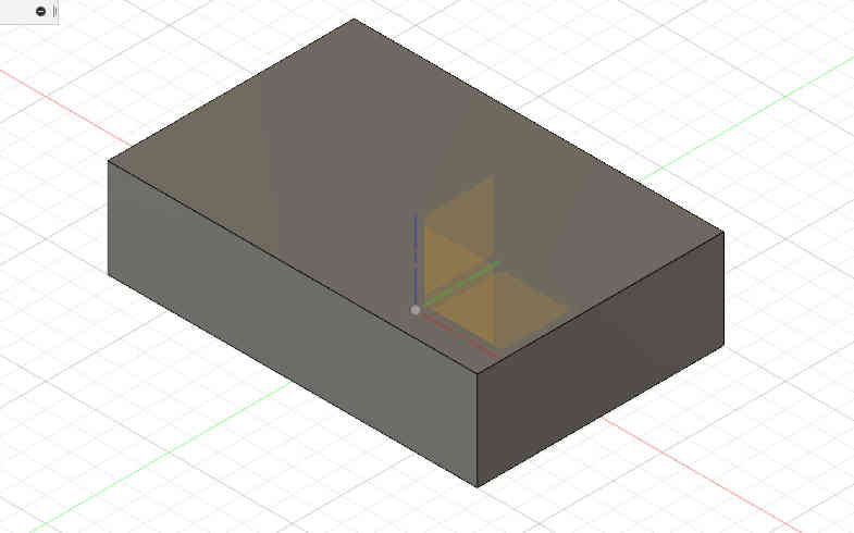
The next step will be to carve out the center portion of the solid I just created.
I am going to select the top face right click and create sketch again.
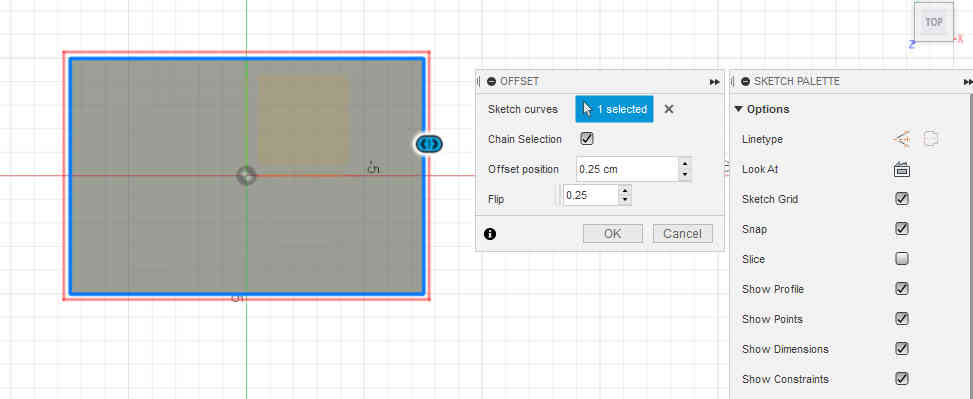
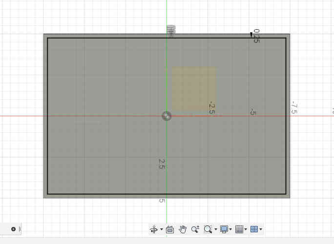
Now I am going to specify the thickness of the wall by offsetting the outer edges of the box.
Press the S key on the keyboard and then type offset in the search box, select the offset command as it comes up.
The thickness of the box was then selected to be -0.25cm.
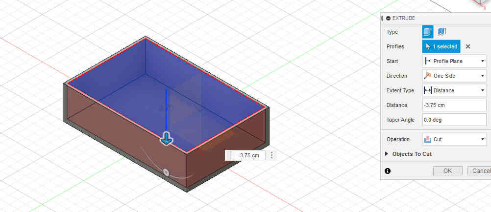
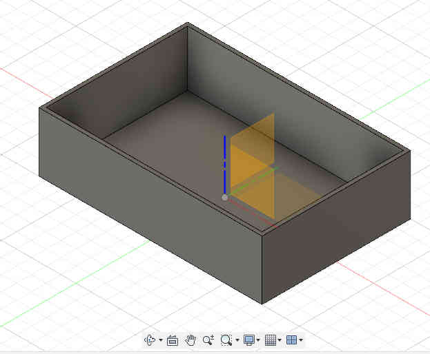
Step 4
The press pull command will be repeated for this step and in this case will be used to remove the inner potion of the solid hence the arrow will be moved in the opposite direction as did before.
Shortcuts used
S key on keyboard to get to the model toolbox.
Q key on the keyboard to get to the press pull command (note: the press pull is used to both extrude and subtract).
Conclusions
This week involved both using and testing new software related to 2D and 3D designing.I looked at different CAD Software such as AutoCAD,Gimp,Krita,Corel Draw and Fusion 360.Inkscape is very versatile and supports a wide variety of formats such as SVG, AI, EPS, PDF, and PNG.The software is very good for creating and editing vector graphics and also for creating logos and icons.The Fusion360 software is very versatile when come to generative design,simulation and additive manufacturing.Fusion360 is also capable of Parametric modelling,Mesh Modelling, Surface Modelling,CAD and CAM integration,Extremely realistic renders,Printed Circuit Board (PCB) layout, planning and manufacturing,Cooling of electronics and also Topology and shape optimisation.I decided to use inkscape for 2D design and Fusion360 for 3D designing.
Files
References
https://www.autodesk.com/solutions/cad-software