14. Interface and application Programming
Learning outcomes
- Implement a Graphical User Interface (GUI) using programming and explore protocols to communicate with an MCU board.
Objectives
- Link to the group assignment page.
- Document your process.
- Explained the GUI that you made and how you did it.
- Explain how your application communicates with your MCU board.
- Explain any problems you encountered and how you fixed them.
- Include original source code (or a screenshot of the app code if that’s not possible).
- Include a ‘hero shot’ of your application running & communicating with your board.
Link to the group assignment page
https://fabacademy.org/2021/labs/vancouver/students/christopher-proute/group/week16/
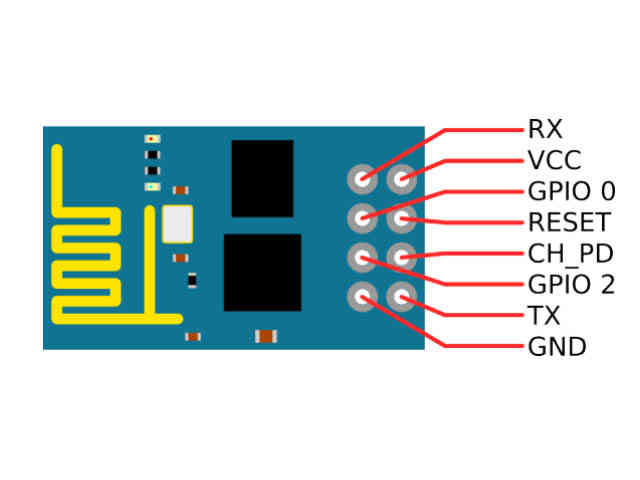
For this week assignment i decided to include the esp8266-01 wi-fi module.
I went to the website named remoteXY,the link is posted below.
https://remotexy.com/en/editor/code/
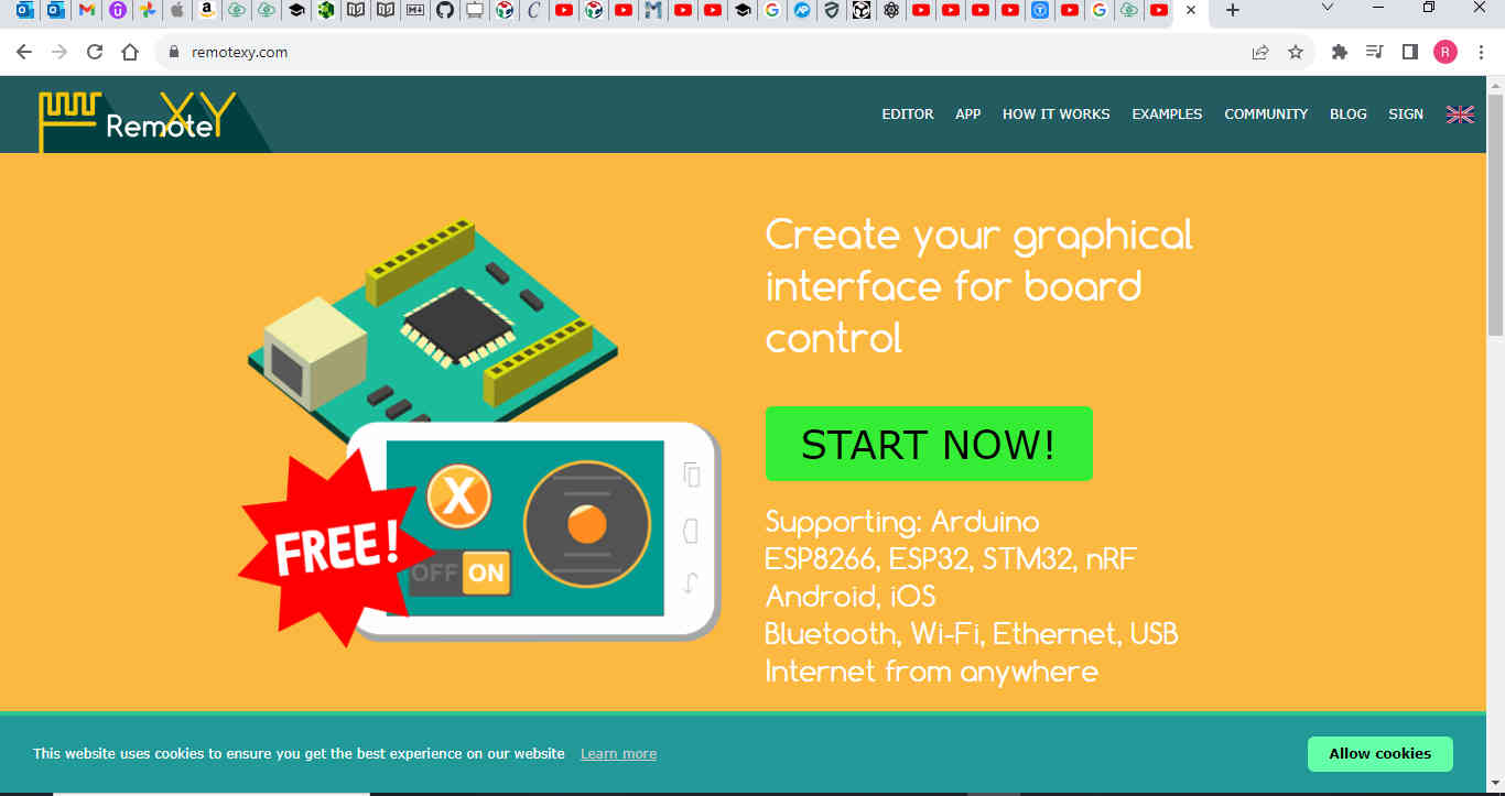
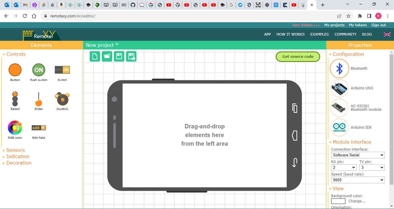
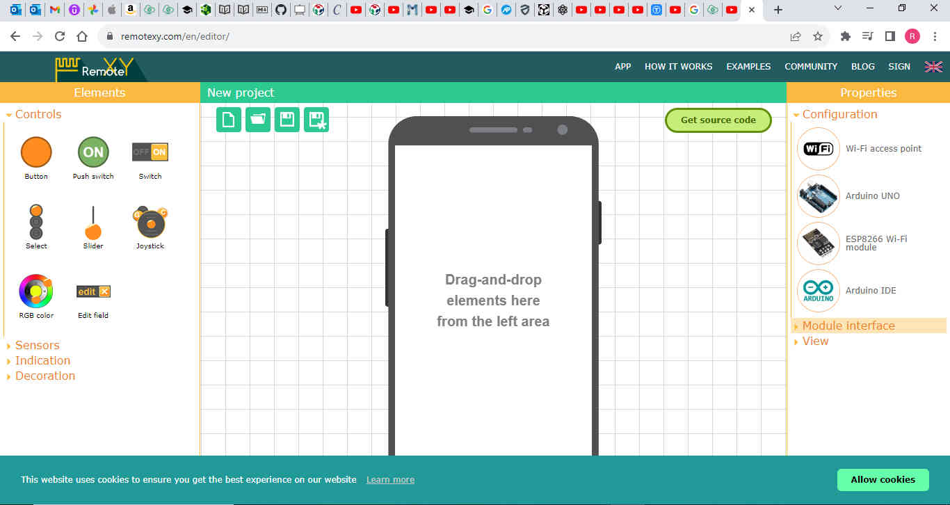
1)I clicked on editor in the top menu and it took me to a new project.

Properties
2)On the right panel i then proceeded to set the configuration menu by clicking on the bluetooth icon.
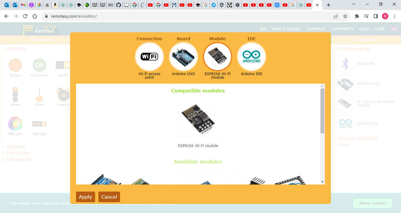
3)I made sure that the following was set:
Connection was set to Wi-Fi Board set to Arduino UNO Module set as ESP8266 Wi-Fi module IDE set to Arduino IDE
I then selected apply.
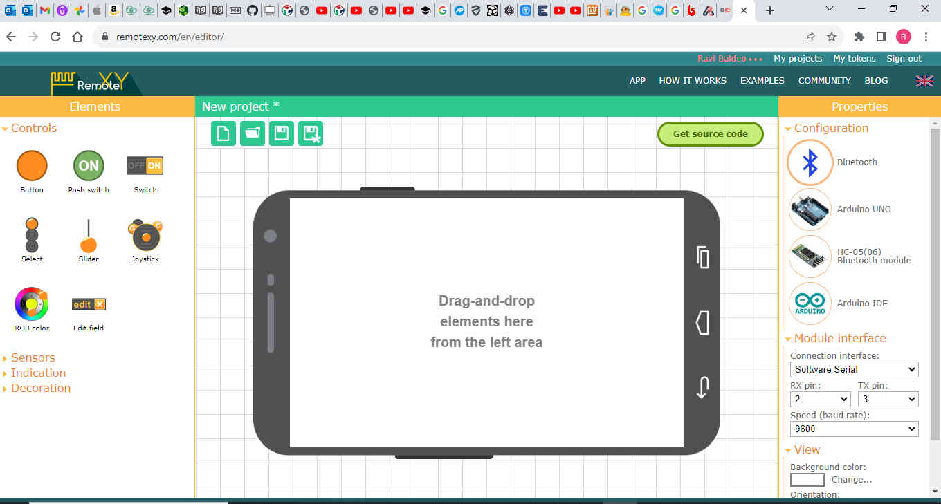
Module Interface
4)I then proceeded to set the module interface with the following settings listed below.
Connection interface set to hardware serial Baud Rare set to 115200 Serial,pin0(RX) and 1(TX) Wi-Wi access point as RemoteXY password set to 8 characters(12345678) port set to 6377
View
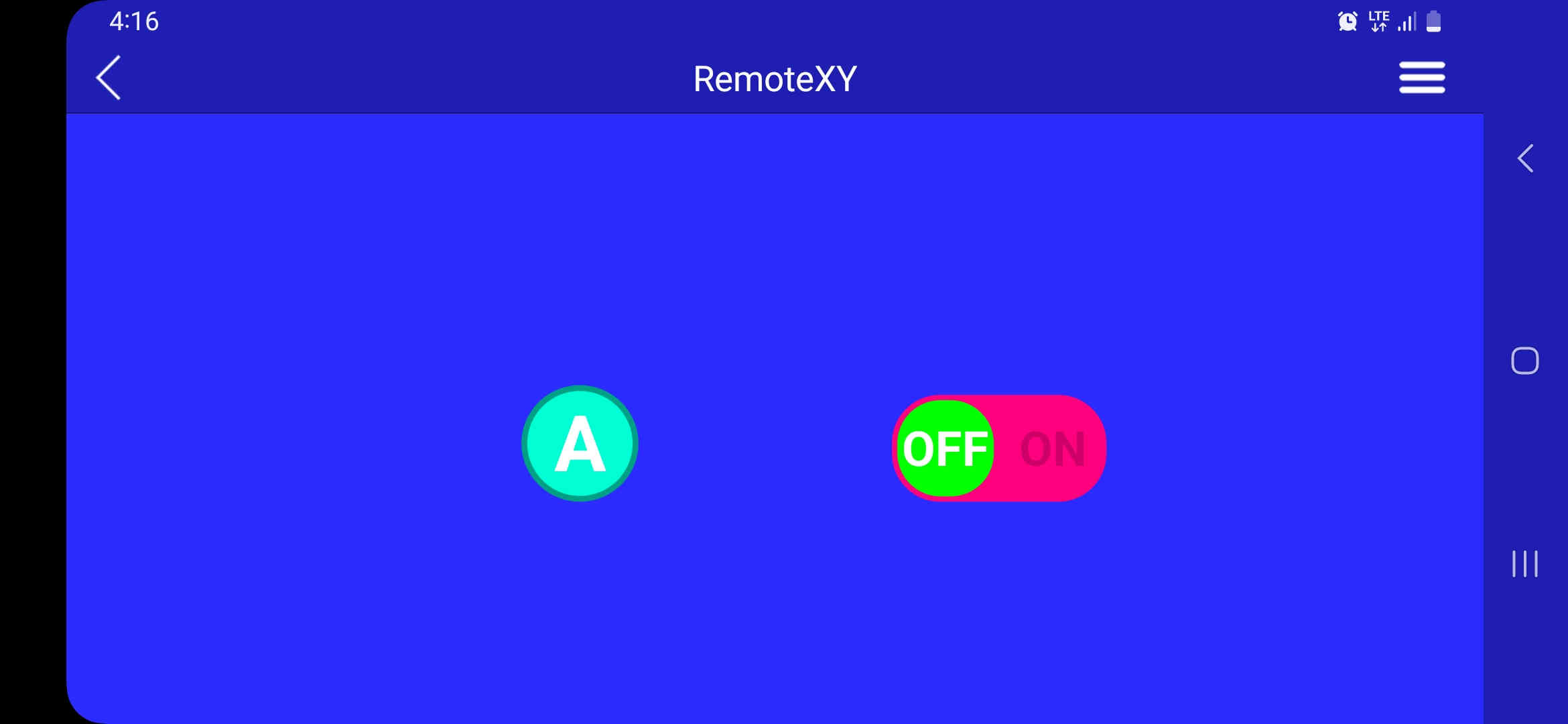
5)The background colour was set to blue and the orientation as horizontal

To the left side panel is where i dragged and dropped the controls onto the phone screen.This is the elements panel where i dragged a switch onto the screen.When i highlighted the switch some options came up under element where the conditions of the switch can be edited such as on and off state background colour and type..
One very important condition to note is which pin the switch is snapped to.
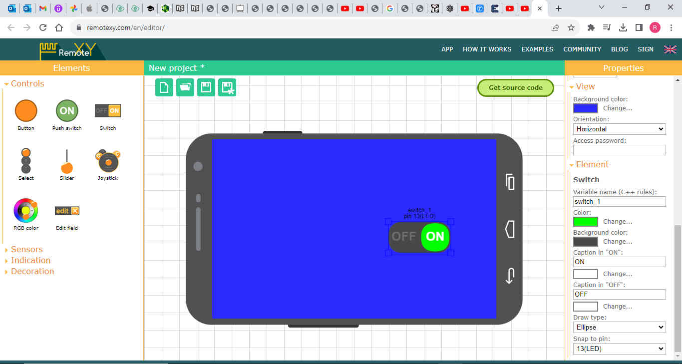
I then dragged a button onto the screen from the controls menu to the left. Another important point to note is to make sure and assign the button to the desired pin on my circuit.

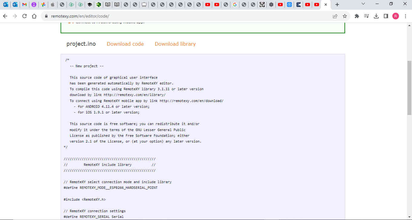
I then clicked on get source code and copied the code which i opeded using the arduino IDE.
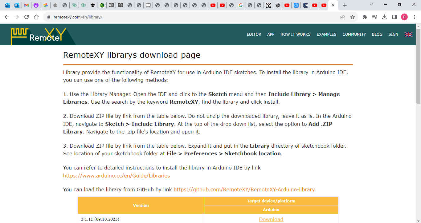
The remote XY library was downloaded from the following link on github.
https://github.com/RemoteXY/RemoteXY-Arduino-library

I saved and uploaded the code to my MCU board.
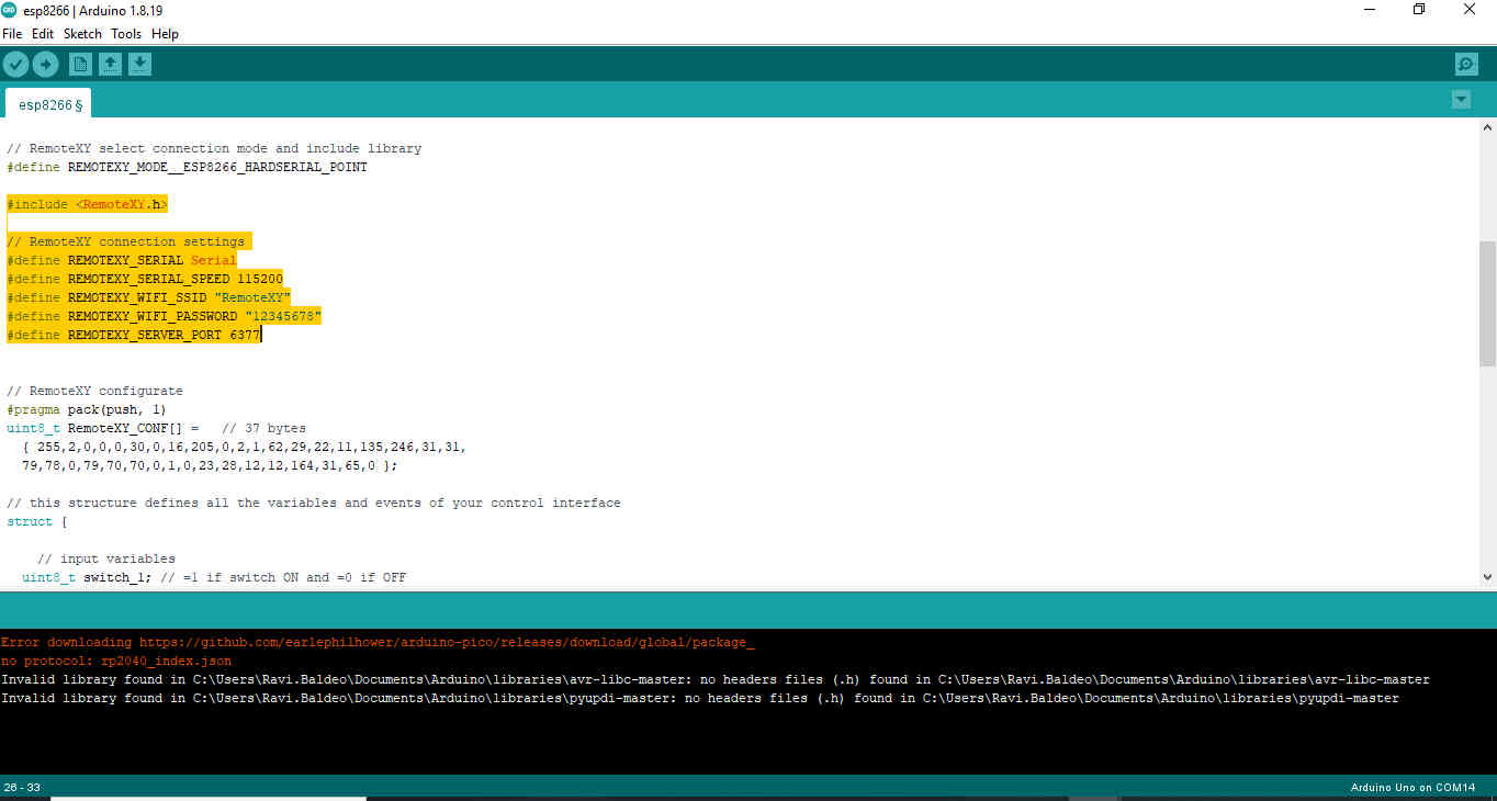


I removed the TX and RX pins while uploading the code.
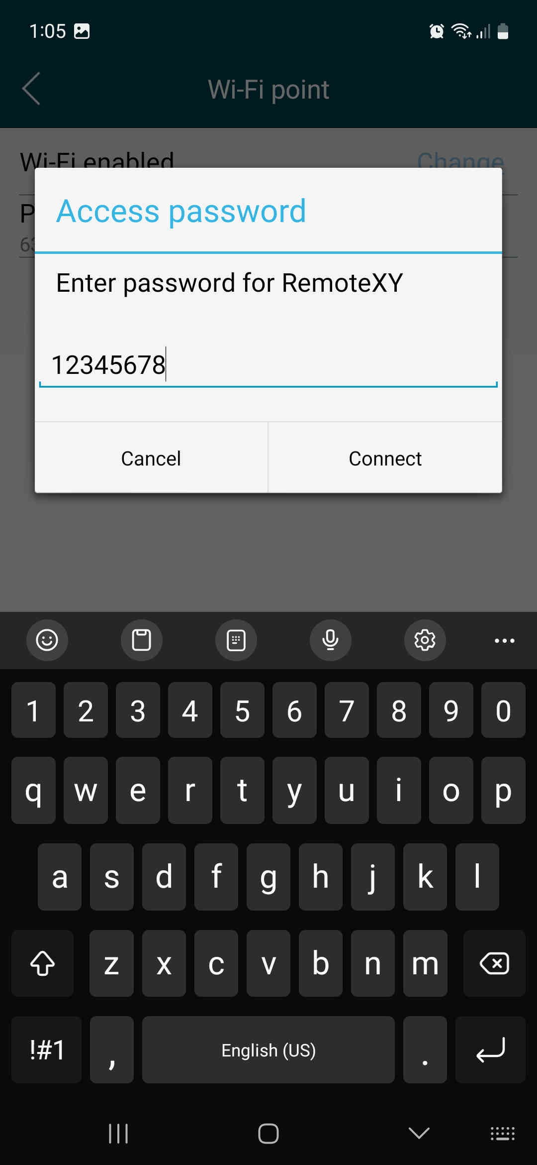
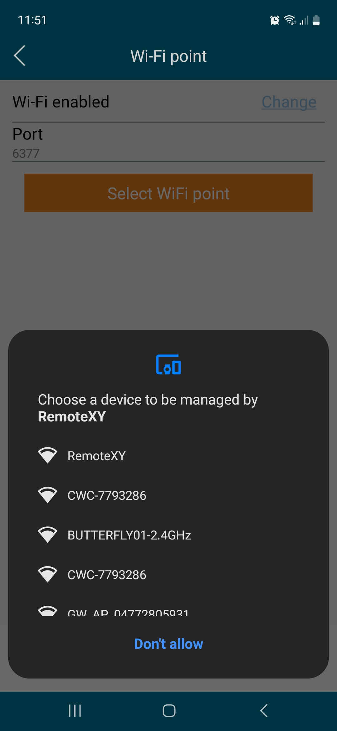
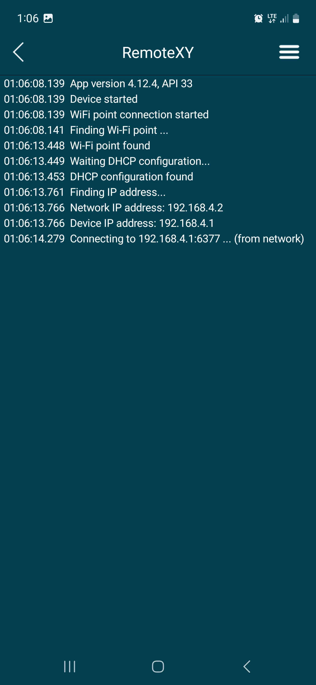
After connecting back the pins to my board i downloaded the remoteXY app and connected to the remoteXY wifi.
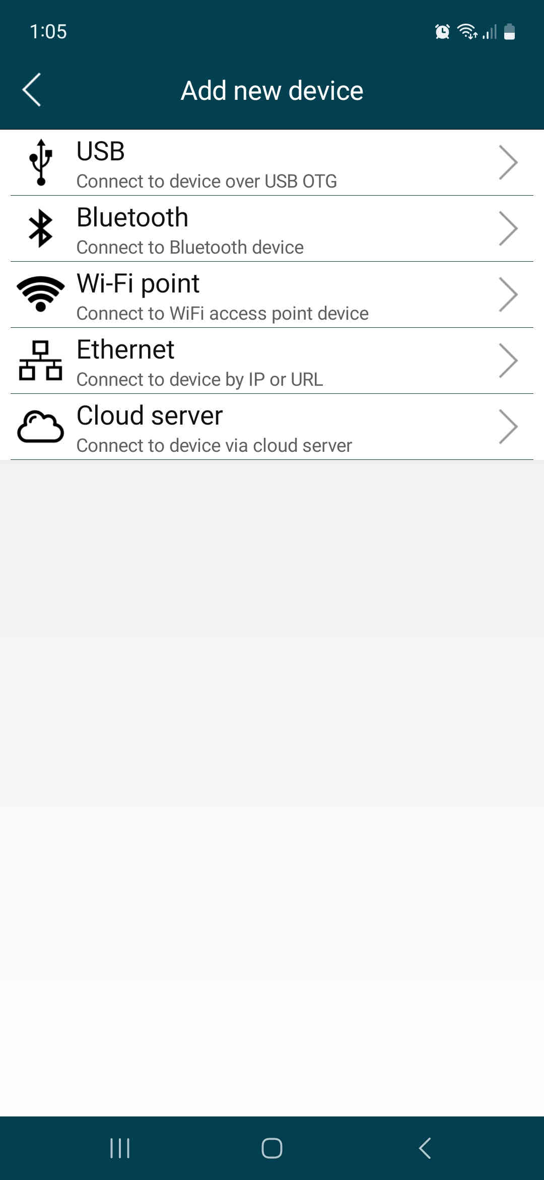
I had to add a device through the wi-fi access point being the esp8266-01 wi-fi module

The circuit connection was made as shown in the image below.
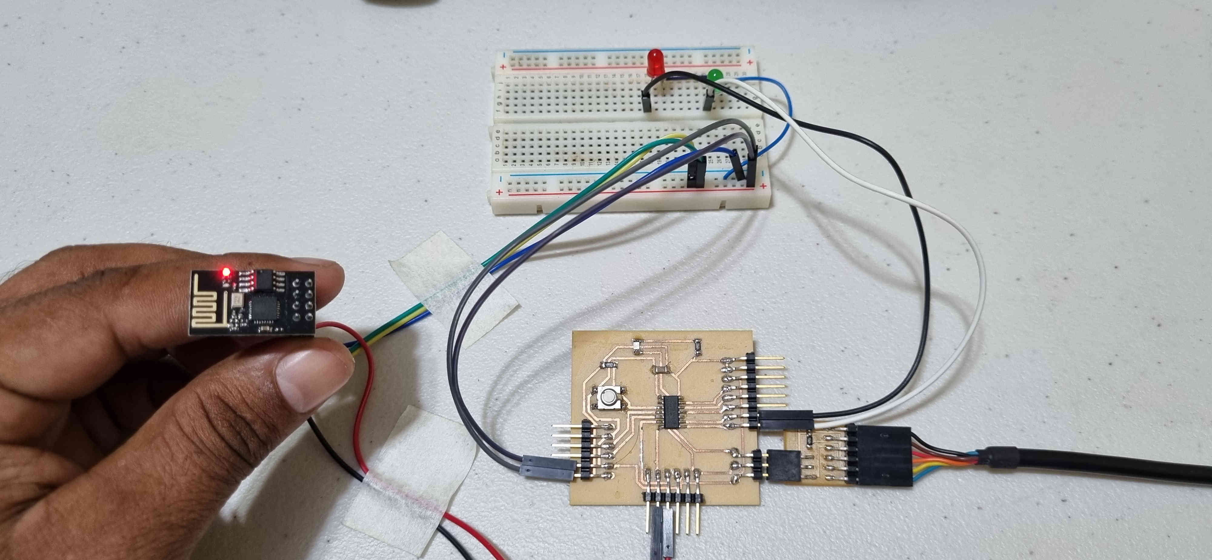
Connections Made to my mcu board and esp8266-01:
- TXD > pin7
- RXD > pin6
- switch pin > pin8
- button pin > pin9
Code generated from remoteXY editor
/*
   -- New project --

   This source code of graphical user interface
   has been generated automatically by RemoteXY editor.
   To compile this code using RemoteXY library 3.1.11 or later version
   download by link http://remotexy.com/en/library/
   To connect using RemoteXY mobile app by link http://remotexy.com/en/download/
     - for ANDROID 4.11.4 or later version;
     - for iOS 1.9.1 or later version;

   This source code is free software; you can redistribute it and/or
   modify it under the terms of the GNU Lesser General Public
   License as published by the Free Software Foundation; either
   version 2.1 of the License, or (at your option) any later version.
*/

//////////////////////////////////////////////
//        RemoteXY include library          //
//////////////////////////////////////////////

// RemoteXY select connection mode and include library
#define REMOTEXY_MODE__ESP8266_HARDSERIAL_POINT

#include <RemoteXY.h>

// RemoteXY connection settings
#define REMOTEXY_SERIAL Serial
#define REMOTEXY_SERIAL_SPEED 115200
#define REMOTEXY_WIFI_SSID "RemoteXY"
#define REMOTEXY_WIFI_PASSWORD "12345678"
#define REMOTEXY_SERVER_PORT 6377


// RemoteXY configurate
#pragma pack(push, 1)
uint8_t RemoteXY_CONF[] =   // 36 bytes
  { 255,2,0,0,0,29,0,16,205,0,2,0,64,27,22,11,2,26,31,31,
  79,78,0,79,70,70,0,1,0,20,28,12,12,2,31,0 };

// this structure defines all the variables and events of your control interface
struct {

    // input variables
  uint8_t switch_1; // =1 if switch ON and =0 if OFF
  uint8_t button_1; // =1 if button pressed, else =0

    // other variable
  uint8_t connect_flag;  // =1 if wire connected, else =0

} RemoteXY;
#pragma pack(pop)

/////////////////////////////////////////////
//           END RemoteXY include          //
/////////////////////////////////////////////

#define PIN_SWITCH_1 6
#define PIN_BUTTON_1 7


void setup()
{
  RemoteXY_Init ();

  pinMode (PIN_SWITCH_1, OUTPUT);
  pinMode (PIN_BUTTON_1, OUTPUT);

  // TODO you setup code

}

void loop()
{
  RemoteXY_Handler ();

  digitalWrite(PIN_SWITCH_1, (RemoteXY.switch_1==0)?LOW:HIGH);
  digitalWrite(PIN_BUTTON_1, (RemoteXY.button_1==0)?LOW:HIGH);

  // TODO you loop code
  // use the RemoteXY structure for data transfer
  // do not call delay(), use instead RemoteXY_delay()


}
Circuit Testing
Original Design files and source code
References
https://remotexy.com/en/editor/
https://www.youtube.com/watch?v=2cjufbgOBYo&t=61s
https://www.youtube.com/watch?v=2cjufbgOBYo&t=61s