3. Computer controlled cutting
Learning outcomes
- Demonstrate and describe parametric 2D modelling processes.
- Identify and explain processes involved in using the laser cutter.
- Develop, evaluate and construct a parametric construction kit.
- Identify and explain processes involved in using the vinyl cutter.
Objectives
- Link to the group assignment page.
- Explain how you created your parametric design.
- Document how you made your press-fit kit.
- Document how you made something with the vinyl cutter.
- Include your original design files.
- Include hero shots of your results.
Link to the group assignment page
https://fabacademy.org/2021/labs/vancouver/students/terrence-carew/assignments/week03g.html
Using the Vinyl Cutter
The machine present at our lab is the Roland camm-1 gs-24 as shown below.

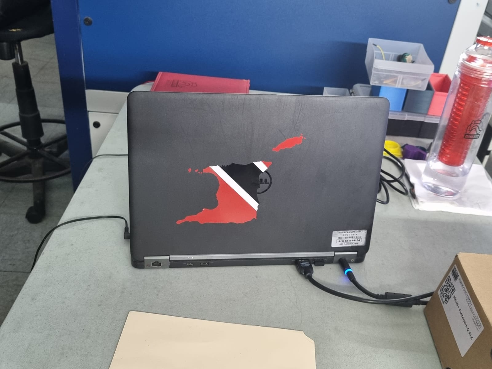
The first thing i did for this week assignment was created a vinyl sticker.I cut a sticker using a combination of red black and white vinyl.
The image used was downloaded from the following website: - Trinidad and Tobago
Open Roland cut studio and import the image (jpeg format) Go to file cutting set up and set the appropriate units to work with(inches)

The file was converted into a vector file following the steps below before it is ready for cutting with the vinyl cutter:
- Right click on the image and select image outline

- Select extract contour lines and click ok
- Drag the outline and delete the original image
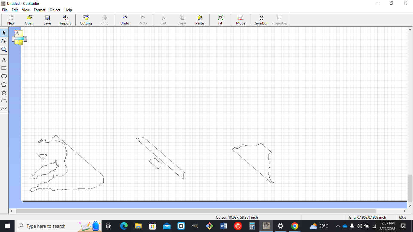
The traces in the above image were cut as follows:
- ones to the left were cut in red
- the center 2 pieces were cut in white vinyl
- the piece to the right was cut in black
using the machine
I went to the back of the machine and loaded the roll under the pinch rollers. Using the lever on the top left hand corner I lock the roll into place, making sure pinch rollers are positioned under the white strips on the machine (near the ends of the material)
The following steps was then executed for cutting of the vinyl:
- Connect and boot up the machine
- Select roll
- Hit enter on the machine and the machine will measure the diatance between the pinch rollers
- Jog the material so that the material will be set in place for cutting
- Then hold the origin button to set the start point for cutting of the material.
A test was done to make sure the force and blade depth is set correctly so that it does not cut through the back of the material.
I pressed the menu button to check the force offset and speed settings on the machine
Cutting Settings and software Used
size of image that was cut - 5”(width) x 4”(length)
cutting area - 23.00”(width) x 62.99”(length)
pen force - adjusted from the zero position to +0.5
cutting speed - 19.69 in/s(10-50 mm/s)
software - roland cutstudio
Designing a lampshade using fusion 360
TOP CIRCLE
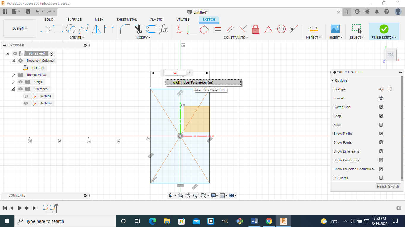
I decided to use Fusion360 this week for my design so i started to design a new component which I called the top circle. I then changed the document unit settings to Centimeters.
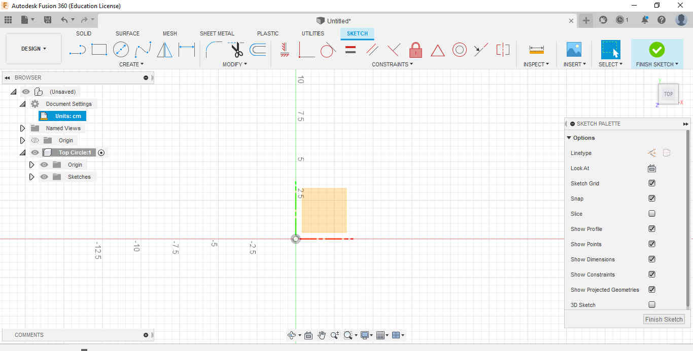
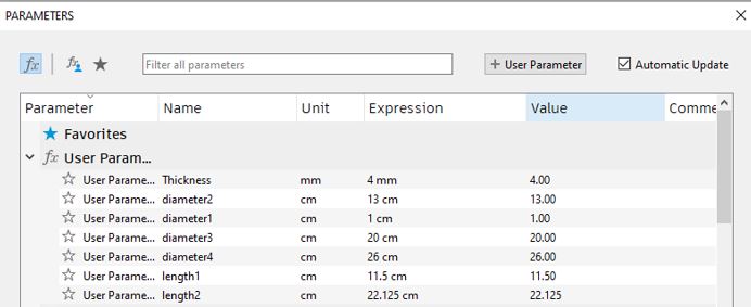
I started by assigning the parameters that i think needed to be used such as length,thickness and diameter.
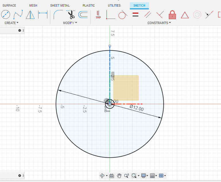
The next step was to start creating a sketch. I selected the center circle diameter in the sketch panel and drew a circle of diameter 12cm. Then I right clicked at the center of the circle and repeat the center circle diameter with a smaller circle of 1cm.
Select line from the sketch menu and create a line sketch from the center of the circle to the top at a distance of 6.5cm. Click on the sketched line to highlight it and change the line to a construction line from the drop down menu at the right. Go to create and select rectangle and in the dropdown select center rectangle. Create a center point rectangle at the circumference of the circle and make it 0.35cm x 1.1cm.

Select the rectangle go to create and in the drop down menu select rectangular pattern.
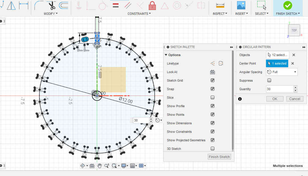
Select the rectangle go to create and in the drop down menu select circular pattern. Specify the center point of the circle and the quantity of the selected object you want around the circumference of the circle from the drop down menu to the right.
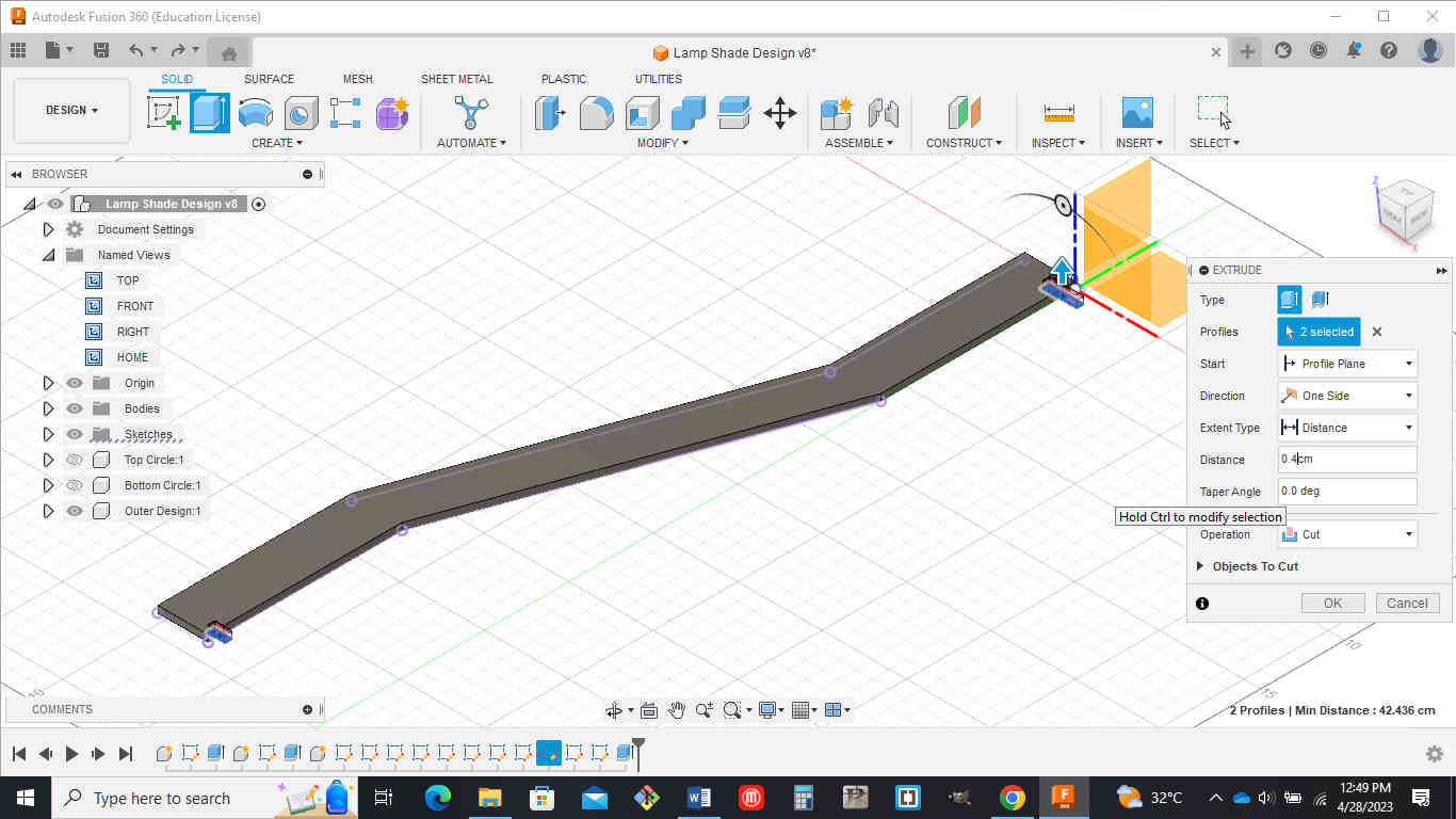
After doing this go back to the solid menu and select the extrude command. Select the object to be extruded and enter the desired value(0.393cm)
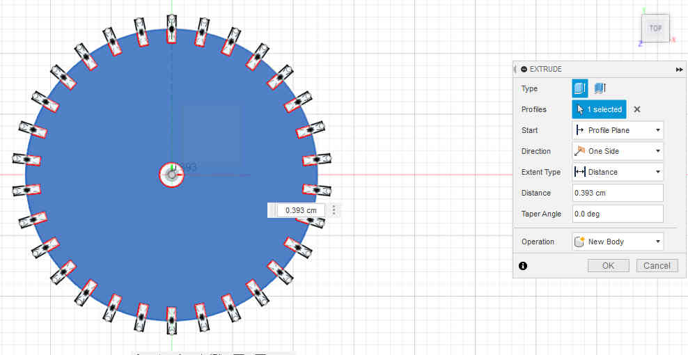
After doing this go back to the solid menu and select the extrude command. Select the object to be extruded and enter the desired value(0.393cm)

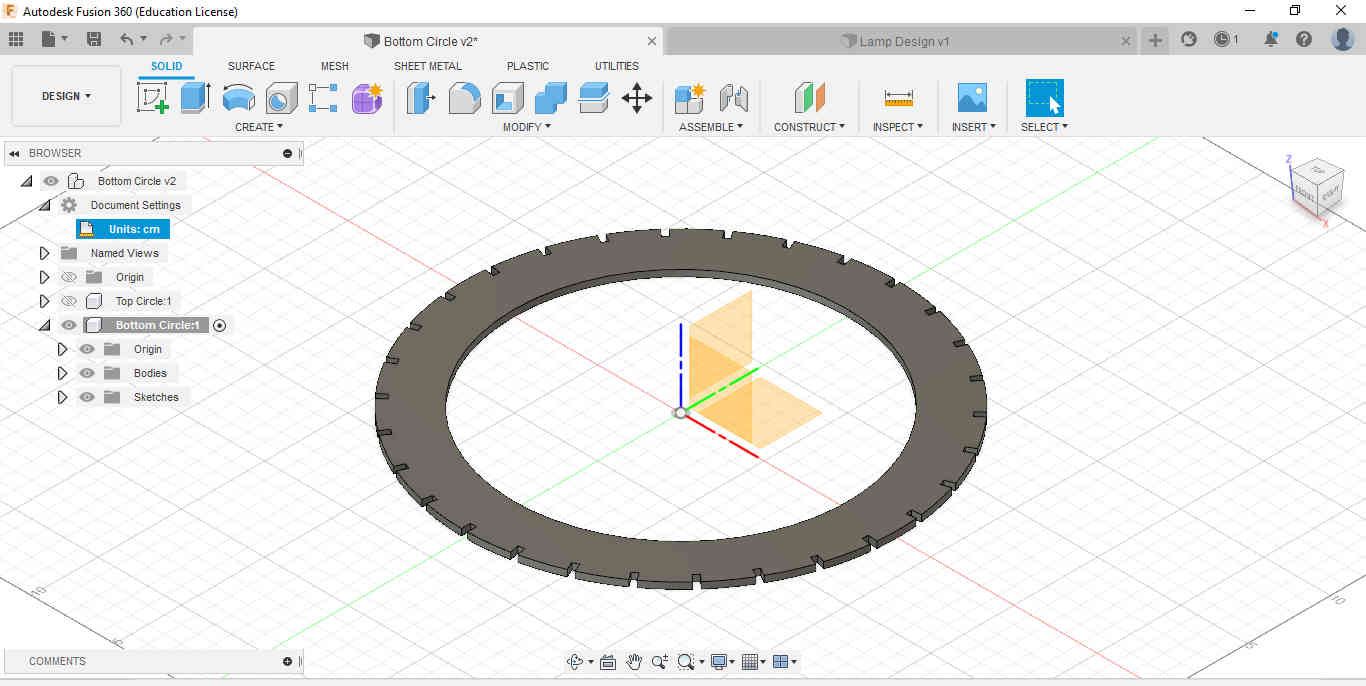
BOTTOM CIRCLE
I created a new component which will be called bottom circle.Then create a sketch and draw a circle of center diameter to be 26cm.
Now create a second circle using the same CenterPoint od diameter 20cm.

Repeat construction line step (see top)
This step will be used to extrude the bottom circle at the same thickness of the top circle.
OUTER DESIGN
Create a new component and name it outer design. We will start by creating a sketch and drawing a line 3cm long horizontally. Next draw a vertical line touching the left end of the horizontal line previously drawn. (11.5cm long)

The three bodies created were put together using the move and align tool that can be found under modify and assemble
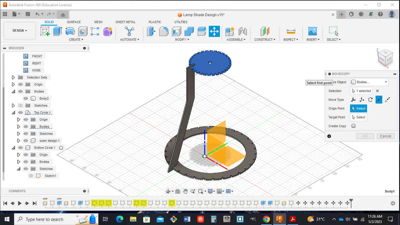
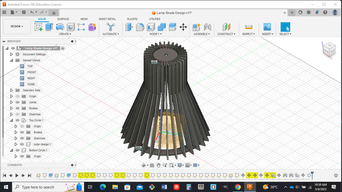
A circular pattern was then created from the create menu to add the patten around the lampshade.

The file was exported accounting for the kerf Kerf = 0.008inches which is 0.2032mm
Go to utilities then add ins and on the drop down menu,navigate to the fusion 360 app store Search for dxf laser and download the windows version
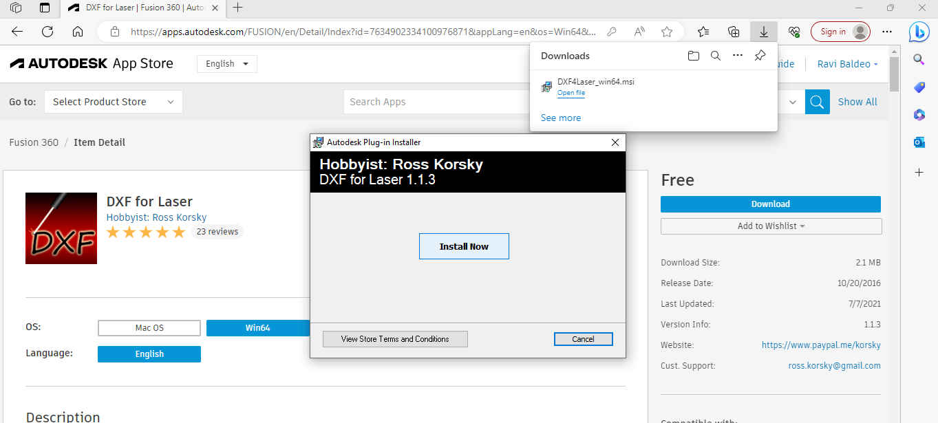
Now i went to the create tab and in the dropdown i selected save DXF for laser cutting.
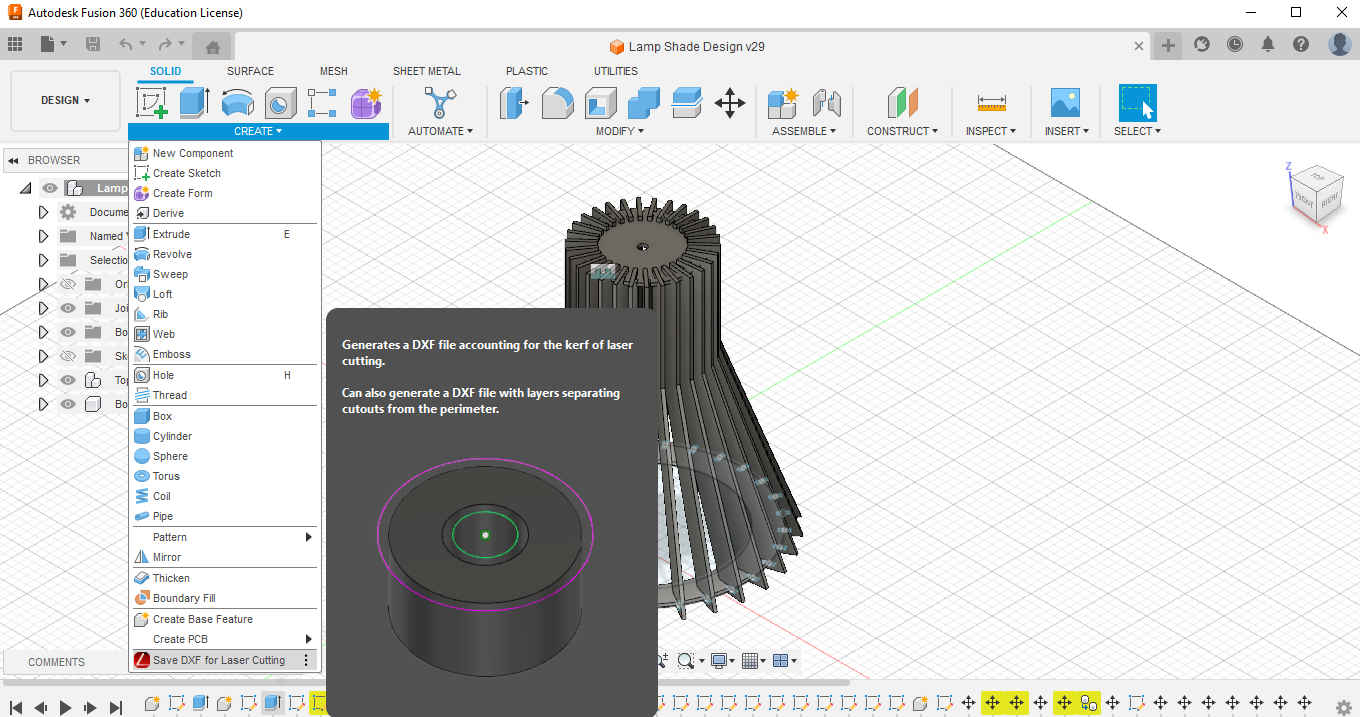
Note: Fusion 360 have to be closed and reopened to see the plug in take effect Select the face you want to cut and input the kerf after which the file will be saved as a dxf(repeat this step for each individual face)

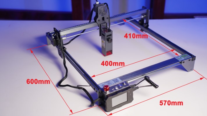
The machine used for the laser cutting was the atomstack x7 pro.The dimensions of the machine are shown below.
The software used for the laser cutting was lightburn and the settings used is shown in the image below.
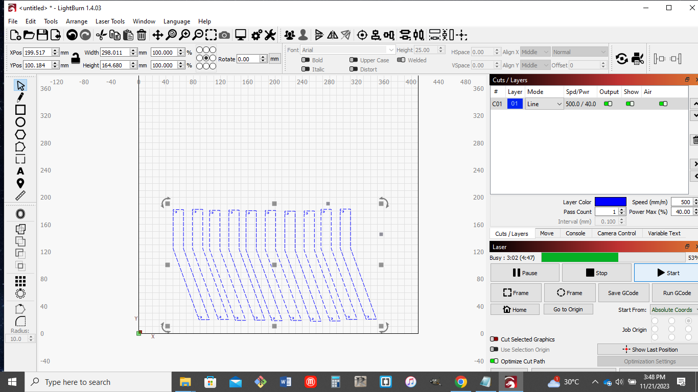
The cut settings used from the lightburn software are as follows:
- speed(mm/m) - 500
- power max (%) - 50.0
- pass count - 1
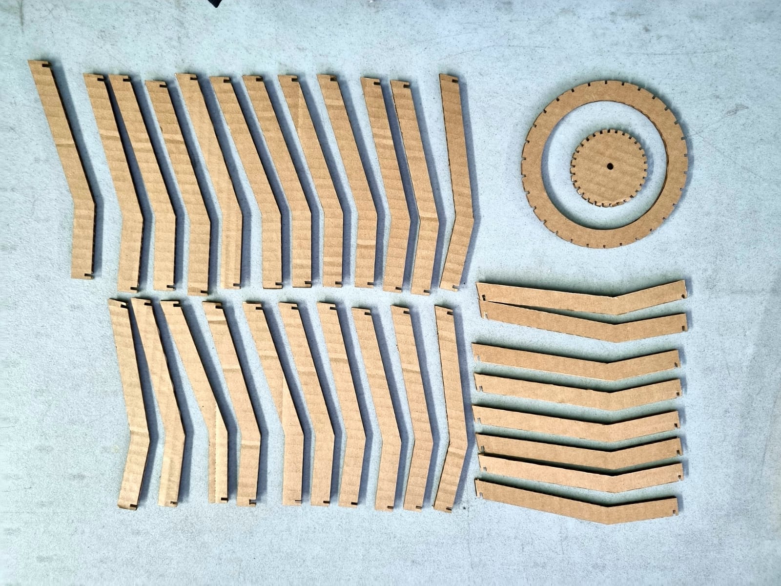
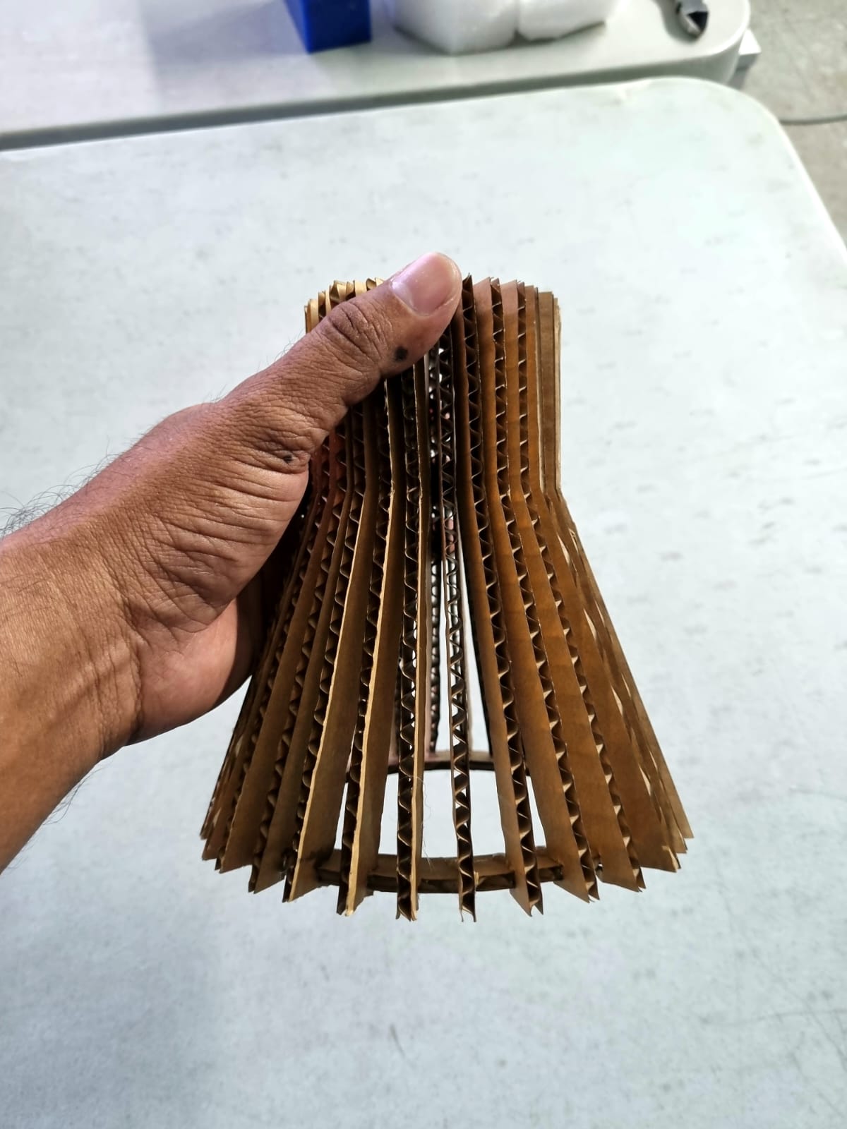
The image below shows the laser cut parts in cardboard.
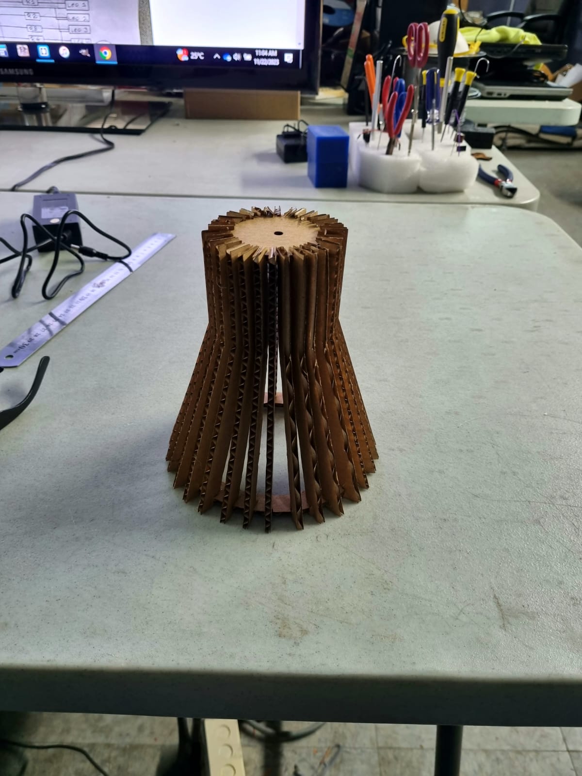
Hero Shots