4. Electronics Production
Learning outcomes
- Described the process of tool-path generation, milling, stuffing, de-bugging and programming
- Demonstrate correct workflows and identify areas for improvement if required
Objectives
- Linked to the group assignment page
- Documented how you made (mill, stuff, solder) the board
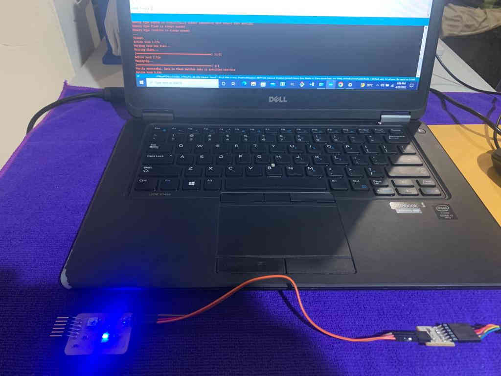
- Documented that your board is functional
- Explained any problems and how you fixed them
- Uploaded your source code
- Included a ‘hero shot’ of your board
Link to the group assignment page
https://fabacademy.org/2021/labs/vancouver/students/christopher-proute/group/week05/
This week I worked on the following :
Carbide motion is the controlling software for the machine and was downloaded from the following link posted below. https://carbide3d.com/carbidemotion/
Carbide create is the Computer aided Manufacturing Software (CAM) that the machine uses to convert the file in order to read it. The software was downloaded from the following link posted below. https://carbide3d.com/carbidecreate/
A printed circuit board(PCB) is basically the backbone of all electronic devices that exist today. It consists of a printed conducting copper circuit on a non-conductive board, components are connected over the traces.
In order for the file i created in electronics design week to be used in carbide create it needed to be in an SVG format.
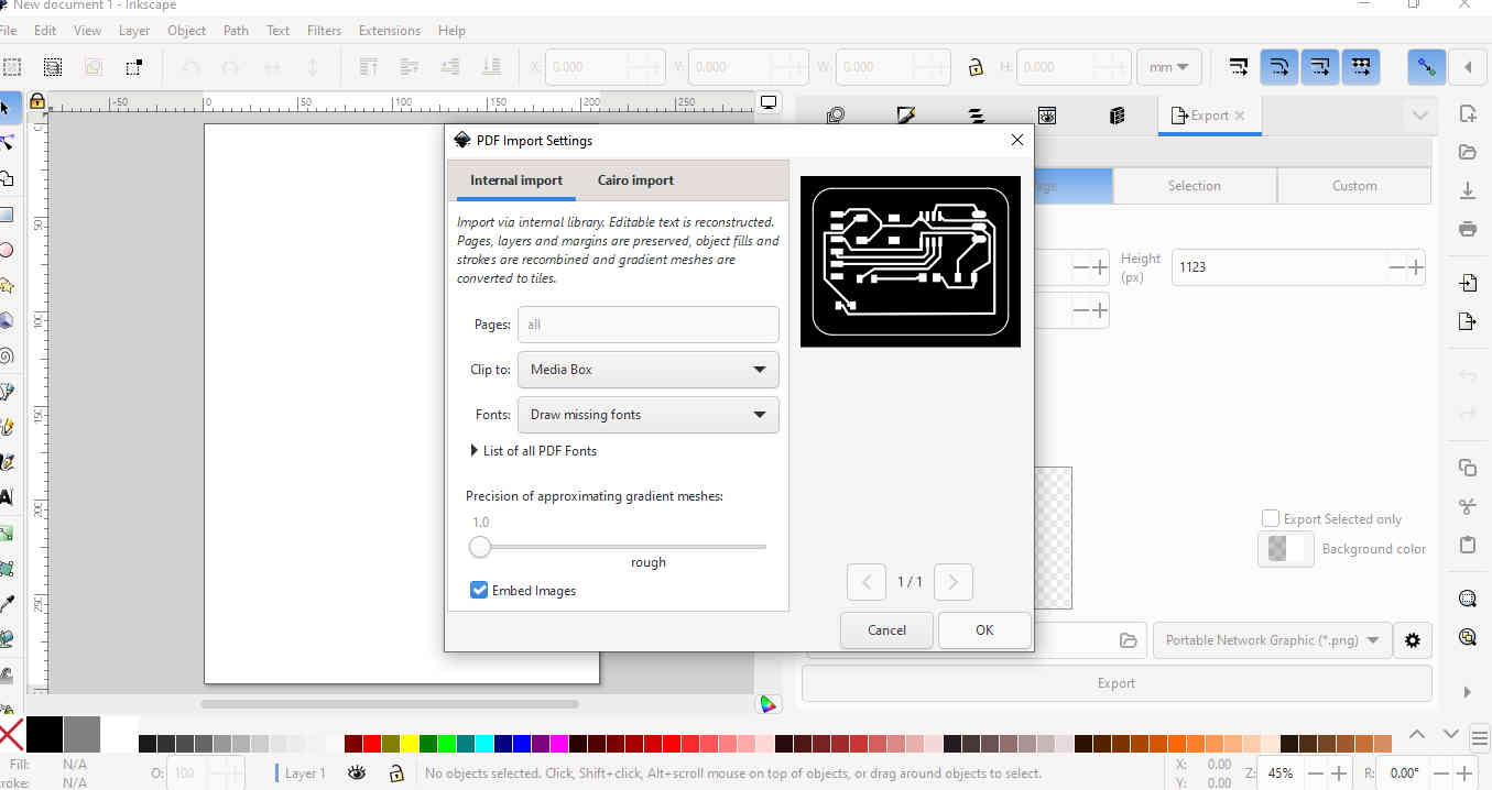
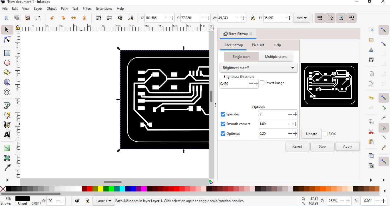
I used inkscape to create the correct file format by importing it > trace bitmap and > exporting it as SVG.
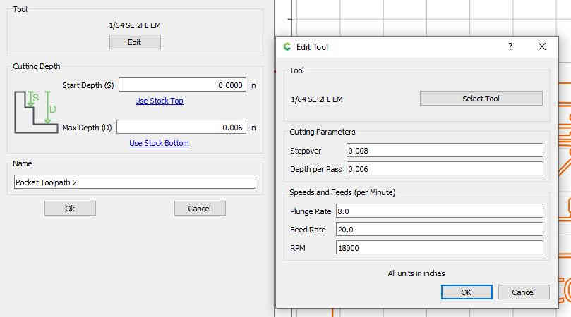
I located the SVG file on my computer and opened it in carbide create.

The next two images show the settings and the relevant toolpaths generated in carbide create

The image below shows the bits used for the milling process.
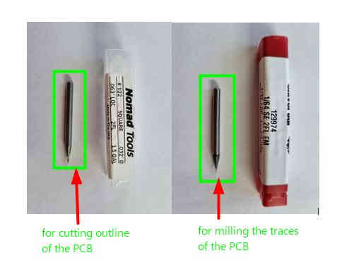
The material was secured to the base plate by using double sided tape.
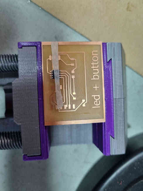
Milling of the PCB.

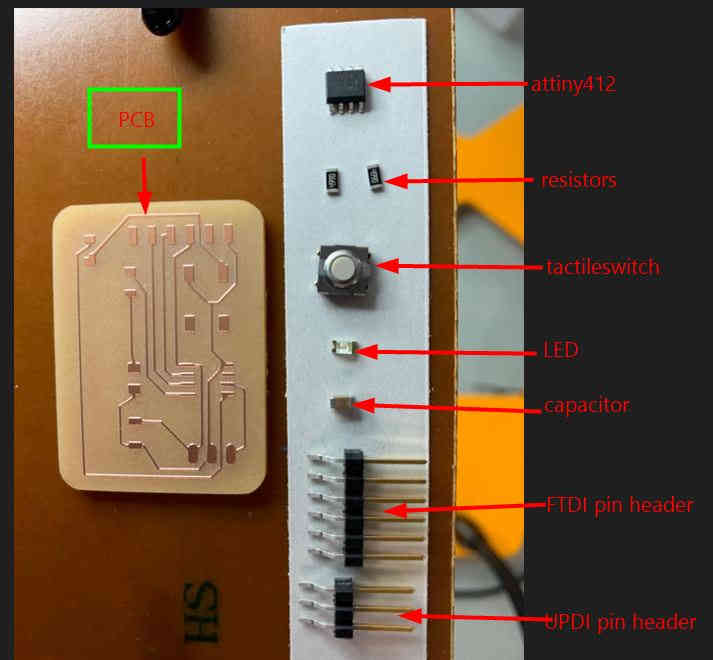
Stuffing the PCB.
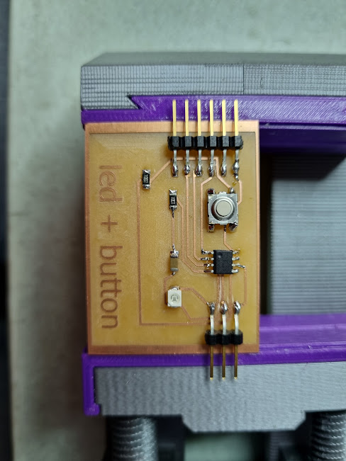
Hero Shot
Programming the PCB
I used the basic blink code from the arduino software and changed the pin number to match my design:
I opened the arduino software and went to file > examples > basic > blink.
Blink Code
int ledPin =2;
void setup() {
   pinMode(ledPin, OUTPUT);
}
void loop() {
  digitalWrite(ledPin, HIGH);
  delay(1000);
  digitalWrite(ledPin, LOW);
  delay(1000);
}
Video
References
https://www.circuitgeeks.com/arduino-led-blinking/
Process of Sending to a Board House
- Firstly, you need to design a circuit in any electronics design software. (e.g. Ki Cad or Fusion360)
- The next step would be to mill the circuit board using a milling machine and to test the circuit board in a laboratory or fablab to ensure that the circuit board is working as with the intended design.
- Then you would have to locate a PCB house on the internet such as jlcpcb.
- After this you would need to send the Gerber file of the design in a zip format. (with respect to PCB strength or rigidity you would need to explore factors such as solder mask, thickness, Colour etc.)
- After the size of the PCB is set you can proceed to make the necessary payment required. (be sure to set address, delivery method etc.)