8. Electronics design
Learning outcomes
- Select and use software for circuit board design.
- Demonstrate workflows used in circuit board design.
Objectives
- Link to the group assignment page.
- Document what you have learned in electronics design.
- Explain problems and how you fixed them.
- Include original design files (Eagle, KiCad, etc.).
- Include a ‘hero shot’.
https://fabacademy.org/2021/labs/vancouver/students/terrence-carew/assignments/week06g.html
I used the EasyEDA software to design my schematic for my hello world board.
I downloaded EasyEDA from the following link and created an account.
https://easyeda.com/page/download
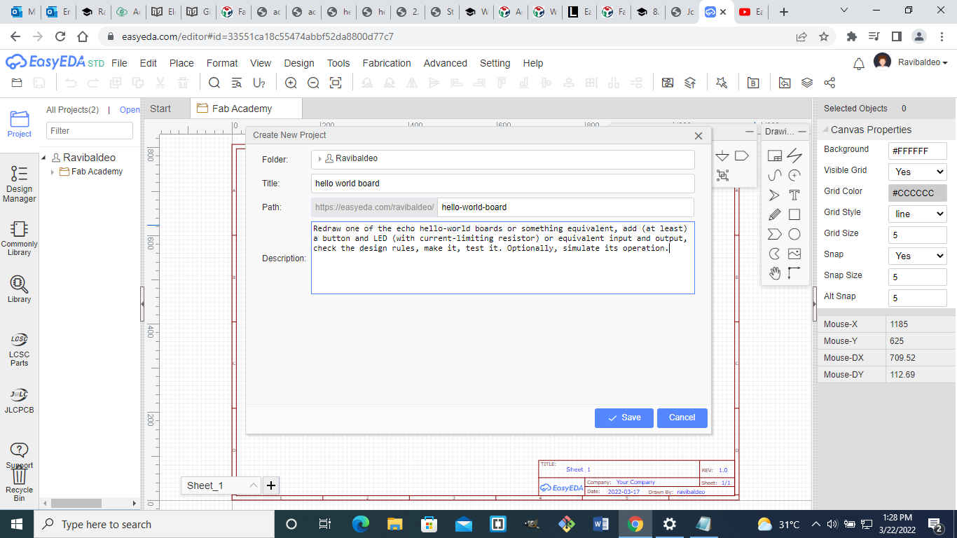
I clicked on the file button next to the easyeda logo at the top left hand corner to create a new project.A small window opened up where i can type the project name and also has an option to give a brief description of the project.I called the project hello world board.
The fab library was downloaded via the following link:
https://gitlab.fabcloud.org/pub/libraries/electronics
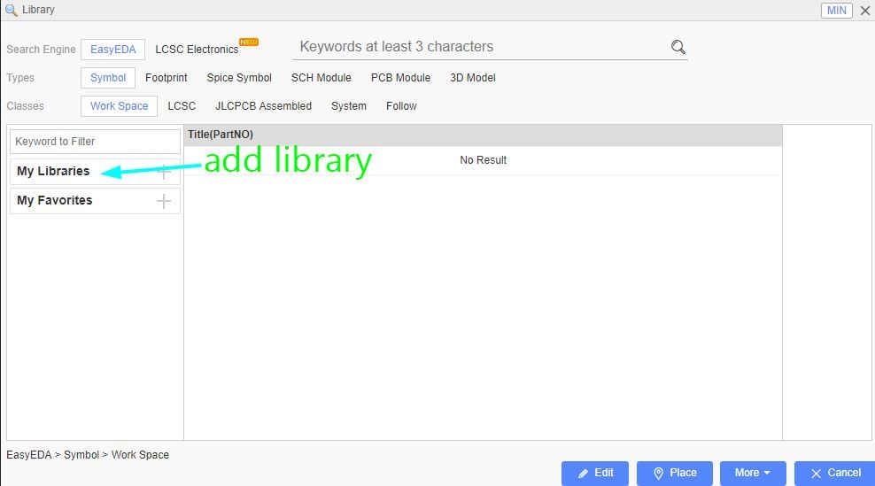
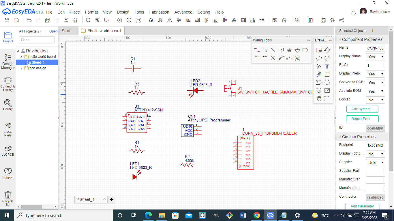
After adding the fab library I selected the components I needed and placed them on the workspace as shown in the image below.
Note EasyEDA has an online library and sharing components is very useful as if a user creates a new component it will appear in the online library
The following components was used for the design of the schematic diagram:
- 2 Resistors(1k)
- Capacitor(1uf)
- LED
- attiny 412
- UPDI connector
- FTDI connector
- tactile switch
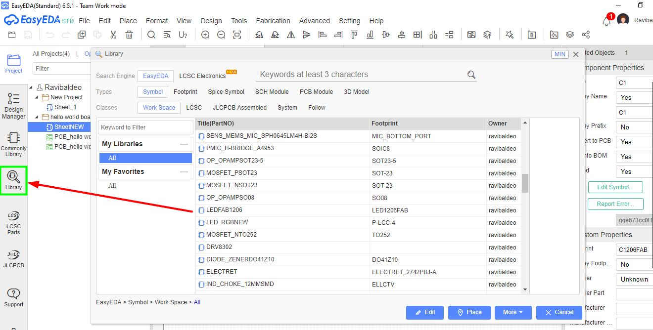
The components was added from the library tab located on the left side panel.
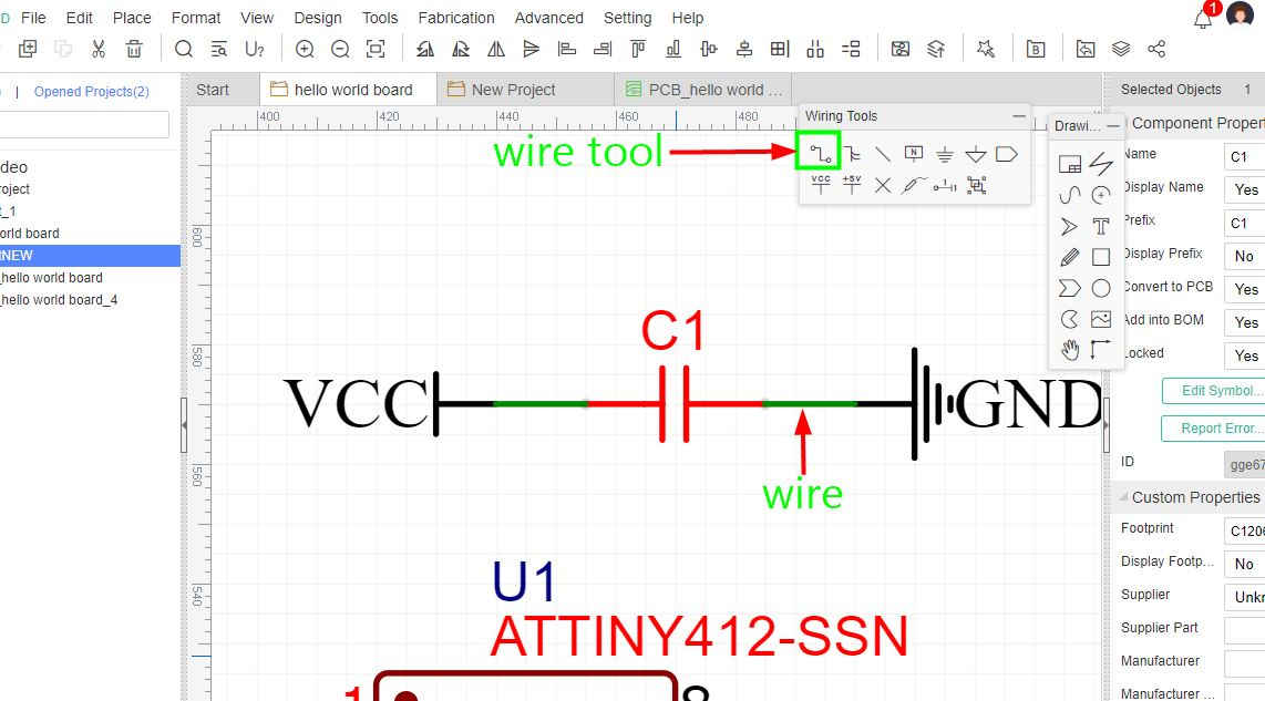
In order to connect the components together from the tools menu I selected the wire tool and connected the components from point to point.
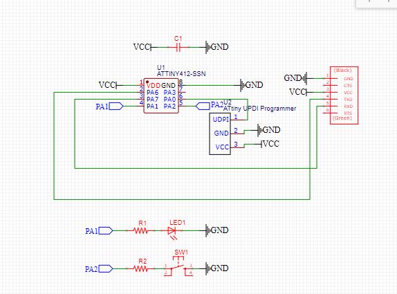
The schematic below shows all the wiring for the circuit.
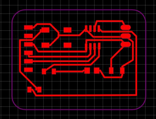
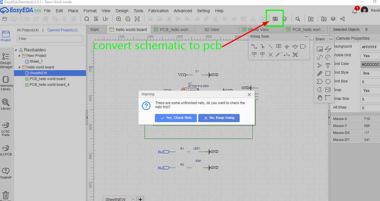
After completing the schematic i clicked convert schematic to pcb as shown in the image below.
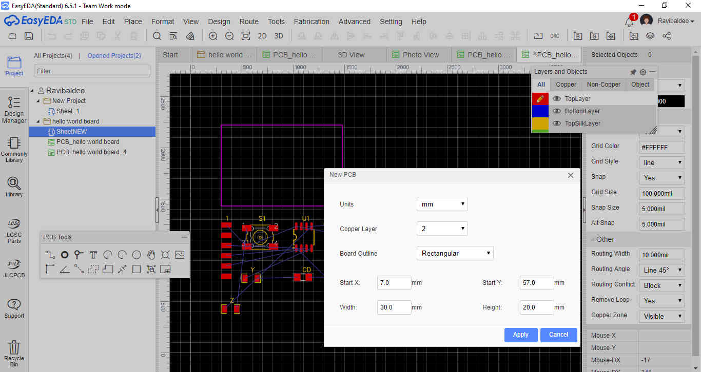
After the conversion of the schematic the components first appear as in the image below. In the design rules i used 16 for the routing of the track width and can be changed to the panel on the right hand side.The purple outline that is seen aroung the circuit is called the board outline layer and can be altered in the software as well to suit the user.
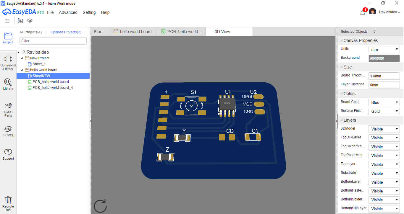
I was also able to simulate a 3D version of the board
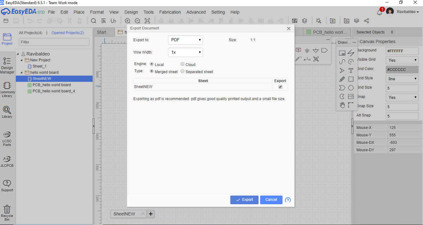
There are three options when exporting the file as follows:
- PNG
- SVG
I exported the file as a PDF since that is the one that gave the best results.
I went to file > export >pdf.
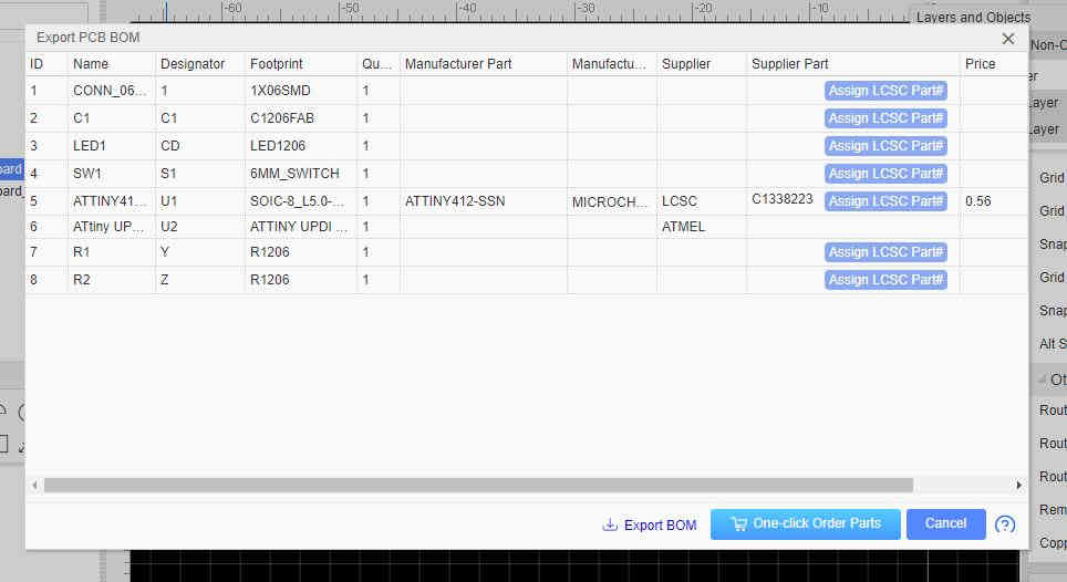
Also i was able to export a bill of materials list for the circuit.
Hero Shot