9. Embedded programming
Hello! this time, let’s learn about embedded programming. Today I will try to explain the information I was able to gather about the ATtiny44 how it works when programmed and about two computer architectures, Von Neumann and Harvard Architecture.
Von Neuman and Harvard architecture
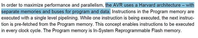
The main difference between the two architectures is that in a Von Neumann architecture all memory is capable of storing all program elements, data, and instructions; In a Harvard architecture the memory is divided into two memories, one for data and one for instructions.
harvard architecture
The organization of the computer according to the Harvard model, basically, is distinguished from the Von Neumann model by the division of the memory into an instruction memory and a data memory, so that the processor can access the two memories separately and simultaneously. It results in a loss of space, because if there is space left in the data memory, the instruction memory cannot use the space in the data memory and vice versa.
vonneuman architecture
The von Neumane architecture is a design that uses memory to store instructions and data. This type of machine is the implementation of a Turing machine and the vision of a sequential rather than parallel architecture. With this model (Neuman machine) the concept of stored program arises, for which computers of this type are also known. The von Neumann architecture is generally used in literally all machines, from desktops, laptops, high performance computers to workstations. In conclusion, we can say that our microcontrollers have Harvard Architecture. In my case I am using an ATtiny44, and if we review its technical sheet, we can confirm the following data provided by the manuals.
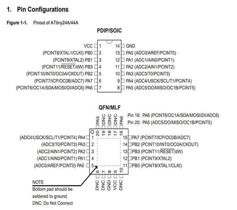
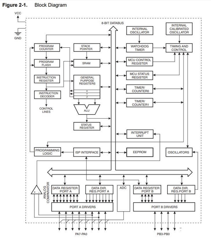
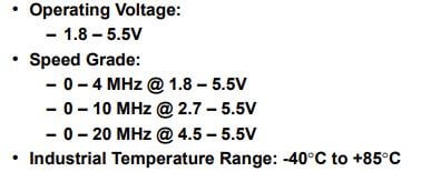
Some important data that we can find in the datasheet are: pin configurations, the block D diagram and also the operating voltage and speed rating. Here I share the technical sheet of the ATtiny44.
Programming the ATtiny44
Before starting to program, we must know the communication protocol, in this case it is ISP (In-System Programming), and identify the communication pins in each device.
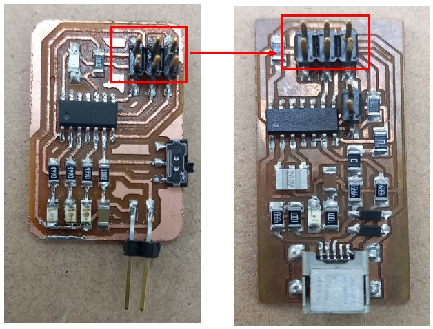
How it can be seen in the following image is the way to install the PCI programmer and the other device that was carried out in the laboratory.
Then we can use the Arduino IDE to start programming, but remember that the pins and their order have a different assignment in Arduino, it is recommended to review the ATtiny44 technical sheets in the following image.
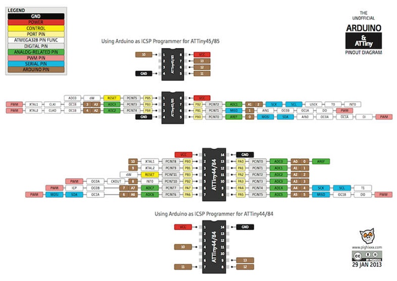
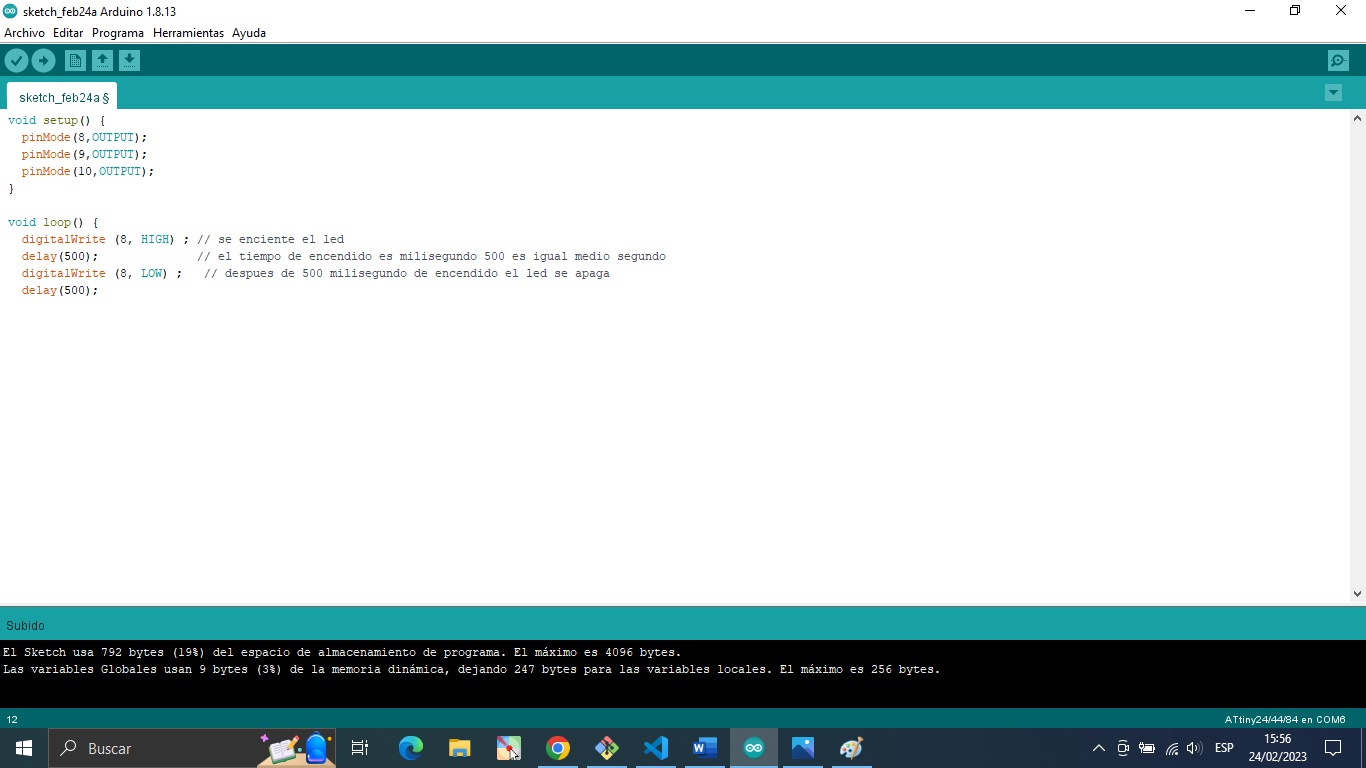
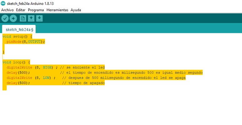
For example, the physical pin number 5 of the ATtiny44, in Arduino it would be programmed as pin number 8. The code used is the following: void loop() { digital write(8, HIGH); // the led lights up delay(500); // ignition time is millisecond 500 equals half a second digital writing (8, LOW); // after 500 milliseconds of ignition the led turns off and performs the same route turns on turns off for the programmed time
Code for ATtiny44
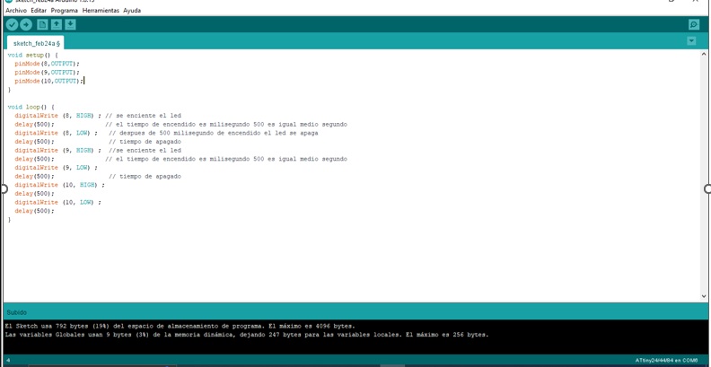
Let’s explain the code… In the first part we declare variables, specifically 3 variables, one to read the state of the switch, another for the state of the phototransistor and another for the number of the pin that will turn on a led (in this case my board has 3 leds, connected in the pins 8, 9 and 10, that’s why I start at 8), the last variable is to record the time that elapses
The next section is where we define some configuration parameters of our ATtiny44. pin 3 corresponds to the phototransistor and pin 7 to the switch, that is why we both declare them as inputs, and for their part, pins 8, 9 and 10, correspond to the 3 leds on the board, that is why we declare them as outputs.
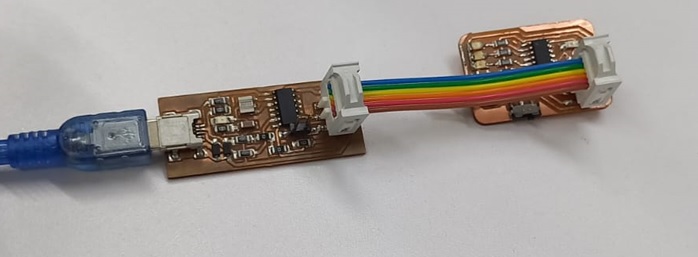
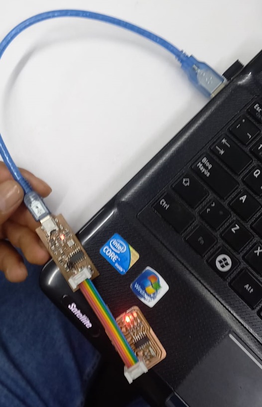
We already observed the design and operation of this board in the previous task. But the question is: how to load this code? The first thing is to connect our circuit and our programmer to the PC and then load the programming with the Arduino for its operation, it can be seen in the image how our circuits should be cone
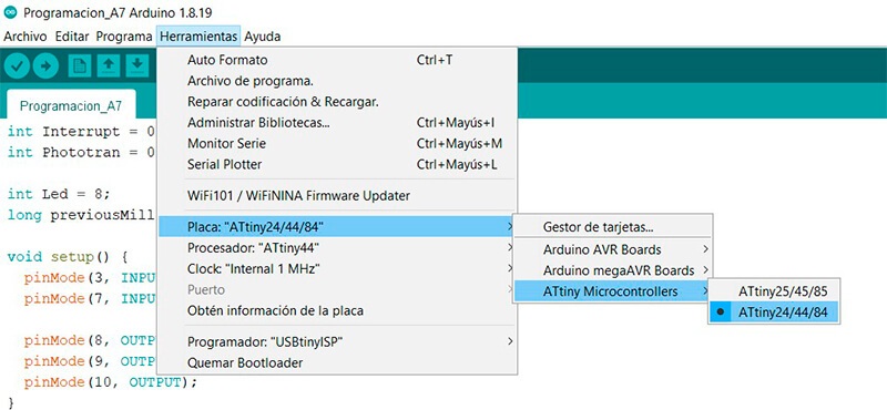
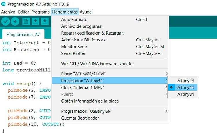
My code is a traffic light that is paused by a switch or when the light of a phototransistor is blocked. The first thing we must do is the board or family of our microcontroller, we do this in the “tools” menu. In our case it is “Attiny24/44/84”
Finally, we select our programmer, we have a USBtinyISP
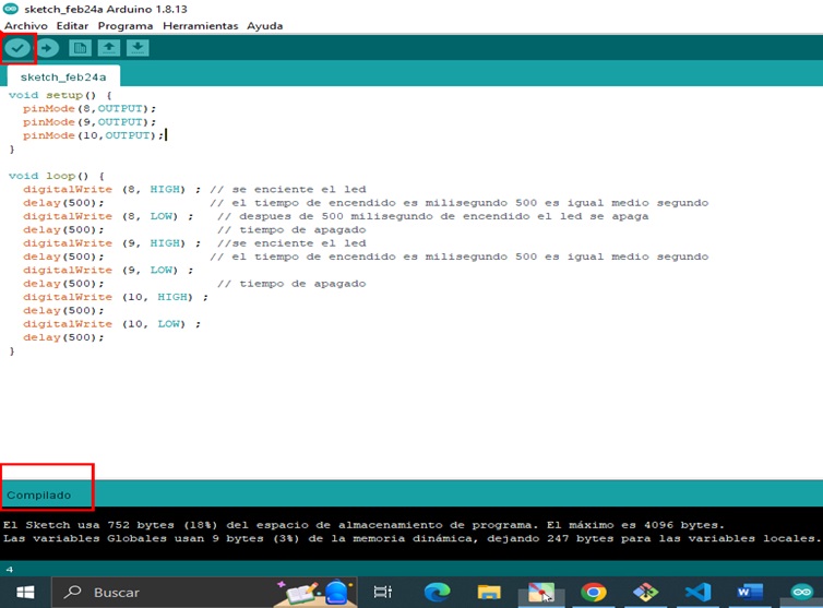
We can also compare our code, to see if there are any errors.
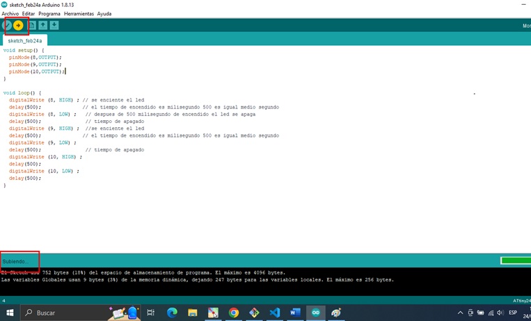
Now, we click on upload, and wait a few seconds, if everything went well, we can see a very satisfactory message that says: uploaded.
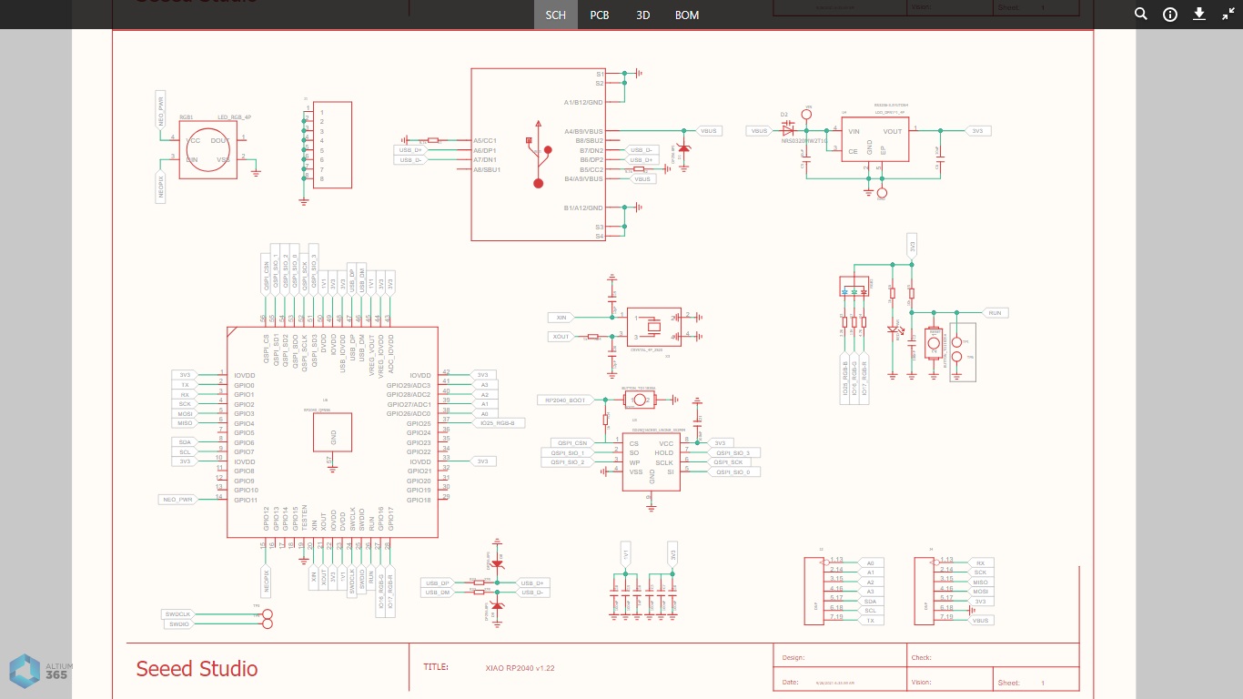
PROGRAMMING SEEED XIAO – RP2040
Before starting to program we must know the communication protocol, A microcomputer board using the Raspberry Pi Foundation’s RP2040 chip (dual-core Arm Cortex-M0+). It operates up to 133 MHz and packs a rich interface on a thumb-sized board. It is powerful and consumes less power, making it suitable for making portable devices and small devices.
In addition to the CPU, it has 2 MB flash, 11 digital pins, 4 analog pins, 11 PWM pins, and I2C/UART/SPI/SWD interfaces (1 each) (multi-function (have multiple pins).
It also supports a USB Type-C interface, which can be used to supply power and write code. It also has a reset button, home button, programmable RGB LED, power LED, two status indicators, and user-defined LEDs for easy debugging.
All the components are soldered on one board, which makes it very compact. Soldering this product to your own PCB is also easy. The XIAO RP2040 pins are compatible with Seeeduino XIAO, so you can also use the Seeeduino XIAO expansion board for development.
PROGRAMMING SEEED XIAO – RP2040
Before starting to program, we must know the communication protocol and identify the communication pins in each device.
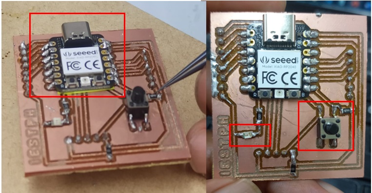
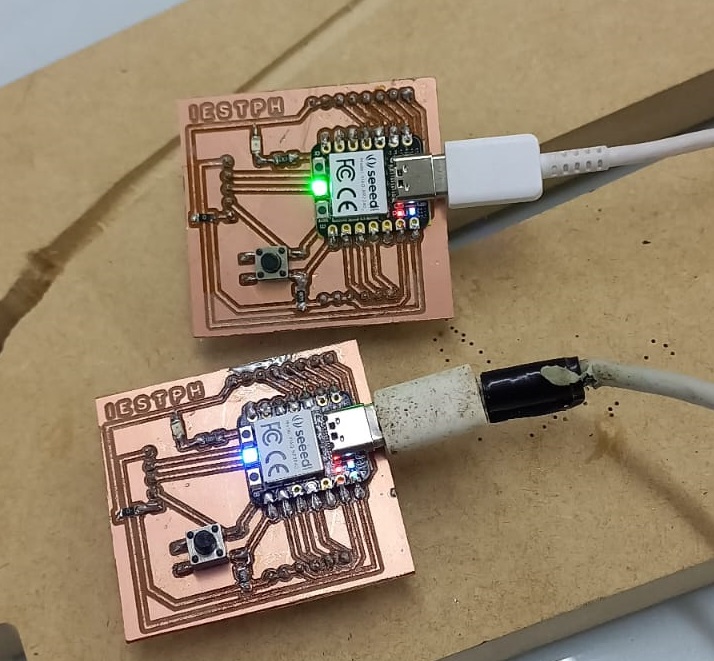
Having already prepared the XIAO - RP2040 circuit, we proceed with the connection to the USB port and it is observed that the LEDs of the device light up.