7. Electronics design
INTRODUCTION This week’s homework is important to me. As a technical professional in production mechanics, I have very little knowledge of electronics. I need to learn to develop electronic projects with my students within the institution where I work. For a long time I tried to understand how electronic projects can be carried out, such as making electronic circuits and by watching some videos I understood the importance of this work, the fear of not fulfilling the projects is due to the lack of electronic components within my town, they are very scarce to get components for this reason is limited to the development of electronic projects. But with the Fab Academy course, to execute the project and the tasks, I need to learn more about electronics that is my challenge. This homework is important because I will learn about the use of electronic components, circuit design, and how to solder circuits together.
Research
BASIC ELECTRONIC
An electronic circuit consists of a structure of plates formed by semiconductor materials, active and passive materials, whose function is to create a complete path through which the current can travel. It depends on the flow of electrons for the generation, transmission, reception and storage of information. In everyday applications, this information can consist of a voice or music as data in a computer. To be a loop, this path must start and end at the same point. In other words, a circuit must form a loop. An electronic circuit and an electrical circuit have the same definition, but electronic circuits tend to be low voltage circuits.
ALL THE CIRCUITS CAN BE MADE UP OF THREE BASIC ELEMENTS:
Voltage source: it is the one that gives the current to the electronic circuit. They are also called power supplies. Load: It is a device that consumes electrical energy in the form of current and transforms it into other forms. Without the load, there’s not much point in having a circuit. In complex circuits, the load is a combination of components, such as resistors, capacitors, transistors, etc. Conductive Path: Provides a path through which current flows. This path starts at the voltage source, travels through the load, and then back to the voltage source. This path should loop from the negative side of the voltage source to the positive side of the voltage source.
ACTIVE ELECTRONIC COMPONENTS
They are those that supply energy to a circuit. Examples: semiconductors, power supplies.
PASSIVE ELECTRONIC COMPONENTS
They are those that do not generate energy, but rather store and/or release it. Examples: resistors, capacitors, diodes, inductors.
TYPES OF ELECTRONIC CIRCUITS
• ANALOG CIRCUITS Analog circuits use a series of currents and voltages that continually change their value over time. To do this, it makes use of alternating current or values which always have the same value of voltage and intensity. Its components are the resistors, the potentiometer, the diode, the LED diode, the capacitor and the transistor. • DIGITAL CIRCUITS They use electrical currents and voltages which can only have two states over time. These states are with or without current or voltage. From a numerical point of view they use the binary code, that is, these circuits work with two values depending on whether there is current or not.
APPLICATION IN INDUSTRIAL ELECTRONICS
The electronic circuits are in the printed circuits. These are the surface into which the electronic components are embedded. The surface is formed by paths of conductive material laminated on a non-conductive base. The electrical circuit together with the printed circuit forms the famous electronic cards or PCBS. PCBs are used in manufacturing industries, especially those with high power machinery and equipment and require high current circuitry to function. It depends on its components will do one thing or another. We find PCBS in industrial computers, machines, screens, etc.
BASIC ELECTRONIC COMPONENTS
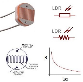
PHOTO RESISTANCE.
A photoresistor is a resistance whose value in ohms varies with variations in light. These resistors are made of a light-sensitive material, in such a way that when light falls on its surface, the material undergoes a chemical reaction, altering its electrical resistance.
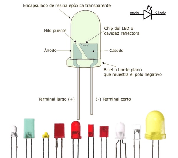
LED DIODE.
An LED diode is a device that allows the passage of current in only one direction and that, when polarized, emits a beam of light. It works like a normal diode, but when receiving electric current it emits light. The LEDs work approximately with 2V current.
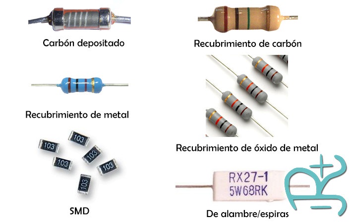
ENDURANCE.
Electrical resistance is a measure of how difficult it is to carry an electrical current through the electrical conductor. Free electrons move randomly within a conductor. Electrons collide with other atoms and molecules in the conductor when an electrical potential is applied to it. Component used to create a resistance to the flow of a load called a resistor. A resistor is a two-terminal passive electrical component that implements electrical resistance as a circuit element. In electronic circuits, resistors are used to: • reduce current flow • adjust signal levels • divide the voltages. we cannot connect the switch/button directly to the microcontroller because when the switch is not pressed, the input to a microcontroller has a high impedance state, which means that the input to a microcontroller can either be logic ‘0’ or logic 1’. To get around this, we use a resistor called a pull-up resistor or pull-down resistor.
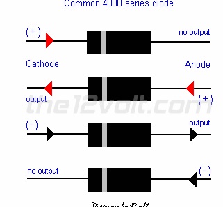
DIODE
A diode is a semiconductor device that essentially acts as a one-way switch for current. It allows current to flow in one direction, but does not allow current to flow in the opposite direction.
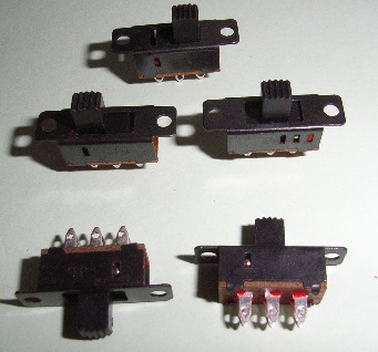
SWITCH
The operation of the switch is based on opening the circuit at a certain point, cutting the flow of current through the conductors. The fundamental parts are the connectors and the actuator.
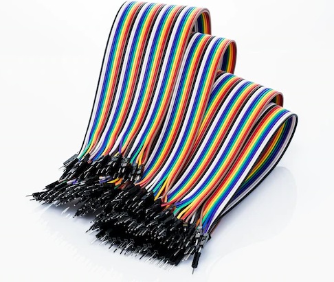
FLAT CABLE
Flat cable, also known as stranded flat cable, is used for a wide variety of high-speed, high-performance, space-constrained, and low-voltage applications.
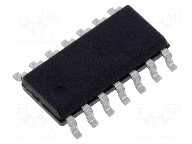
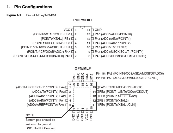
ATTINY44 MICROCONTROLLER
ATtiny (also known as TinyAVR) is a subfamily of the popular 8-bit AVR microcontrollers. AVR is a family of microcontrollers created by Atmel in 1996. These are 8-bit RISC single-chip microcontrollers with a modified Harvard design. AVR is one of the first microcontroller families to use on-chip flash memory for program storage.
ATTINY44 SPECIFICATIONS
The ATTINY44-20PU is a low power 8-bit CMOS microcontroller based on AVR’s Enhanced RISC architecture. By executing powerful instructions in a single clock cycle, the ATtiny44 achieves performances approaching 1 MIPS per MHz, allowing the system designer to optimize power consumption versus processing speed. The AVR core combines a rich instruction set with 32 general-purpose work registers. The 32 registers are directly connected to the Arithmetic Logic Unit (ALU), allowing two independent registers to be accessed in a single instruction executed in one clock cycle. The resulting architecture is more efficient in code and achieves performance up to ten times faster than conventional CISC microcontrollers. The ATtiny44 provides 4kB of system programmable flash, 256 byte EEPROM and 256 byte SRAM. The device supports a performance of 20 MIPS at 20 MHz.
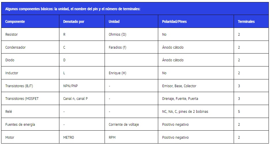
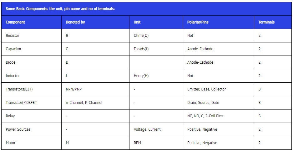
SOME BASIC COMPONENTS: THE UNIT, THE NAME OF THE PIN AND THE NUMBER OF TERMINALS:
ATTINY44 MICROCONTROLLER
ATtiny (also known as TinyAVR) is a subfamily of the popular 8-bit AVR microcontrollers. AVR is a family of microcontrollers created by Atmel in 1996. These are 8-bit RISC single-chip microcontrollers with a modified Harvard design. AVR is one of the first microcontroller families to use on-chip flash memory for program storage.
ATTINY44 SPECIFICATIONS
The ATTINY44-20PU is a low power 8-bit CMOS microcontroller based on AVR’s Enhanced RISC architecture. By executing powerful instructions in a single clock cycle, the ATtiny44 achieves performances approaching 1 MIPS per MHz, allowing the system designer to optimize power consumption versus processing speed. The AVR core combines a rich instruction set with 32 general-purpose work registers. The 32 registers are directly connected to the Arithmetic Logic Unit (ALU), allowing two independent registers to be accessed in a single instruction executed in one clock cycle. The resulting architecture is more efficient in code and achieves performance up to ten times faster than conventional CISC microcontrollers. The ATtiny44 provides 4kB of system programmable flash, 256 byte EEPROM and 256 byte SRAM. The device supports a performance of 20 MIPS at 20 MHz.
SOME BASIC COMPONENTS: THE UNIT, THE NAME OF THE PIN AND THE NUMBER OF TERMINALS:
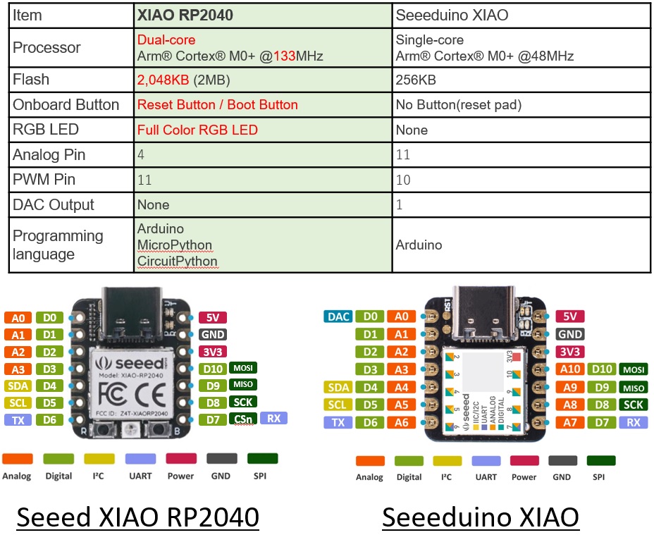
SEEEDUINO XIAO-RP2040
Description
The Seeeduino XIAO device. It is the smallest member of the Seeeduino family. Seeeduino XIAO still carries the powerful CPU-ARM® Cortex®-M0+(SAMD21G18), which is a low-power Arduino microcontroller. On the other hand, this small board has good processing performance, but requires less power. In fact, it is designed in a small size and can be used for Arduino handheld devices and small projects. Apart from the powerful CPU, Seeeduino XIAO is excellent in many other features. It has 14 GPIO PINs, which can be used for 11 analog PINs, 11 digital PINs, 1 I2C interface, 1 UART interface, and 1 SPI interface. Some pins have multiple functions, pins A1/D1 to A10/D10 have PWM functions, and pin A0/D0 has a DAC function, which means you can get true analog signals, not PWM signals when you define it as an analog pin. , that’s why 14 GPIO PINs can realize more interfaces and I/O PINs. In addition, Seeeduino XIAO supports USB Type-C interface which can supply power and download code. There are power pads on the back of the XIAO that support the battery and make it designed to make portable devices realistic. Seeeduino XIAO is perfectly compatible with Arduino IDE, you can easily develop some small projects with the help of the large and comprehensive Arduino library. So get one and you will soon love it!
Key Features:
Powerful CPU: ARM® Cortex®-M0+ 32bit 48MHz microcontroller (SAMD21G18) with 256KB Flash,32KB SRAM Flexible compatibility: Compatible with Arduino IDE Easy project operation: Breadboard-friendly Small size: As small as a thumb(20x17.5mm) for wearable devices and small projects. Multiple development interfaces: 11 digital/analog pins, 10 PWM Pins, 1 DAC output, 1 SWD Bonding pad interface, 1 I2C interface, 1 UART interface, 1 SPI interface.
Specification:
• CPU: ARM Cortex-M0+ CPU(SAMD21G18) running at up to 48MHz.
• Storage: 256KB Flash,32KB SRAM
• I/O PINs: 14 GPIO PINs,11 analog PINs, 11 digital PINs, 1 DAC output Pin
• Interface: 1 I2C interface,1 UART interface, 1 SPI interface
• Power supply and downloading interface: USB Type-C interface
• LEDs: 1 user LED, 1 power LED, two LEDs for serial port downloading
• Reset button: two reset button short connect to reset
• Power Pads: For the battery power supply
• Software compatibility: Compatible with Arduino IDE
• Projection cover for protecting the circuit
• Dimensions: 20x17.5x3.5 mm
Typical Application:
• Wearable devices
• Rapid prototyping (directly attached to the expanded PCB as a minimal system)
• Perfect for all the projects need mini Arduino
• DIY keyboard
• USB development (USB to multi-channel TTL/USB host mode, etc.)
• A scenario where you need to read multiple mock values The DAC output
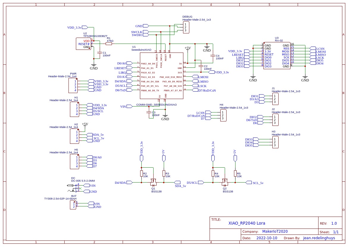
What features are on the PCB?
All of the Xiao RP2040’s pins and pads are broken out onto the PCB, including the SWD port. The Xiao also has a user LED, and a NeoPixel on-board, which can easily be used for signal indication. Level shifted 5v I2C port, in addition to the standard 3.3v I2C, because all of our sensors are not always 3.3v compatible, and using external level shifters is not always so convenient. Access to the RA-02’s GPIOs (DIO1-DIO5) is provided, but most people won’t need to worry about these. Jumpers to connect some of the Xiao RP2040 GPIO to the special use GPIO on the RA-02, for example, GPIO1 and GPIO2, sometimes used with some of the more specialised LoRa libraries. Provision or powering the device via a dc barrel connector, or screw-terminal, as well as via the 3v input pins (make sure your supply has a capability of more than 300mA) A power management chip to reset the Xiao RP2040 when the supply voltage falls below 3.0v – To prevent unstable operation and possible lock-up.
The Schematic
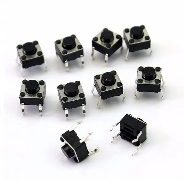
ELECTRONIC PUSH BUTTON
The buttons are generally activated by being pressed with a finger. They allow the flow of current while they are actuated. When you no longer press on it, it returns to its rest position. It can be a normally open contact at rest NO (Normally Open), or with a contact NC (normally closed) at rest.
TECHNICAL CHARACTERISTICS
Rated current: 50mA
Rated voltage: 12VDC
Size: approx. 6x6x5mm
Button height: approx. 3.1mm-13mm
Insulation resistance: > 100M ohm 250V DC
Withstand voltage: 250 VAC in 1 minute
Contact resistance: <100m ohm
Soldering temperature: 240 ° C Max in 3 seconds
Ambient temperature: -25 degrees C ~ +70 degrees C
Ambient humidity: <85% RH
Operating force: 180 +/- 50 gf
PRODUCT CONTENT
01 x Tactile pushbuttons 6x6x5 mm
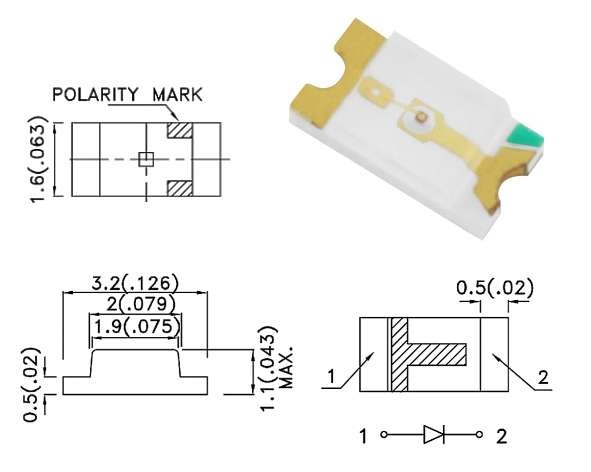
Würth Elektronik SMD LEDs
Würth Elektronik SMD LEDs are Surface-Mount Technology (SMT) mono-color chip LEDs with a water-clear lens designed to allow more flexibility for miniature and portable devices. These LEDs feature low energy consumption, low current requirements, and high reliability. The Würth Elektronik SMD LEDs are available in blue, green, bright green, yellow, amber, red, and super red colors. These LEDs are available in the industrial standard 0603 domes, super-flat, and advanced package sizes with additional package size in 0805 and 1206.
FEATURES
Low energy consumption High reliability Low current requirement Fast switching Small SMT LED package for exceptional brightness Top view LED No UV/IR radiation Wide viewing angle Better solder ability Heat dissipation
APPLICATIONS
Backlight for mobile and portable device keypads Indoor and outdoor message boards Flat backlight for LCDs, switches, and symbols Display for industrial control systems and traffic Miniaturized color effects Pedestrian mark Optical indicators Backlight for automobile DVD Tabular backlight: LCD Telephone key-press Power-switch Display board Indoor displays Signals Identifiers