5. Electronics production
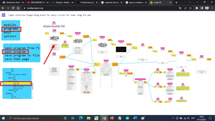
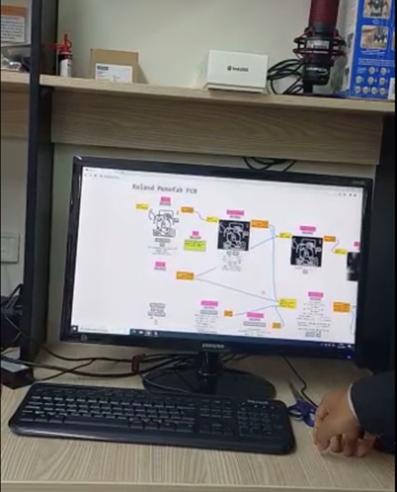
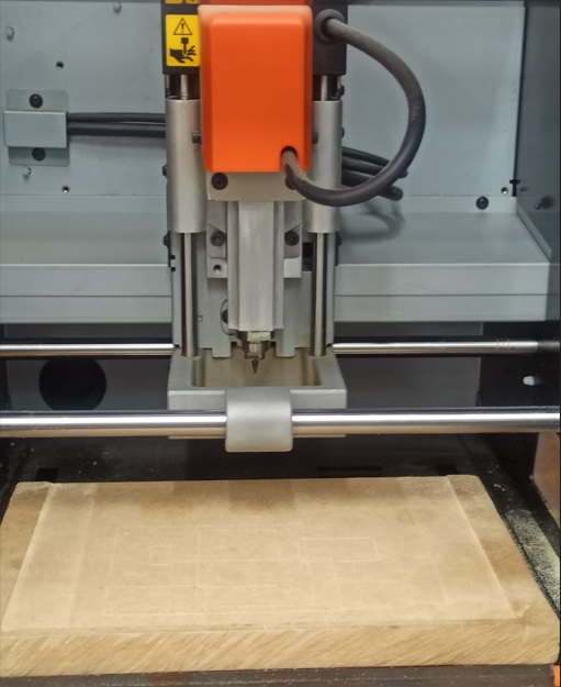
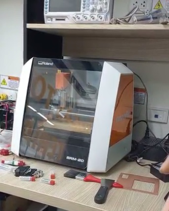
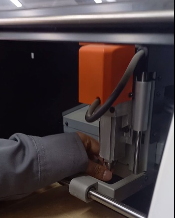
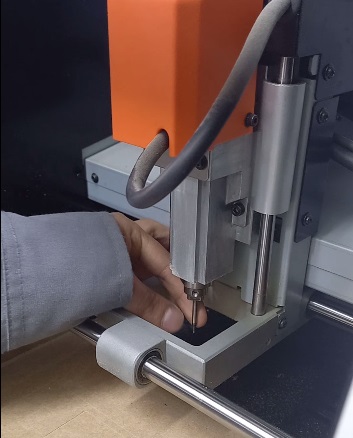
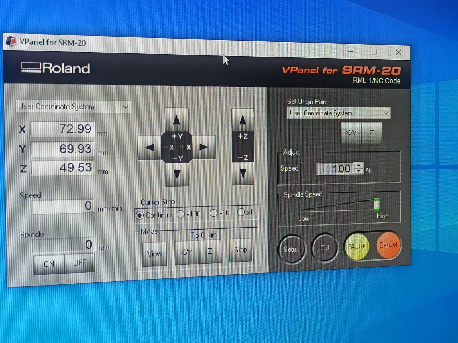
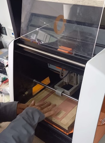
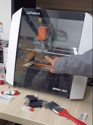
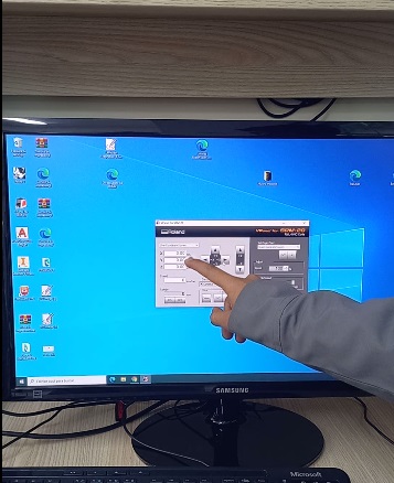
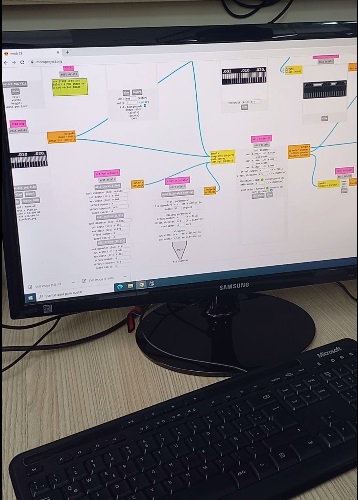
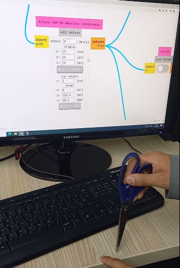
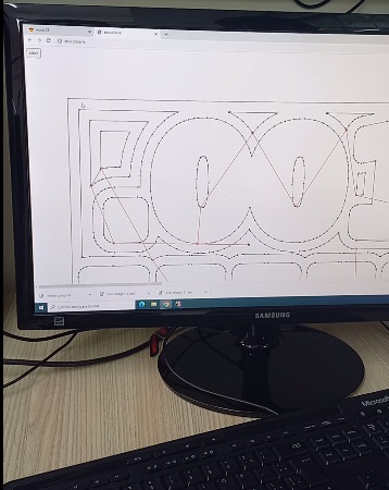
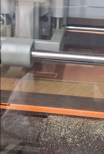
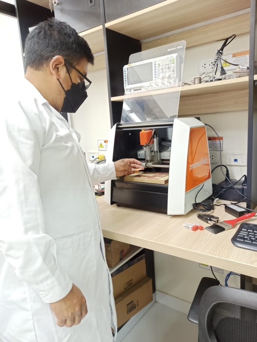
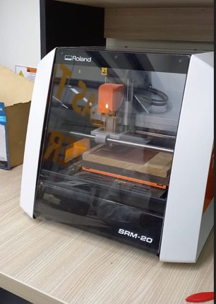
CHARACTERIZE THE DESIGN RULES FOR YOUR IN-HOUSE PCB PRODUCTION PROCESS: SPEEDS, PENETRATION RATE, DEPTH OF CUT (SCREENS AND CONTOURS), AND TOOLING. This week we start with the group task. The instructor instructed us on the PCB milling machine, its setup, and modification projects. In our Fab Lab, we have the Mono fab milling machine. We are using this machine for PCB milling. Fab academy has delivered the sketches - Line Test and Interior for the precision test of the PCB milling machine. Using mods project, we have generated the trajectory. The tool path is loaded into the VPanel for SRM-20 to make the design cuts on the board. We have cut the PCB copper foil into a size of 60mm x 50mm. Double-sided tape is adhered to the back of the copper sheet and placed on the router bed. Next, we installed the 0.2mm end mill tool. for milling to trace the path on the PCB. Using the gravity technique, we make sure that the tip of the tool touches the top of the copper plate. And we set the tool position to [X,Y,Z]=[0,0,0] local coordinate system. After the scribing operation is complete, a 1/64” tool is placed in the collet and again using the gravity test procedure, we establish a coincident position of the tool nose with the mill bed as origin to cut the copper plate After finishing the operation, the material is cleaned with a brush to remove the dust from the plate and with the help of a spatula we proceed to remove the final product from the milling machine platform.
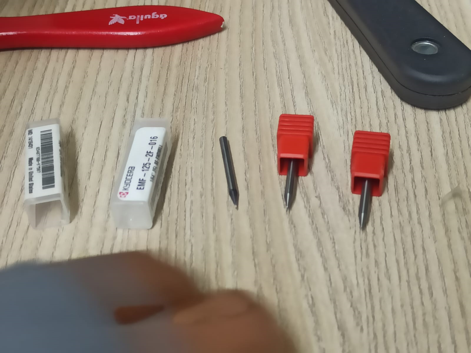
SELECTION OF STRAWBERRIES FOR WORK. In the group work, the first thing we did was select the appropriate milling cutters for the processes, the first milling cutter is 0.2 mm for milling where it makes four passes to remove the material, for cutting the PCB board it is 1/16” where it is done in three passes for cutting and having the result.
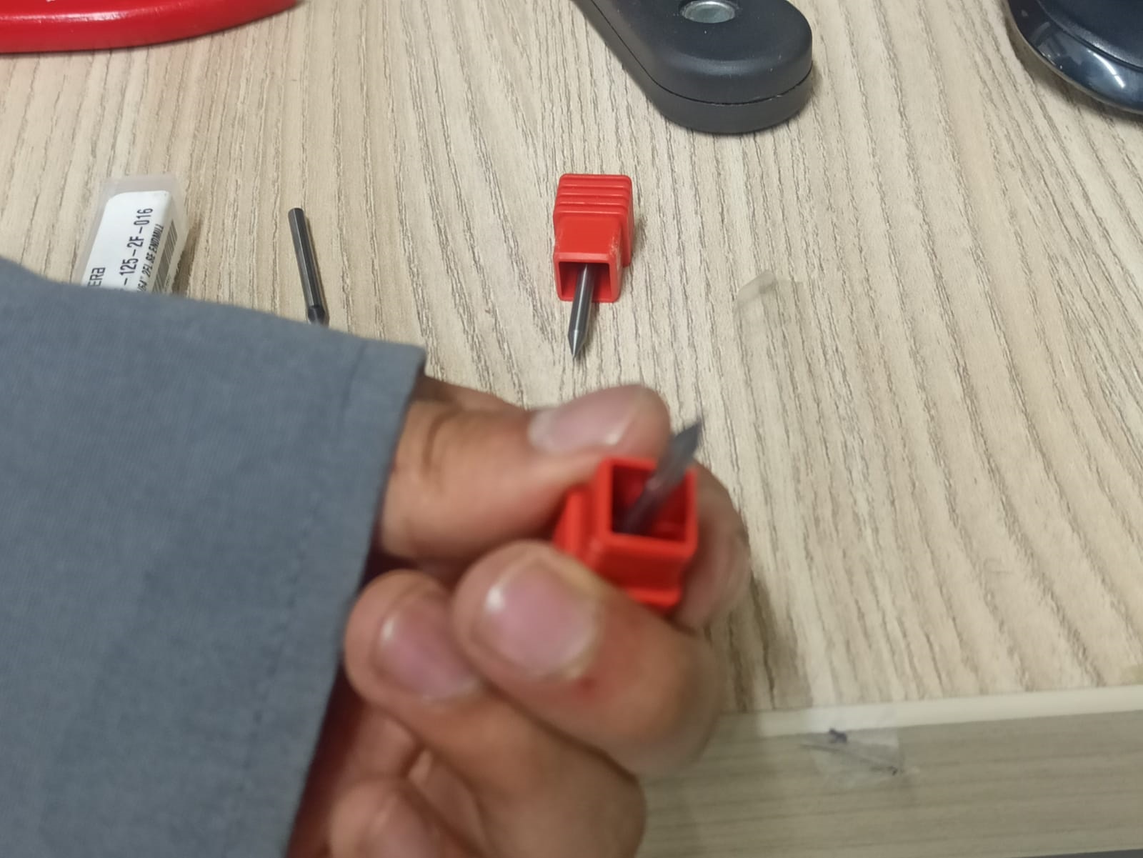
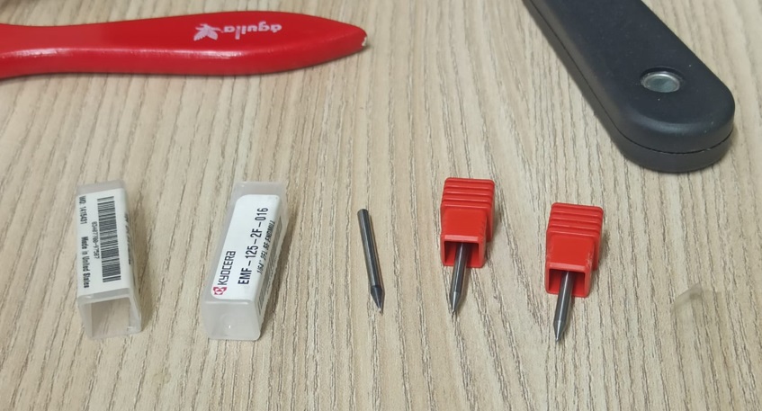
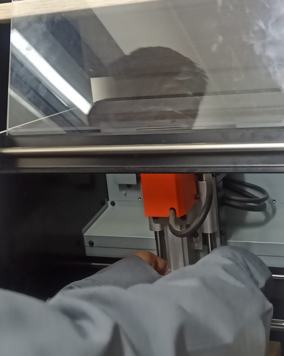
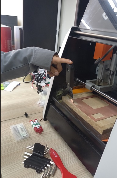
HOW TO INSTALL THE CUTTER IN THE MONO FAB MACHINE As worked on the PCB milling machine, first the milling cutter is placed for the milling process with the gravity technique, we make sure that the tip of the milling cutter hits the PCB plate to carry out the milling process and execute .
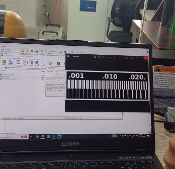
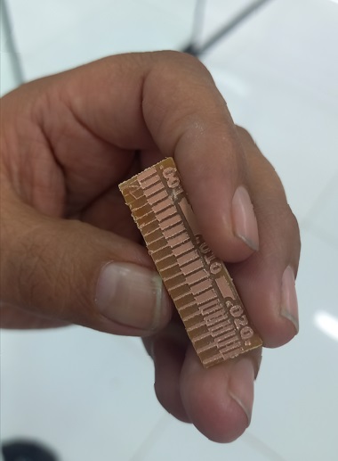
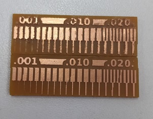
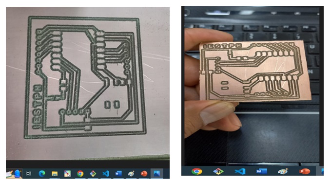
TEST WORK ON MILLED PCB In the milling process carried out in the mono fab equipment, the following milling parameters have been obtained, as observed in the images of .001, it could be deduced that it is not suitable for milling because the copper detaches due to being very thin, from .10 to .020 you could work for the execution of circuits and perform milling on PBC boards, personally I can perform milling from .020 because it is more resistant for assembling the circuit and soldering.
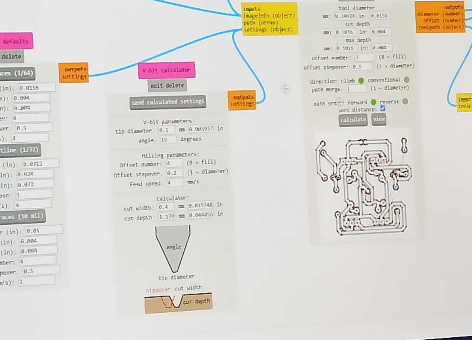
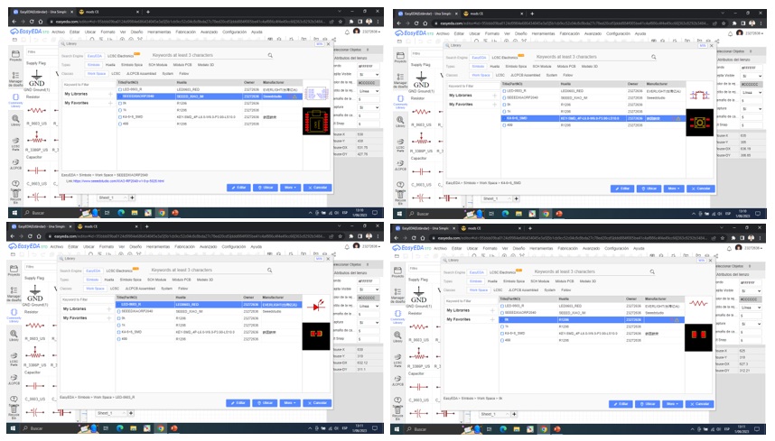
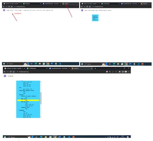
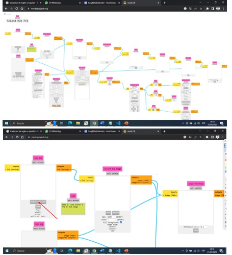
You start to design the circuit for the electronic component of the XIOA - RP2040 Using the CE mod programs.
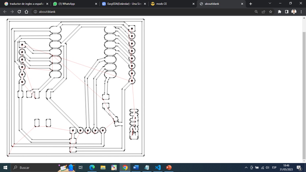
selection of components for the design of the plate and execution using the Easy EDA program.
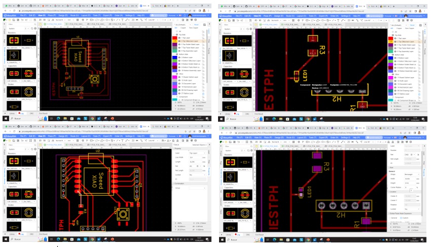
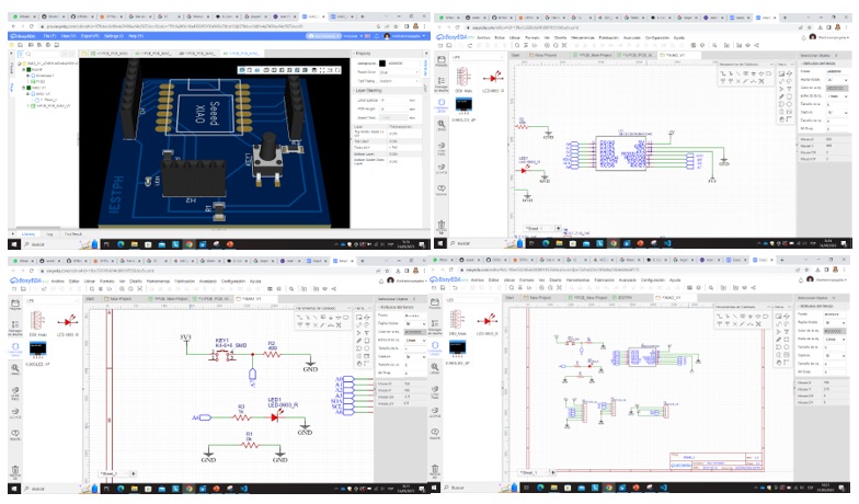
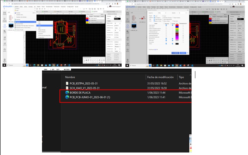
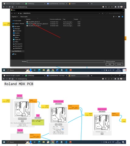
After making the design in Easy Eda, we proceed to send the circuit in SVG format to engrave the circuit in the mold.
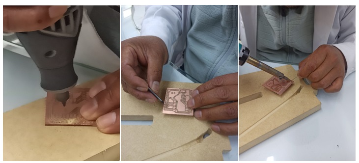
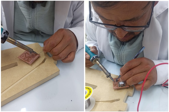
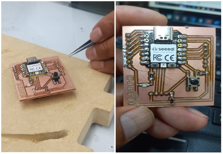
After the design, the cutting process is carried out on the machine using the 1/32 and 1/64 bits, one for cutting and the other for tracing the bakelite. After doing the work, the components are soldered with the soldering iron and the lead. for its funtionability.
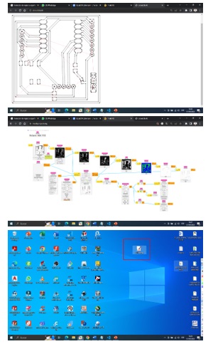
The engraving of the circuit design begins in the phono lab machine and proceed to soldering.
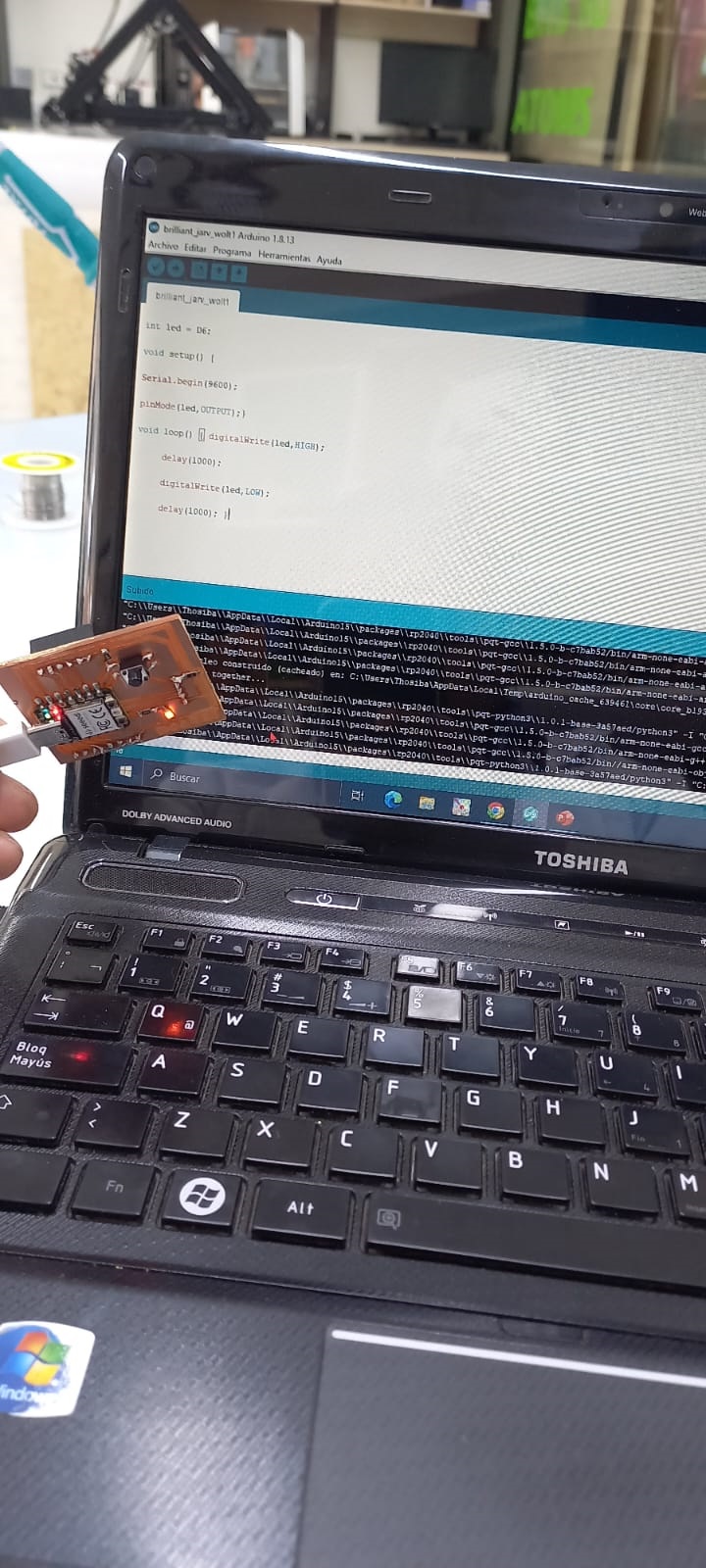
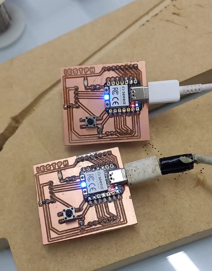
We begin to carry out the tests of the circuit connecting to the computer where the lighting of the leds is observed.
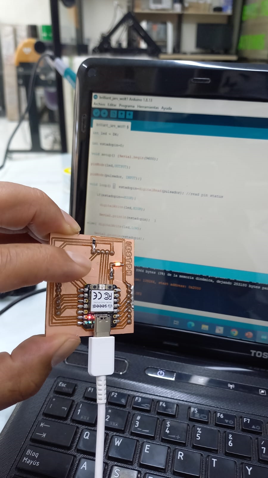
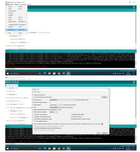
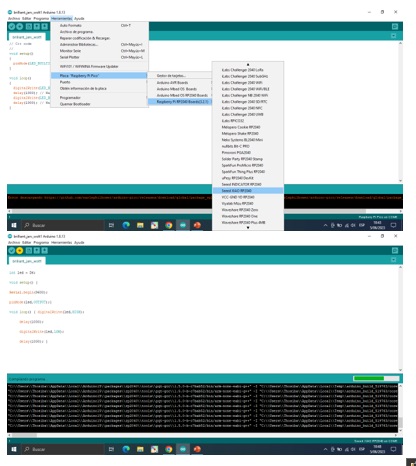
Now we proceed to install the XIAO RP2040 libraries in the arduino to carry out the programming and verify that it works with the button.
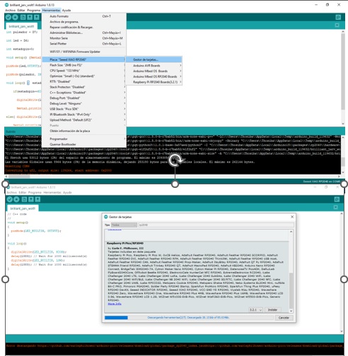
Now we proceed to carry out the programming of the led and it is observed when a pulse is made, the led lights up, stops pressing the led goes out and indicates that the installation and the soldering of the circuit are correct.