8. Computer controlled machining
This week I designed and machined a foldable table.
Group Assignment
The most important thing when dealing with large scale machines is keeping in mind safety precautions, which are shown below:
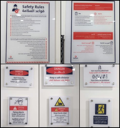
The main instruction is to stay away from the machine. Also, not to let long stuff (like hair) hanging around the machine.
Machine and Tools
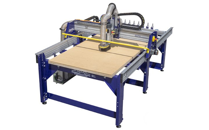
In this assignment we used the ShopBot PRSalpha ATC 96-60-8 CNC machine, whose specifications are listed below: Specs:
- Cut/Movement Area (Length x Width x Plunge): 105” x 61” x 8” (2.67m x 1.55m x .2m)
- Step Resolution: 0.0004” (0.010mm)
- Positional Repeatability: +/- 0.002” (0.051mm)
- Spindle RPM: Max 18,000 RPM
- XY Move Speed (with full cutting force): Max 360”/min (9.1m/min)
- Z Move Speed (with full cutting force): Max 120”/min (3m/min)
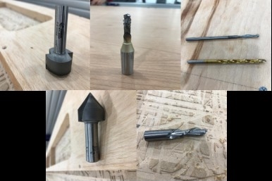
Tools
We saw 5 end mills, listed and indicated below, with each having its applications. However, in this assignment we used two tools only.
- 91-000 Carbide Tipped - Spoilboard Surfacing
- Solid Carbide router, 2 flute, downcut
- 60-100PLR Solid Carbide - Polaris Compression
- Carbide Tipped router, 2 flute, V Bottom
- Solid Carbide drill, 2 flute, 8 facet
Individual Assignment
For the individual assignment I decided to build a foldable and compact table for my too crowded room.
CAD
In order to do that I first designed its part using Fusion 360. As shown below, I 2D sketched the table’s section. Inspired by a LinkedIn post I wanted a 3-legged table whose legs can be folded too. So, in the design I made each leg consist of three separate parts. This ensured that the table was as compact as possible.
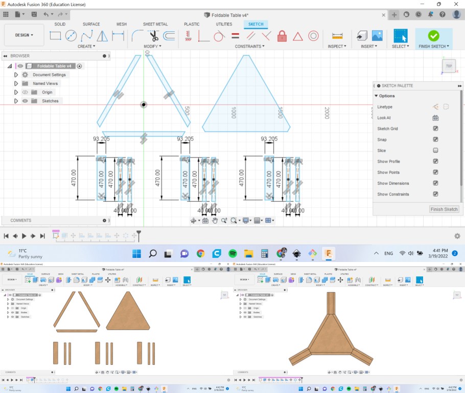
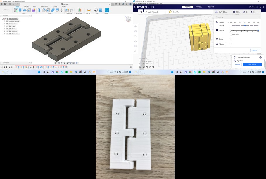
We did not have hinges at our lab. So, I thought why not try printing them in place, which worked fine.
CAM
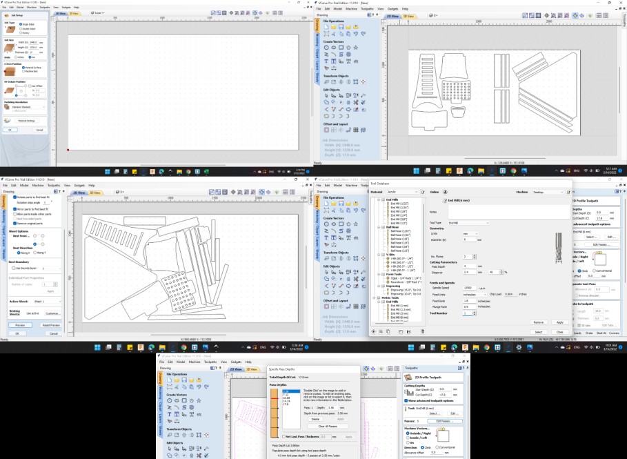
The CAM software I used in this assignment is V-Carve. After opening the software, I used was as follows:
- Job Type: Single Sided
- Job Size: 2440 mm x 1220 mm x 17.4 mm
- Z Zero Position: Material Surface
- XY Datum Position: Left-Bottom
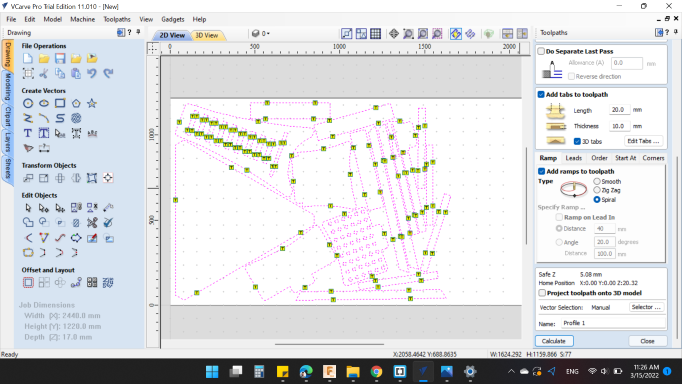
Then, I imported the drawings into the software. It is worth noting that for sake of time shortage my colleague Karam added his drawings too, and we cut our stuff in one job. Afterwards, in order to make best use of the board, we nested the drawings as shown below. In the nesting operation we specified the following settings
- Tool Dia. (D): 6 mm
- Clearance (C): 1 mm
- Boarder Gap: 30 mm –> To make sure the end mill does not collide with fastening nails
After that, we introduced the tool specifications to the software as follows:
- Metric Tools End Mill (6 mm)
- Diameter: 6 mm.
- No. of Flutes: 2.
- Cutting Parameters: Pass Depth: 2 mm, Stepover: 3.48 mm. / 58 %.
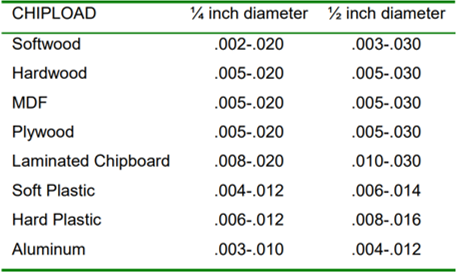
- Feeds and Speeds: Spindle Speed: 13500 r.p.m.. Chip Load: 0.004 inches, Feed Rate: 1.8 inches/sec, Plunge Rate: 0.9 inches/sec.
It is worth noting that the feed rate is calcualted as shown below:
𝐹𝑒𝑒𝑑 𝑅𝑎𝑡𝑒 (𝐼𝑃𝑀) = 𝑅𝑃𝑀 × 𝐶ℎ𝑖𝑝 𝐿𝑜𝑎𝑑 × # 𝑜𝑓 𝑐𝑢𝑡𝑡𝑖𝑛𝑔 𝑒𝑑𝑔𝑒𝑠
Then, we set the number of passes to 4, which means the machine will cut through the 17.8 mm board in 4 stages.
The last step is adding tabs. We did this automatically and specified that each part is to be held by 4 tabs.
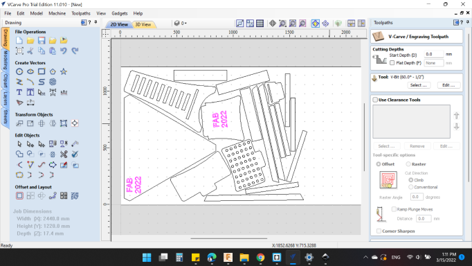
V-Carve
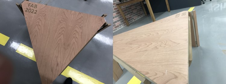
Another cool thing we did is that we used the V-Carve bit to write “Fab 2022” on our designs. We defined the tool as aforementioned.
Result
After the job was finished the result looked as illustrated below. In order to remove the tabs I used a multi-tool.
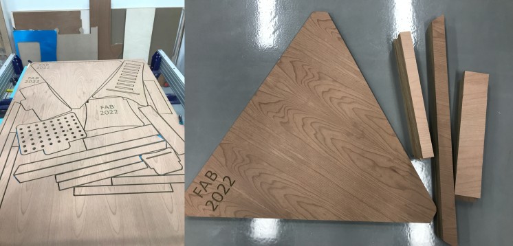
Hero Shot
After assembling the parts, the result looked as follows: