9. Embedded programming
This week’s assignment is to program the board previously designed, milled, and soldered in the Electronics Design week. To do so, we first need to read the ATtiny45 datasheet
Group Assignment
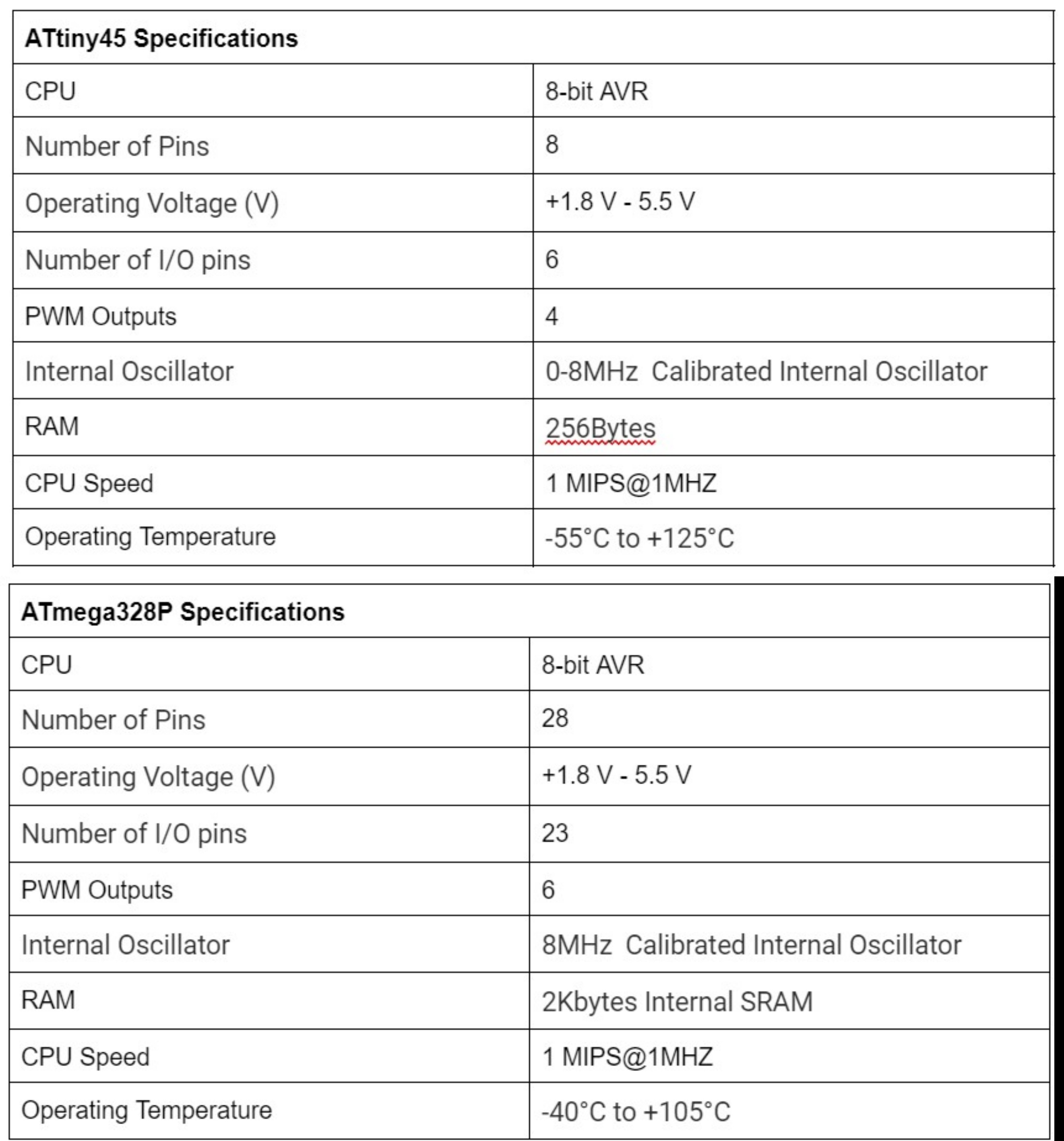
As part of the group assignment, we first need to compare different MCUs. So we decided to do a comparison between two AVR families: ATtiny45 from tinyAVR family and ATmega328P from megaAVR family.
Feature Comparison
The below table shows a comparison between ATtiny 45 and ATmega328p. Obviously, ATmega328p is more suitable for applications that require more processing.
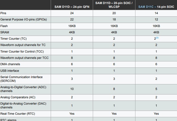
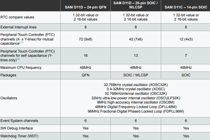
The following table also includes information about different Atmel chips such as SAM D11D and SAM D11C. The table is extracted from the data sheet. Clearly, the RAM in SAM chips is higher than ATtiny 45 and ATmega328p, which makes them more suitable for running multiple stuff at the same time or doing huge calculations.
Programming Using AVR-dude
I think the best way to explain this is how it is done here. Quoting “avrdude is a program that is used to update or read the flash and EEPROM memories of Atmel AVR microcontrollers on FreeBSD Unix. It supports the Atmel serial programming protocol using the PC’s parallel port and can upload either a raw binary file or an Intel Hex format file. It can also be used in an interactive mode to individually update EEPROM cells, fuse bits, and/or lock bits (if their access is supported by the Atmel serial programming protocol.) The main flash instruction memory of the AVR can also be programmed in interactive mode, however this is not very useful because one can only turn bits off. The only way to turn flash bits on is to erase the entire memory (using avrdude’s -e option).”
Programming Using Arduino
For this section too, I prefer quoting from an external reference: “Arduino IDE is a special software running on your system that allows you to write sketches (synonym for program in Arduino language) for different Arduino boards. The Arduino programming language is based on a very simple hardware programming language called processing, which is similar to the C language.”
Arduino C vs C
One of the questions I have always felt confused about is the difference between Arduino C and C. Now I know, Arduino C is basically C but with preprogrammed functions such as (Serial.read). Also, it is worth mentioning that C is faster and takes less time to be executed.
Individual Assignment
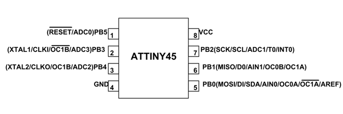
The board I designed has an ATtiny45 MCU. In order to program it let’s check the pinout in the datasheet.
Pinout Description
Now, let’s check the pinout description
- VCC: Supply voltage
- GND: Ground
- Port B (PB5:PB0): Port B is a 6-bit bi-directional I/O port with internal pull-up resistors (selected for each bit). The Port B output buffers have symmetrical drive characteristics with both high sink and source capability. As inputs, Port B pins that are externally pulled low will source current if the pull-up resistors are activated. The Port B pins are tri-stated when a reset condition becomes active, even if the clock is not running.
- Reset input: A low level on this pin for longer than the minimum pulse length will generate a reset, even if the clock is not running and provided the reset pin has not been disabled. Shorter pulses are not guaranteed to generate a reset. The reset pin can also be used as a (weak) I/O pin.
Programming via Arduino IDE
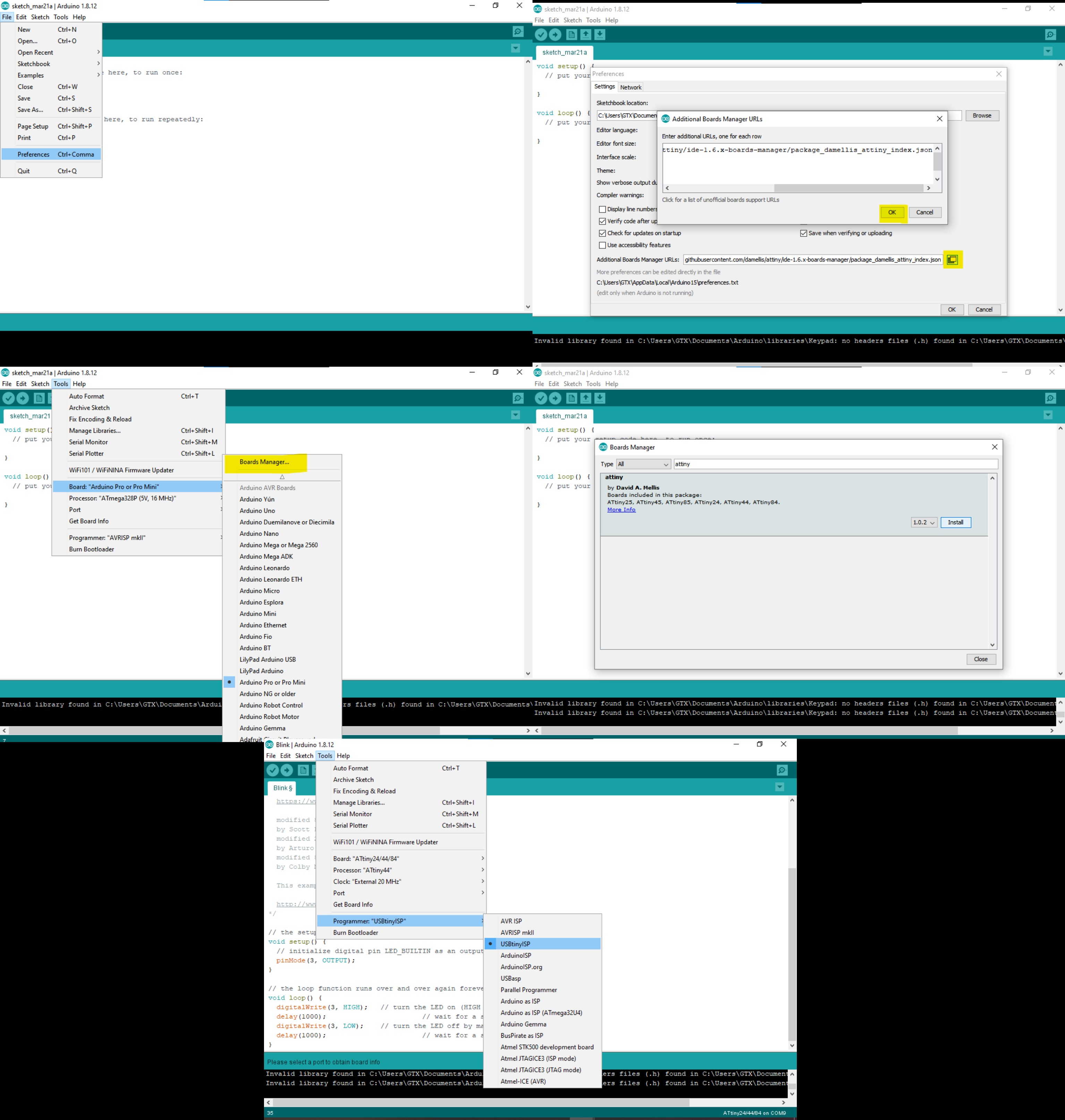
Depicted in the below picture, there are multiple steps required in order to program a micro-controller via Arduino IDE.
- First, in Arduino IDE, navigate to File –> preferences –> Additional Boards Manager URLs
- Then, paste the following link.
- Now, go to Tools –> Boards Manager
- Search for “attiny”, and install it
- Now, the micro-controller is installed. Go back to Tools, and choose your board (ATtiny45). Also, make sure you change the programmer to “USBtinyISP”.
Code
Code 1
Let’s try the following code
int buttonPin = 0;     // the number of the pushbutton pin
int ledPin1 =  4;      // the number of the LED pin
int ledPin2 =  1;      // the number of the LED pin

void setup() {
pinMode(ledPin, OUTPUT);

pinMode(buttonPin, INPUT); // initialize the pushbutton pin as an input:
}

// the loop function runs over and over again forever
void loop() {
   buttonState = digitalRead(buttonPin);

  // check if the pushbutton is pressed. If it is, the buttonState is HIGH:
  if (buttonState == HIGH) {
    // turn LED on:
    digitalWrite(ledPin1, LOW);
    digitalWrite(ledPin2, LOW);
  } else {
    // turn LED off:
    digitalWrite(ledPin1, HIGH);
    digitalWrite(ledPin2, HIGH);
}
Code 2
The code below changes the rate of blinking of the LEDs based on the number of times the push button is pressed.
int buttonState;
int buttonCounter = 0;
int led1 = 7;
int led2 = 8;


void setup() {

  Serial.begin(9600);

  pinMode(led1, OUTPUT);
  pinMode(led2, OUTPUT);
  pinMode(2, INPUT);
}


void loop() {
  buttonState = digitalRead(2);
  delay(250);
  if (buttonState == 1) {
    buttonCounter = buttonCounter + 1;
  }

  if (buttonCounter >= 4) {
    buttonCounter = 0;
  }


  Serial.println("on");
  Serial.print("number of button pushes:  ");
  Serial.println(buttonCounter, DEC);


  if (buttonCounter == 1) {
    digitalWrite(led1, HIGH);
    digitalWrite(led2, HIGH);
    delay(1000);
    digitalWrite(led1, LOW);
    digitalWrite(led2, LOW);
    delay(1000);
  }

  if (buttonCounter == 2) {
    digitalWrite(led1, HIGH);
    digitalWrite(led2, HIGH);
    delay(500);
    digitalWrite(led1, LOW);
    digitalWrite(led2, LOW);
    delay(500);
  }

  if (buttonCounter == 3) {
    digitalWrite(led1, HIGH);
    digitalWrite(led2, HIGH);
    delay(100);
    digitalWrite(led1, LOW);
    digitalWrite(led2, LOW);
    delay(100);
  }

}
Hero Shot
Hero Shot 1
Hero Shot 2
Python Coding
I also did some computer vision-based control for o9ne of my boards. You may check it out here: