7. Electronics design
This week I worked on designing a simple PCB which included a push button and LED.
Group Assignment
For this week’s group assignment, I worked with my friend Karam to test his board. We tested th continuity between ground pins and VCC pins. Also, we measured the VCC to GND voltage, which should be 5V.
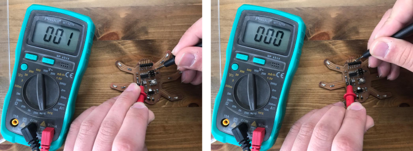
We first checked for continuity between the ATtiny44’s GND pins, the SPI header, and the FTDI header. The digital multimeter ought to beep and display a reading of about 0 Ohm. This implies that each of the three pins is linked.
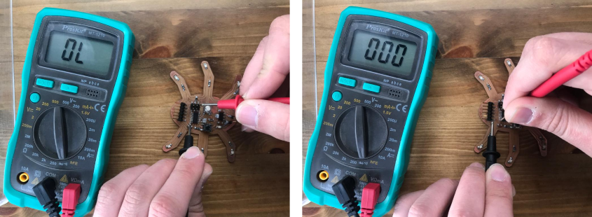
Next, we checked the continuity between the ATtiny44’s VCC pins, the SPI header, and the FTDI header. The digital multimeter ought to beep and display a reading of about 0 Ohm. This implies that each of the three pins is linked.
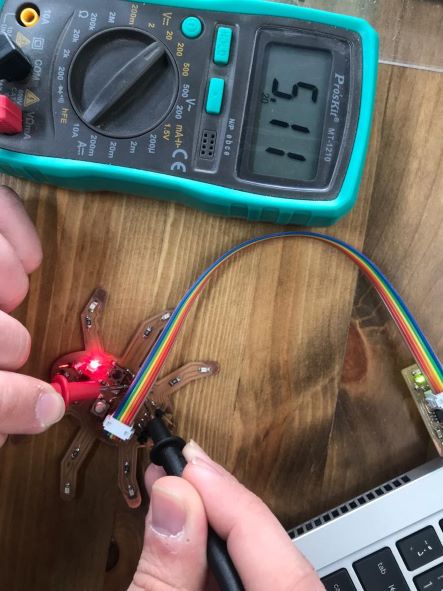
The board was then linked to USB, followed by the FabTiny programmer. We took a reading of the voltage between the GND and VCC pins. The digital multimeter displayed 5V, the voltage of a USB port.
Testing using an Oscilloscope
What is an Oscilloscope?
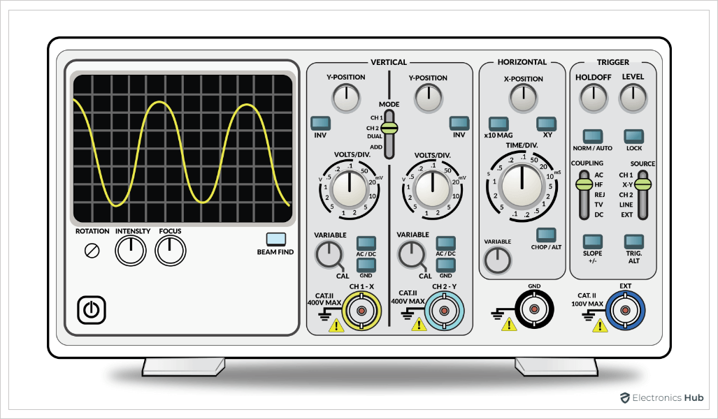
Per TechTarget Network, “an oscilloscope is a laboratory instrument commonly used to display and analyze the waveform of electronic signals. In effect, the device draws a graph of the instantaneous signal voltage as a function of time.
A typical oscilloscope can display alternating current (AC) or pulsating direct current (DC) waveforms having a frequency as low as approximately 1 hertz (Hz) or as high as several megahertz (MHz). High-end oscilloscopes can display signals having frequencies up to several hundred gigahertz (Ghz). The display is broken up into so-called horizontal divisions (hor div) and vertical divisions (vert div). Time is displayed from left to right on the horizontal scale. Instantaneous voltage appears on the vertical scale, with positive values going upward and negative values going downward.”
Testing
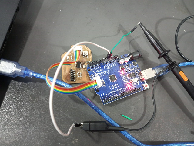
We used Suha’s board to read the power input using the oscilloscope. So, what we is done is that the probe’s positive wire is connected to the Arduino board’s 5 volt pin (otherwise, you can also connect it to the board’s VCC pin) while the probe’s negative wire is connected to the Arduino board’s ground (another option is to connect it to our board’s ground).
The board is powered by an Arduino, so the input voltage is 5V.
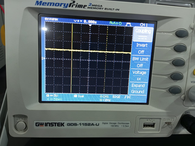
Results
To display the result, we used a block division of 5. So, as expected, the oscilloscope displayed the signal to be one block above the x -axis (I.e. +5V). Obviously, there reading is a bit noisy and there are fluctuations in the readings. A possible solution to this is adding a capacitor which will stabilize the input voltage.
Oscilloscope Trigger
The oscilloscope trigger function makes it possible to display repeating waveforms on the screen steadily. The trigger allows the time base to begin its scan at the same spot each time the waveform is repeated.
The oscilloscope trigger makes it possible to observe waveforms in this fashion. Without it, the time base would start at a random place on the waveform each time it was repeated, rendering the waveform image meaningless.
In order to read the signal more easily, we use the trigger feature on the oscilloscope. Triggering comes in a variety of forms, including:
- Edge trigger (rising and falling edge)
- Pulse trigger
- slop trigger
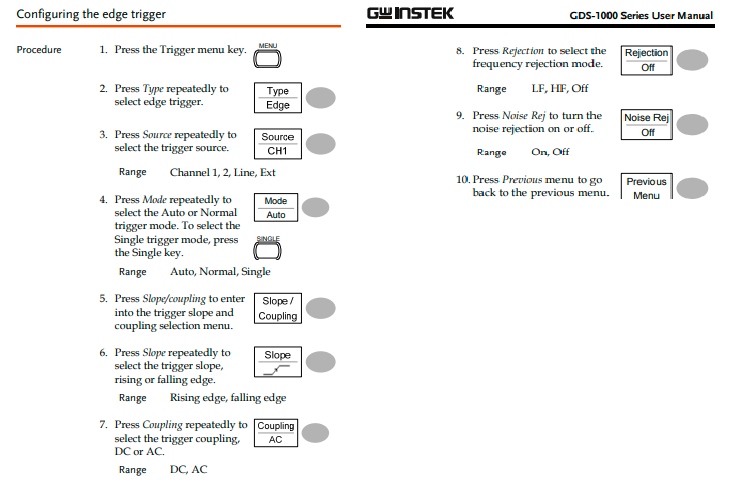
How to use the edge trigger?
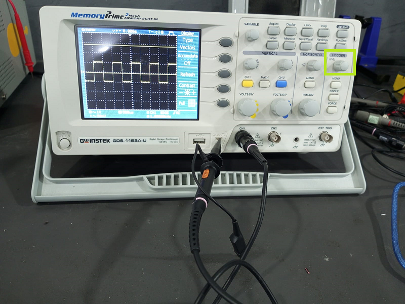
To understand this fully, it’s better to refer to this document, but the below screen shots summarize the process:
You attach the probe to the oscilloscope as shown in the above image, then you click on single, which is underneath the trigger knob. This is the signal that results from the probe’s test. The wave will stope as a result.
Individual Assignment
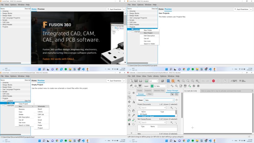
I used AutoDesk Eagle to design the board.

After downloading the software, the first step is to create a new project. Then, you should create a new schematic, which will include the components of your PCB.
In this assignment, I decided to replicate the hello world board with ATtiny 45.
The board includes the following components:
- ATtiny 45
- FTDI
- ISP
- 10k Ω resistor
- 1k Ω resistor
- 2 x 500 Ω resistor
- 1 uF capacitor
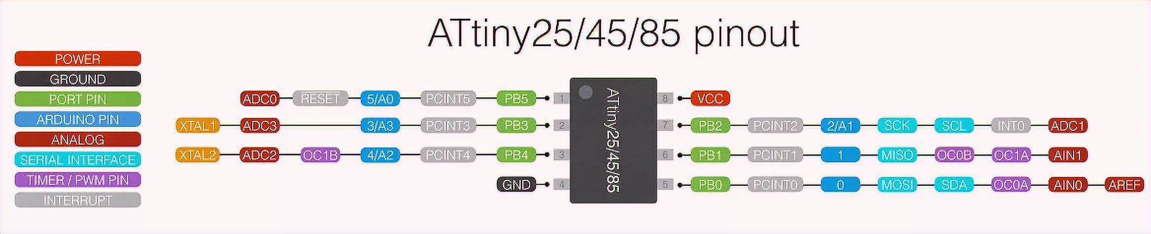
Before going further, it is important to know the pinout of the IC. This is very important because it helps you connect your components correctly.
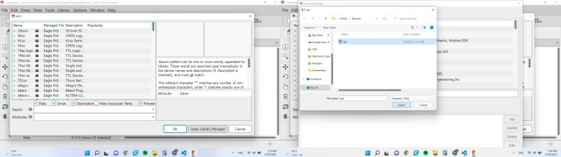
Now, it’s time to add a new component. In order to find the components we have at the lab you should download the fab library.
I decided to not only add a push button and an LED. I also added 3 pin headers that will help me connect a servo or a sensor in future
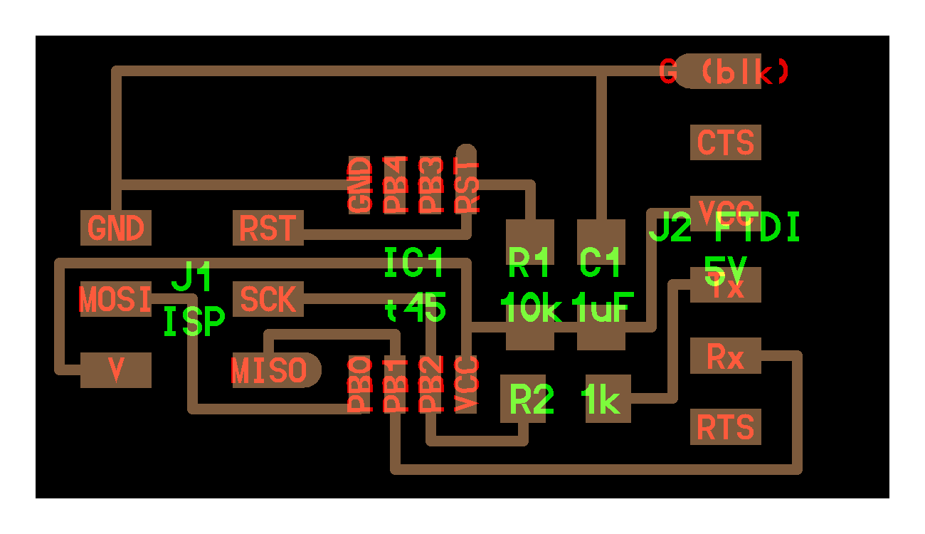
After adding the required components, it is time to connect them to look as follows
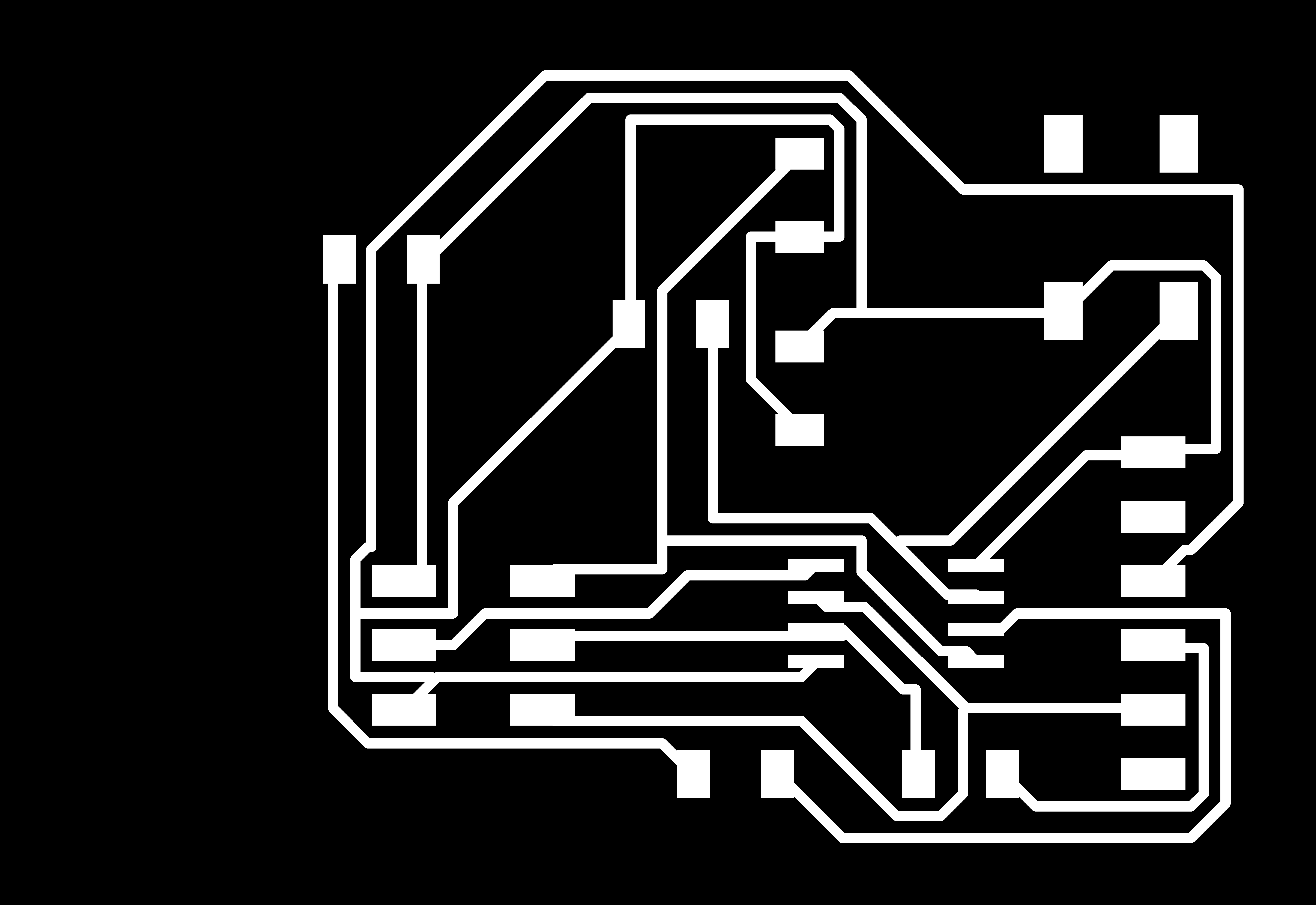
Now, you should move to the board to layout the components.
In order to trace the components, one should go to AutoRoute and choose the number of sides the board will have. For me, it is only one. This will most probably not work so you need to either connect the components manually or move them and autoroute until it works.
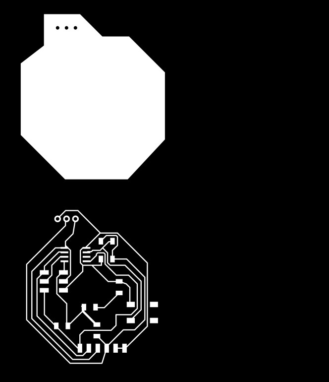
Afterwards, I changed that outer outline so the board looked as follows:
CAM
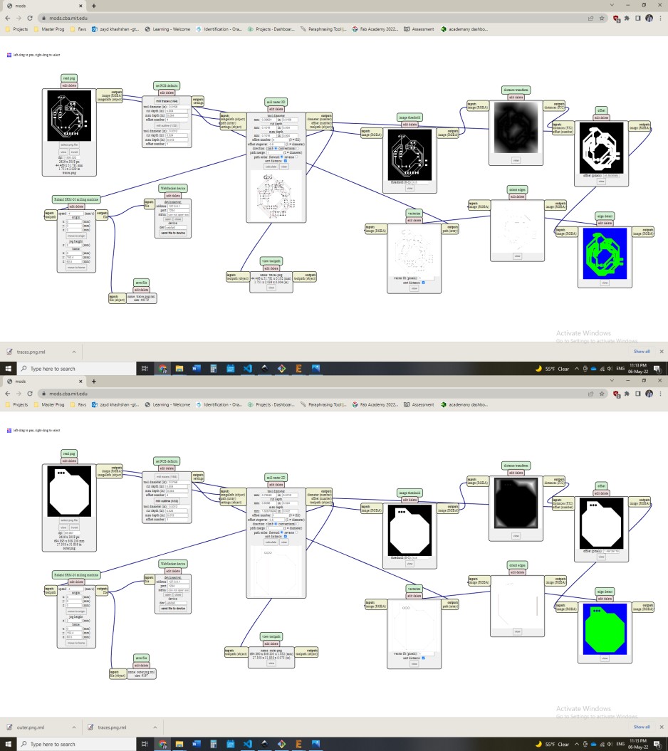
Before going to FabModules, you should export the traces and cut images.
Then, in FabModules, the settings are altered to as outlined in the Electronics Production section which resulted in the below:
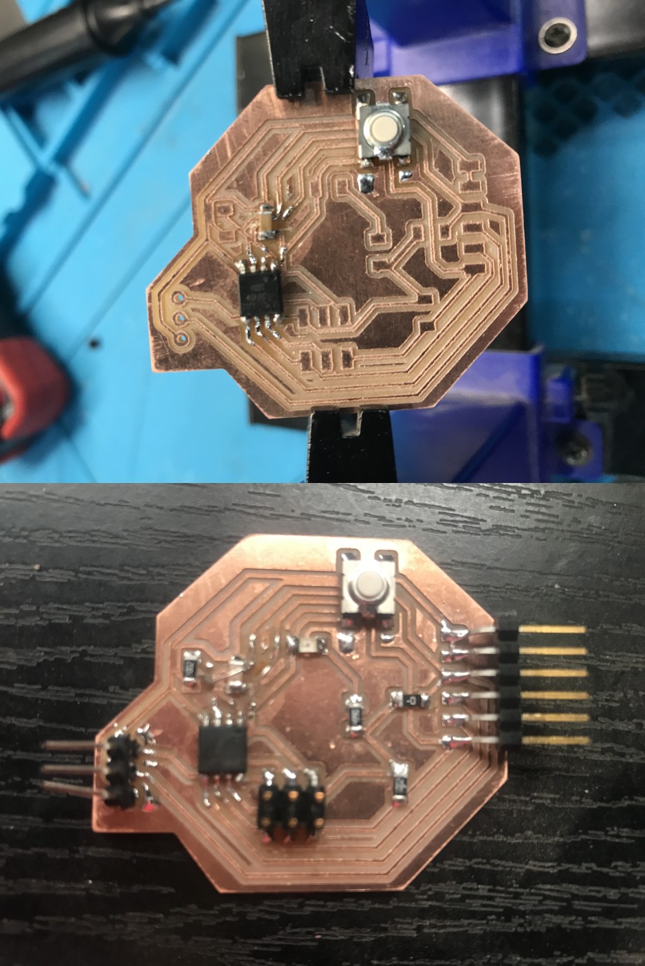
Soldering
Now, it is time to solder the components, I faced a problem that some traces came out, and I solved it by using external connectors.
Programming
I uploaded the following code to test the board:
int buttonPin = 0;     // the number of the pushbutton pin
int ledPin1 =  4;      // the number of the LED pin
int ledPin2 =  1;      // the number of the LED pin

void setup() {
pinMode(ledPin, OUTPUT);

pinMode(buttonPin, INPUT); // initialize the pushbutton pin as an input:
}

// the loop function runs over and over again forever
void loop() {
   buttonState = digitalRead(buttonPin);

  // check if the pushbutton is pressed. If it is, the buttonState is HIGH:
  if (buttonState == HIGH) {
    // turn LED on:
    digitalWrite(ledPin1, LOW);
    digitalWrite(ledPin2, LOW);
  } else {
    // turn LED off:
    digitalWrite(ledPin1, HIGH);
    digitalWrite(ledPin2, HIGH);
}
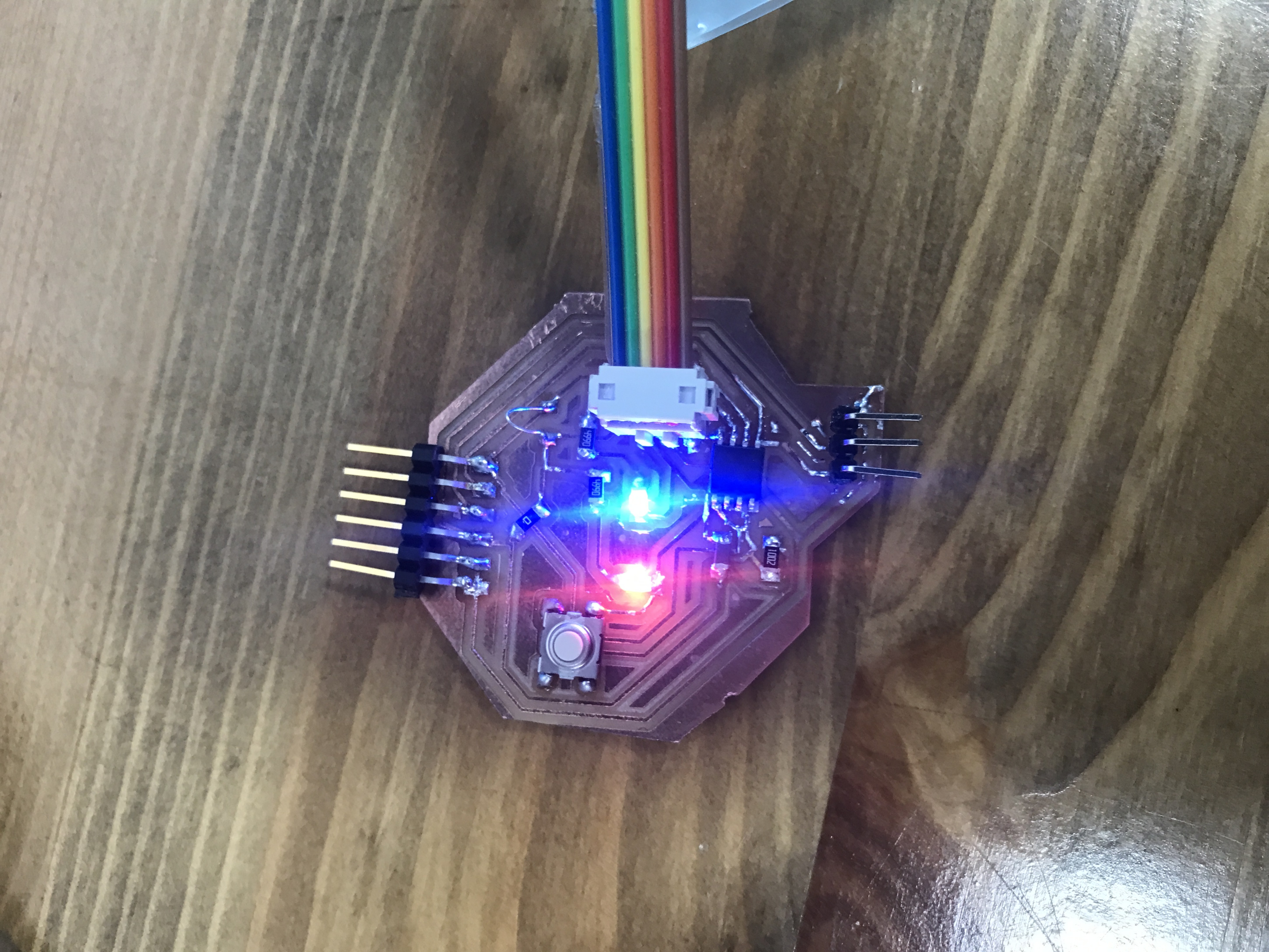
Hero Shot
After uploading the code, here’s how the board looked: