3. Computer Aided design
This week I used Fusion 360 to model the first conceptual design of my final project, a multi-purpose robotic arm - customized for people with ALS. Moreover, I designed my personal coin using Inkscape.
3D Modelling
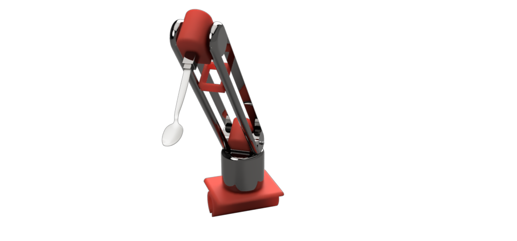
Using Fusion 360, I modelled the first conceptual design of a 3 DoF multi-purpose robotic arm.
Why Fusion 360?
I like Fusion 360 because it is user-friendly, and can do almost everything related to computer-aided design. In fact, in addition to 2D & 3D modelling, you can do finite element analysis to check whether your model meets design strength requirements. Based on the results, you can optimize the model in the generative design workspace. Moreover, in Fusion 360, you may generate G-code to manufacture your model.
Another cool thing about Fusion 360 is that it has good rendering and animating workspaces, which I used to render the above picture and animate the model at the top of the page, respectively.
Design
This section discusses the details of my design.
Inspiration
Teaching digital fabrication, I noticed that one of the best students, diagnosed with ALS, was not comfortable dealing with CAD software. She also faced great difficulties doing important and daily tasks such as eating. Therefore, I feel it’s my responsibility to build something that may make her life easier, and help her fulfil her potential.
“Amyotrophic lateral sclerosis , or ALS, is a progressive nervous system disease that affects nerve cells in the brain and spinal cord, causing loss of muscle control” [1]
Components
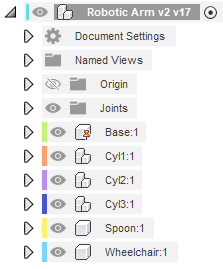
I used six main components in this project. The first one is the base, which will be attached to the wheelchair handle. Furthermore, three of the modelled components (Cyl, Cyl2, & Cyl3) allow for the robotic arm to have 3 DoF. The final two components are the wheelchair and a spoon, which is one of the end effectors the robotic arm may have. I have not designed the end effector engagement and disengagement mechanism yet, but this is the next step.
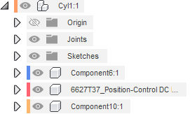
Some components consist of several sub-components too. An example is Cyl1, which include a step motor and two other components. It is important to design around electronic parts that are available in the market, and that is where a Fusion 360 tool called “Insert McMaster-Carr Component” comes in handy. I used this tool to install all stepper motors I used in the design.
Base Design
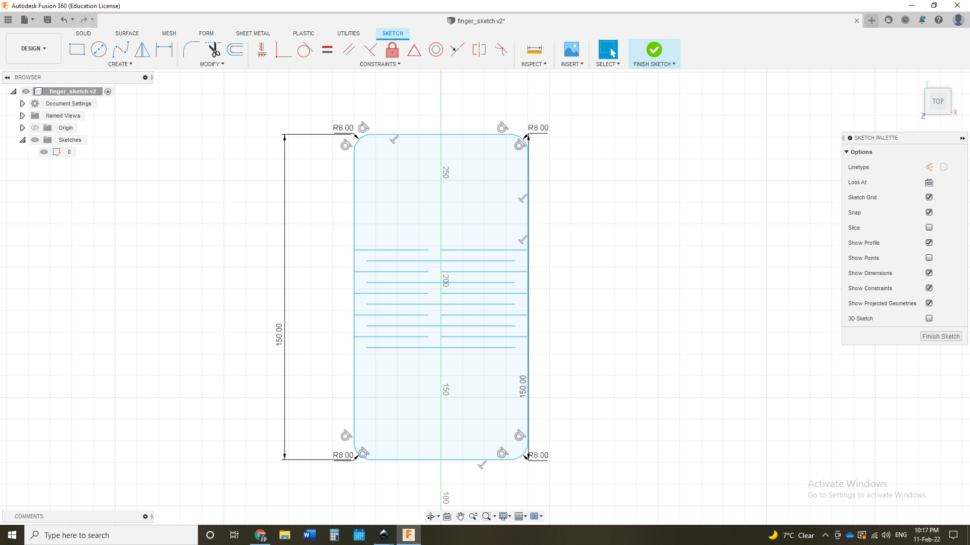
For demonstration purposes, I will guide you through the process of designing the base, which starts with a 2D sketch, as illustrated below.
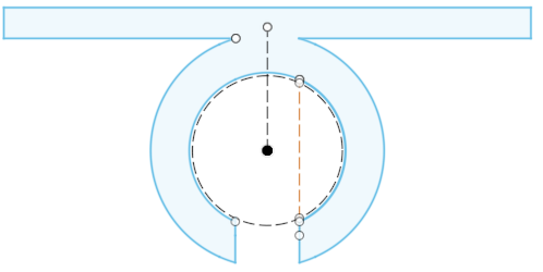
I first defined a construction circle, with a diameter equal to the diameter of the chair handle. Afterwards, using the offset feature, I drew three more circles that define some features in the base component. Then, I quit the 2D working space to extrude the sketch, as shown below
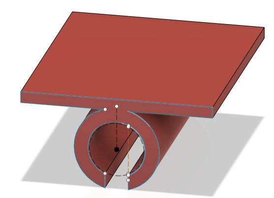
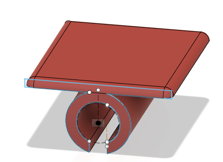
Then, the corners are filleted in order to reduce their deformation, when the part is manufactured.
Design Steps
You may watch how the design is made below:
3D Model
2D Modelling
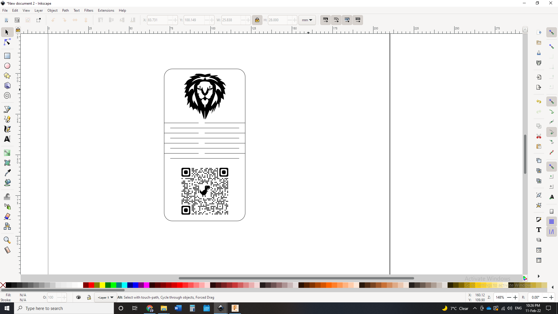
Using Inkscape, I modelled my personal coin.

Why Inkscape?
Inkscape is a free and open source vector graphics editor for GNU/Linux, Windows and MacOS X. It offers a rich set of features and is widely used for both artistic and technical illustrations such as cartoons, clip art, logos, typography, diagramming and flowcharting.[2]
Design
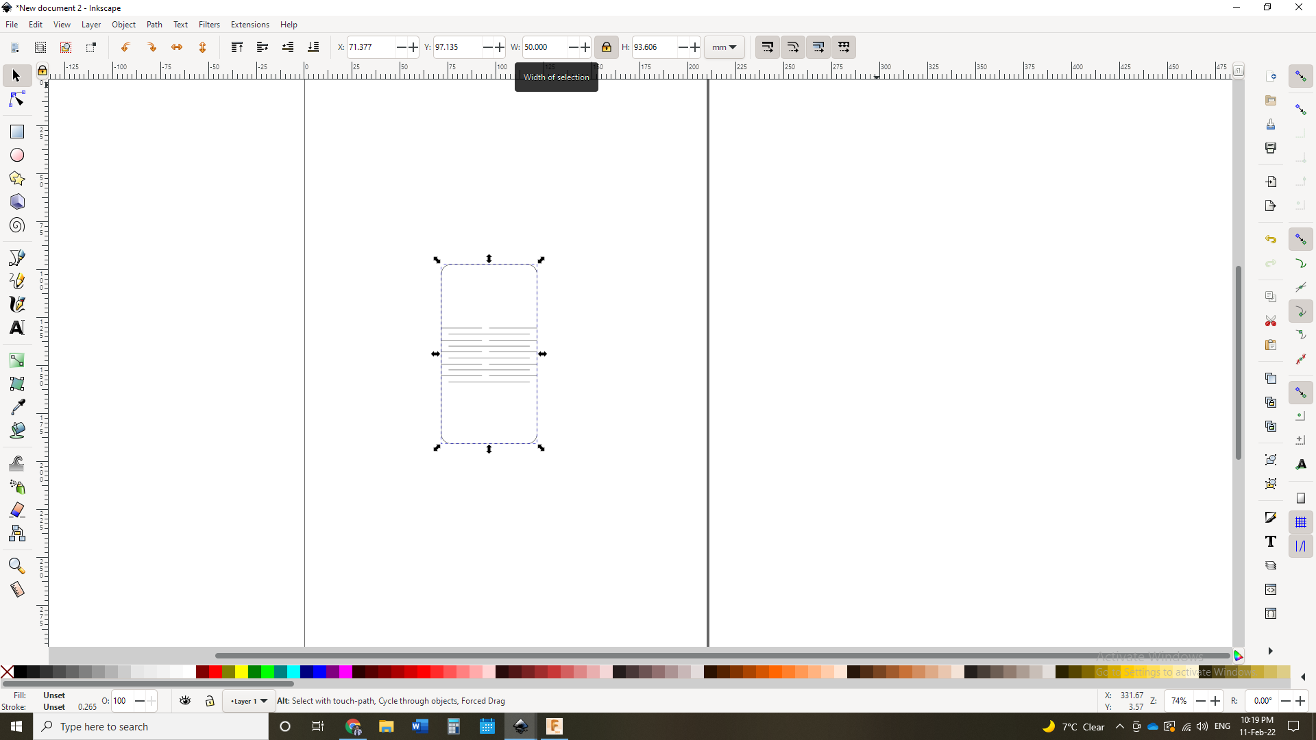
The design features three main aspects: 2D vector drawing, a living hinge, and rasters. I first drew the 2D design in Fusion 360 because its user interface is much easier.
Then, I imported the file to Inkscape, and changed its dimensions.
After that, I imported a QR code, which I used Google Chrome to generate, linking to my LinkedIn account. The QR code is then placed in the coin.
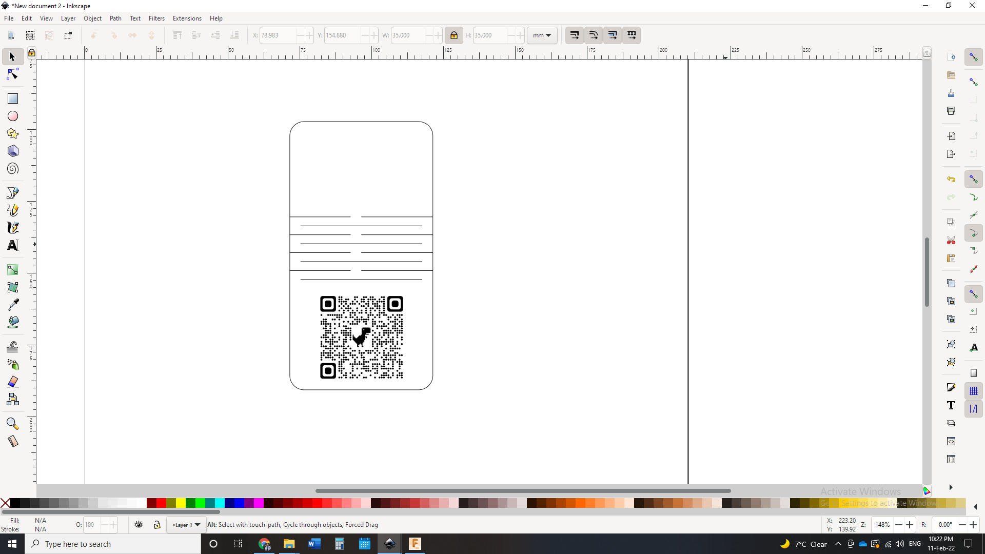
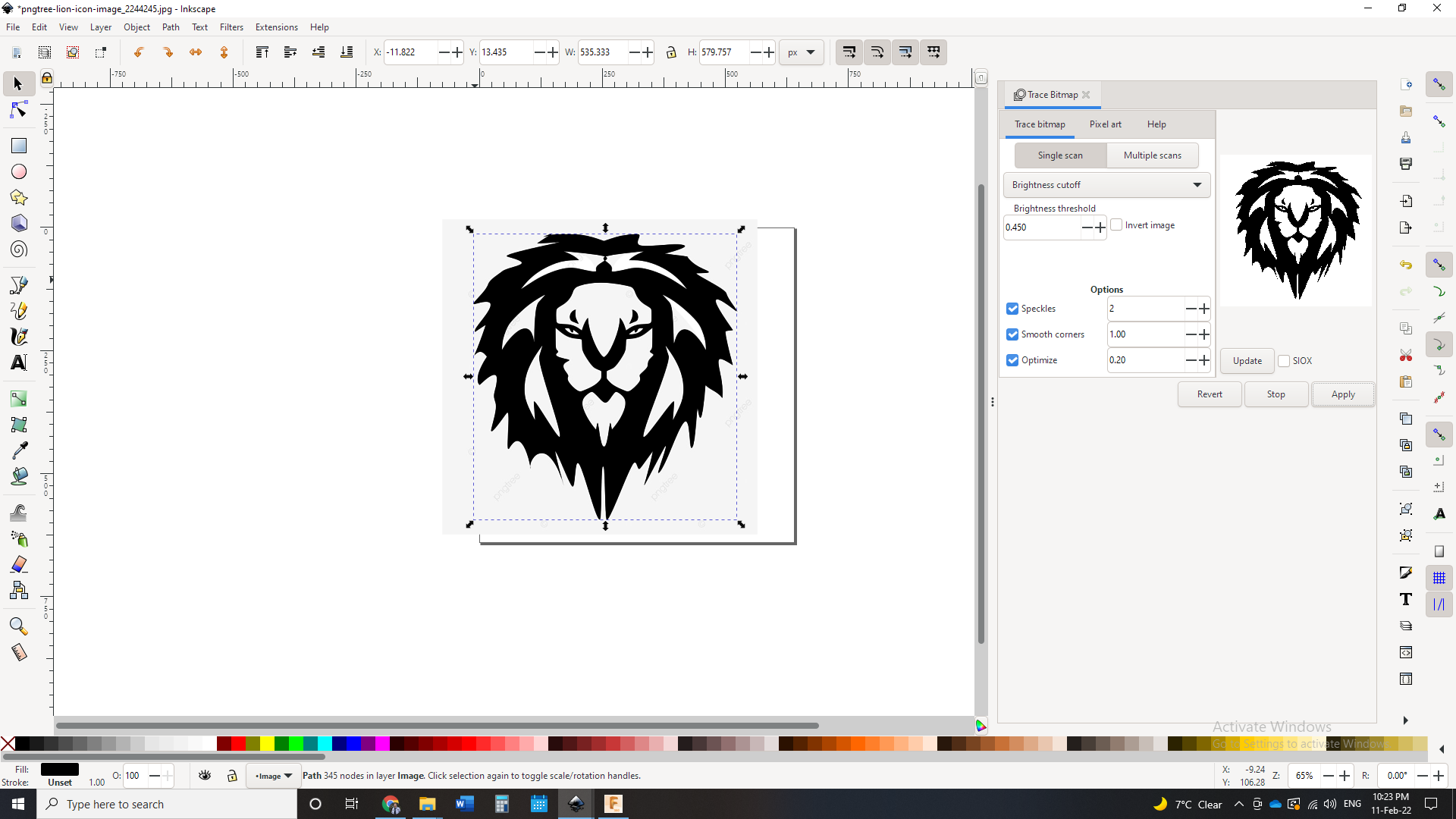
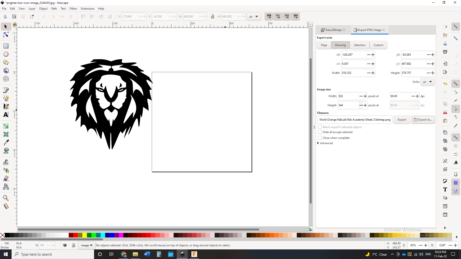
For the final feature, which is the lion icon, I first downloaded an image from Google. Then, I imported it to Inkscape and removed its background using the trace bitmap command. Finally, I resized it and positioned it in the top of the coin.
Gimp
Now it’s time to use a raster graphics software. Gimp is “a cross-platform image editor available for GNU/Linux, macOS, Windows and more operating systems. It is free software, you can change its source code and distribute your changes.”
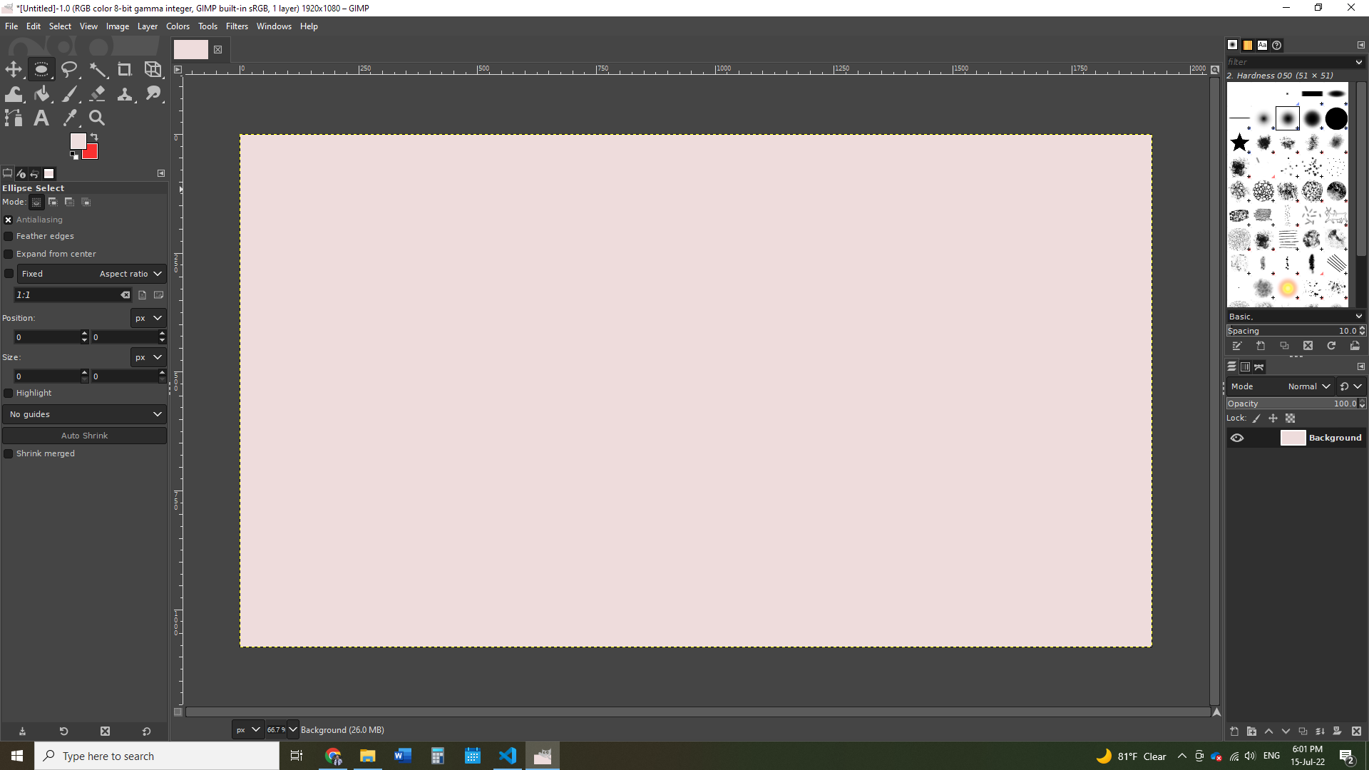
I wanted to do a random design to figure out the difference between raster and vector graphics so I did the below:
- I started by opening a new sheet:
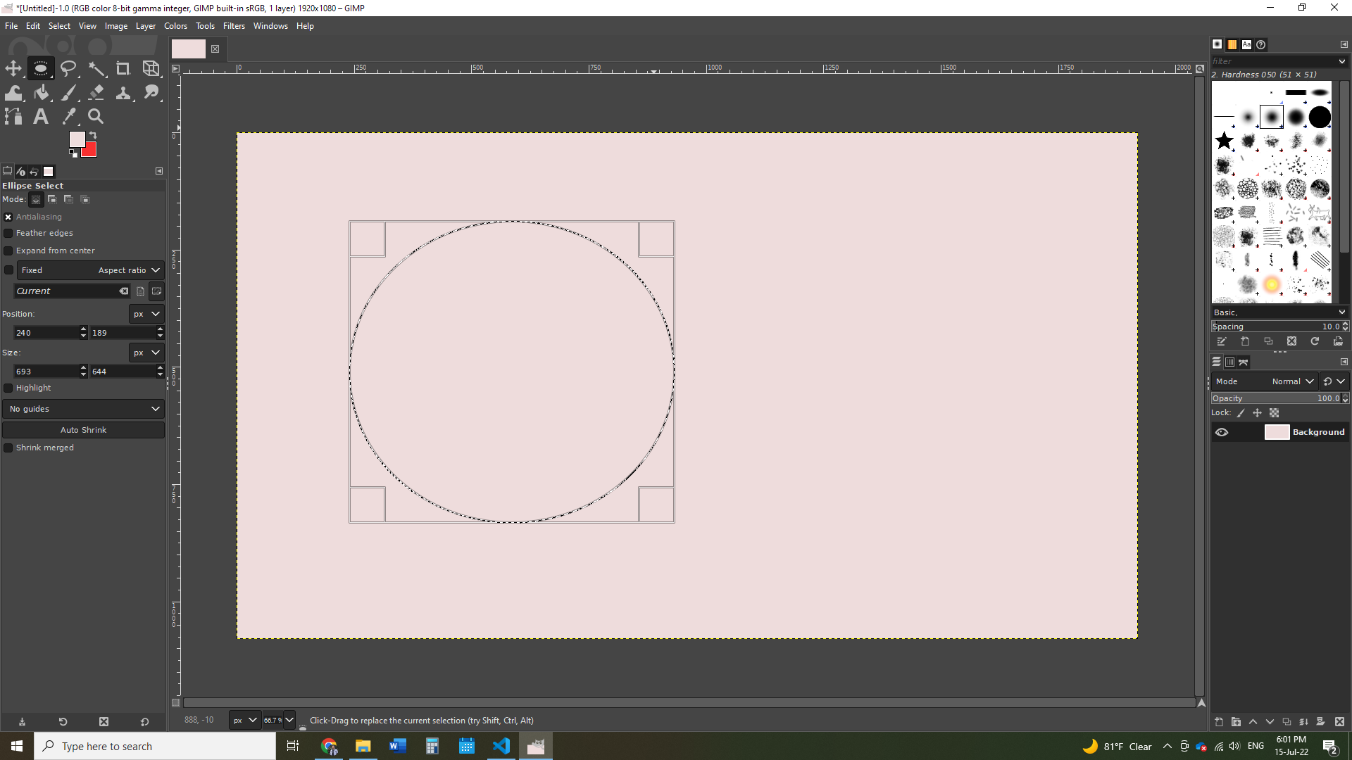
- Then I used the Ellipse Select tool to draw an ellipse

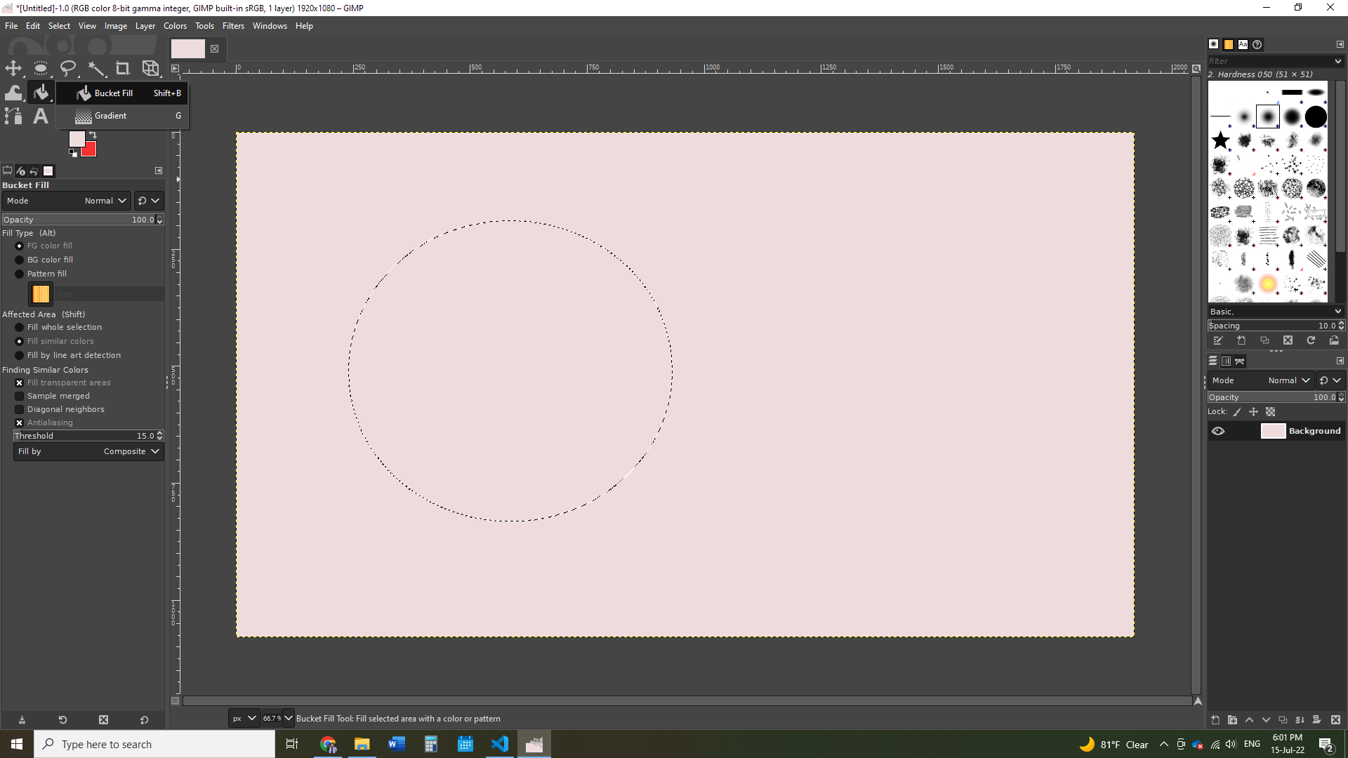
- Then, I used the Gradient fill tool to color the ellipse. I also chose the coloring to be a gradient between red and purple.
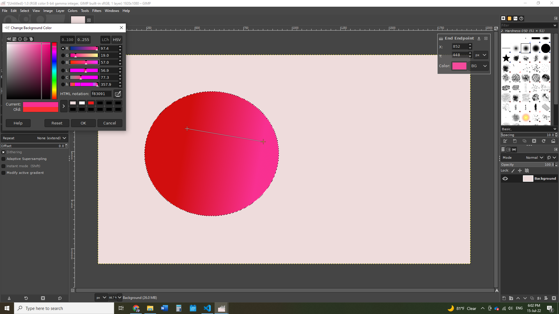
- After that, I added text using the Text tool.
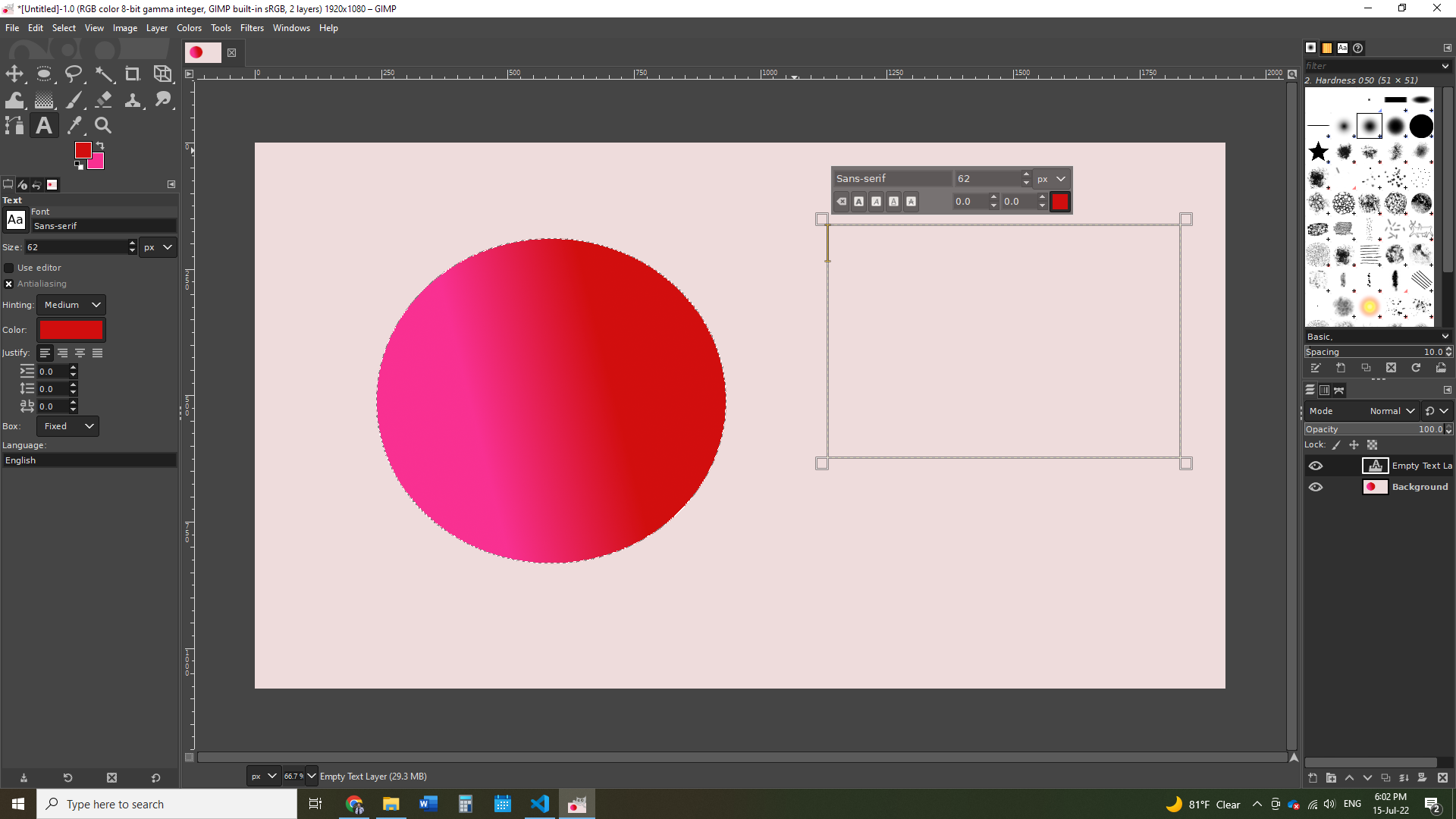
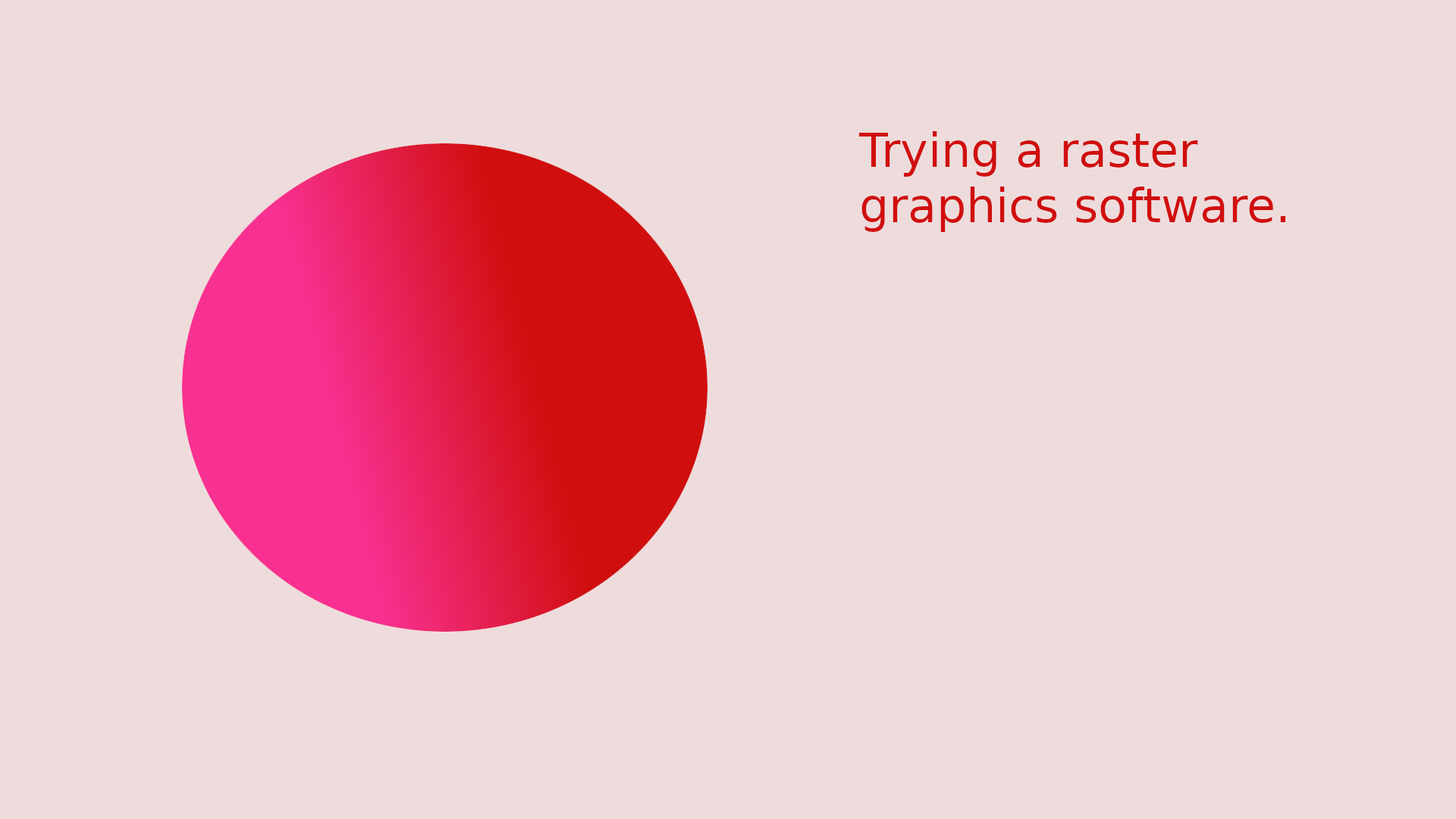
- The final result looked as follows:
Raster vs Vector
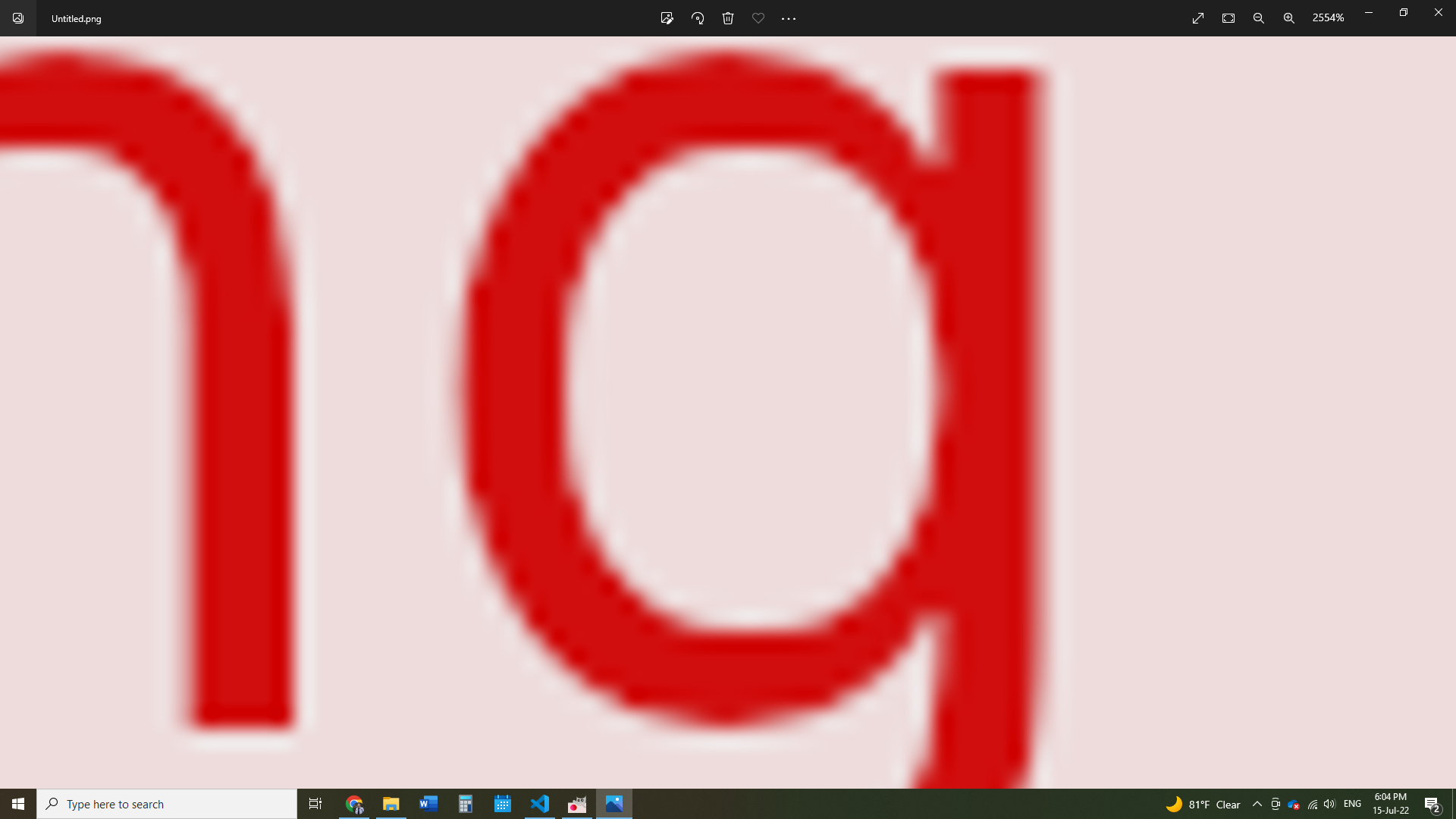
Per GeeksForGeeks, “The main difference between vector and raster graphics is that raster graphics are composed of pixels, while vector graphics are composed of paths. A raster graphic, such as a gif or jpeg, is an array of pixels of various colors, which together form an image.”
In order to easily differentiate between rasters and vectors, simply zoom in, and if the quality changes then this is a raster (as shown below from the drawing I made in Gimp):
Files
- 2D Coin: SVG, PNG
- Robotic Arm: Fusion 360, STL