12. Output devices
This week I worked with output devices like motors. I plan to use the board I make for this assignment in my final project.
Group Assignment
This week’s group assignment is to measure the power consumption of an output device. So, we decided to do this on a DC motor.
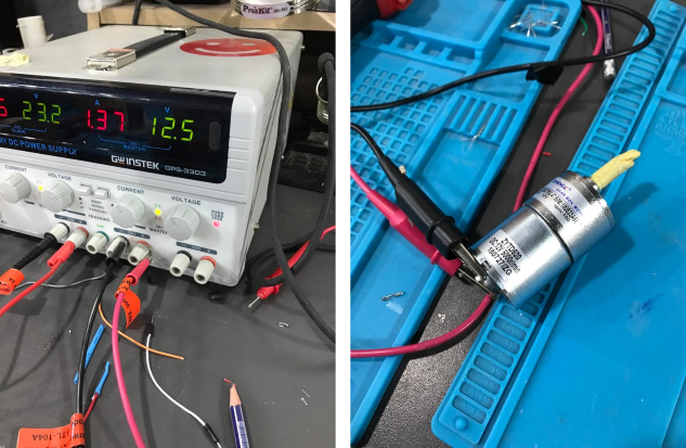
It is important to remember that Power = Voltage * Current. So, what we need to do is basically measure the current and voltage of the DC motor using a multimeter. Before that it is essential to note that:
- For voltage measurement, the multimeter needs to be connected in parallel with the motor.
- For current measurement, the multimeter needs to be connected in series with the motor.
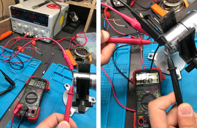
So, after using the values shown in the above picture, Power = 1.16 Watt.
Individual Assignment
In the final project, I need to connect 4 servo motors that will actuate 4 fingers of the gripper and a stepper motor to lift the gripper. So, in this board I will connect them all. I chose the stepper motor because I need continuous rotation and high holding torque.
Design
Schematic
I started with the schematic, where I connected all components. As I need a lot of pins, I used ATmega328P microcontroller. An advantage of this is being able to use Arduino libraries. It is worth noting that my friend Aybak helped me a lot in the schematic. He helped me understand multiple concepts including the need for a high resistor to connected with the reset.
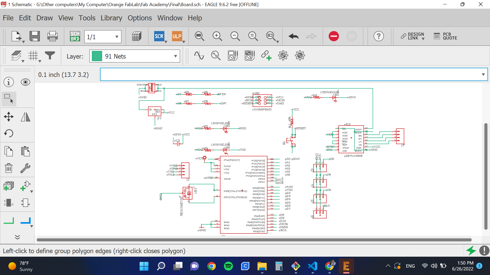
Main Features
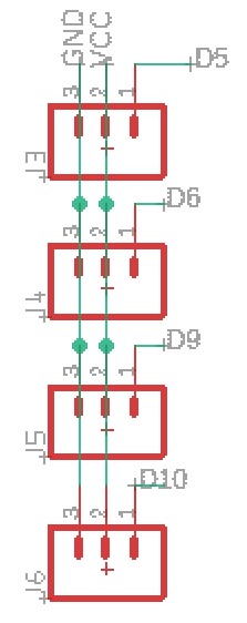
- To connect servos, I used a 3x1 pin header. 2 pins are connected to VCC and ground, respectively, while the third is connected to a signal.
- In order to work with a stepper I made place for its A4998 driver.
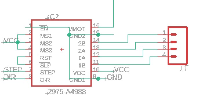
- When I tried to wire everything together, I had some difficult time connecting all signals. So, I used zero ohm resistors to fix the problem.

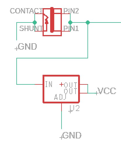
- The stepper motor requires 12V, but other motors and components cannot stand this high voltage. So I used a 12V power supply as the main source of power for the circuit and connected this to the stepper. But, I added a voltage regulator to power other components.
- I added a place for a bluetooth chip to be connected.
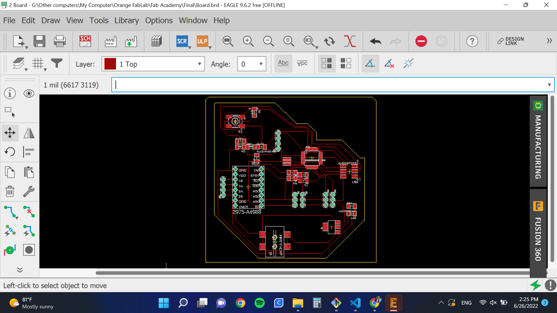
Layout
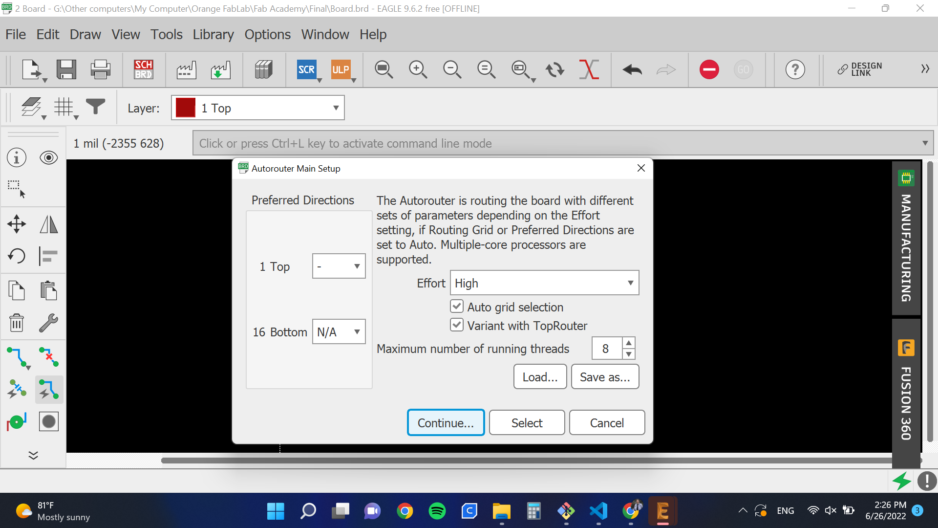
To connect signals, I used Autorouter. But it couldn’t connect everything so I used some zero ohm resistors.
I also edited the outer boundary to look as follows:
Milling
CAM
I exported the 2 images, one for the traces and one for the the outline as below. Also, note that I edited the inside colors for the outline picture because Fab Mods needs a difference in colors to detect where to cut.
Then, I transported this to Fab Mods to get the RML files.
Soldering
Then, I soldered the board.
Programming
I wanted to control all motors using serial communication and based on received data. So I uploaded the following code.
#include <Servo.h>
int x;
const int dirPin = 8;
const int stepPin = 7;
const int stepsPerRevolution = 200;

Servo myservo1;
Servo myservo2;
Servo myservo3;
Servo myservo4;

void setup() {
  myservo1.attach(5);
  myservo2.attach(6);
  myservo3.attach(9);
  myservo4.attach(10);


  pinMode(stepPin, OUTPUT);
  pinMode(dirPin, OUTPUT);
  Serial.begin(9600);
  Serial.setTimeout(1);
}

void loop() {
  while (!Serial.available());
  x = Serial.readString().toInt();
  if (x) {
    if (x == 1) {
      myservo1.write(0);
      myservo2.write(0);
      myservo3.write(0);
      myservo4.write(0);
    }
    if (x == 2) {
      myservo1.write(180);
      myservo2.write(180);
      myservo3.write(180);
      myservo4.write(180);
    }
    if (x == 3) {

        digitalWrite(dirPin, HIGH);
        // digitalWrite(dirPin, HIGH);
        digitalWrite(stepPin, HIGH);
        delayMicroseconds(1000);
        digitalWrite(stepPin, LOW);
        delayMicroseconds(100);
    }

    if (x == 4) {

        digitalWrite(dirPin, LOW);
        digitalWrite(stepPin, HIGH);
        delayMicroseconds(1000);
        digitalWrite(stepPin, LOW);
        delayMicroseconds(100);

    }


  }

}
I used computer vision to actuate the motors. The reason behind using serial communication is because the computer vision code is in Python, and it uses serial communication to actuate the motors. For more information about the system, please check my Interface and Application Programming assignment.