14. Networking and communications
This week I worked on controlling the board I designed in Output Devices via Bluetooth
Group Assignment
The following information is extracted from this website
Chip to Chip Communication Protocols Overview The majority of PCBs have numerous ICs, which are required for the boards to communicate with one another and are typically used for data transfer across many PCBs by users. The most popular protocols in these connections are SPI, I2C, and UART. Here, some of the key features of these protocols are discussed, along with some design ideas for assuring high-fidelity communication.
SPI (Serial Peripheral Interface):
SPI is a synchronous duplex communication protocol, allowing for simultaneous data transmission and reception. Master Out Slave In (MOSI), Master In Slave Out (MISO), Serial Clock (SCLK), and Chip Select are the commonly used four wires (CS). In the diagram below, a typical SPI communication is depicted.
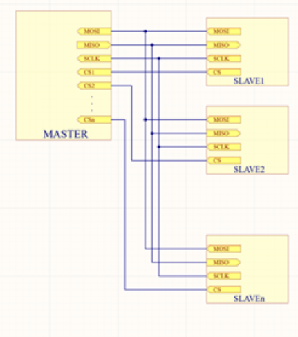
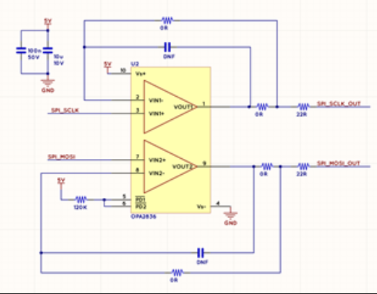
One master can talk to many slaves, but each slave requires a chip select signal. This means that for every n slaves, the master will require n+3 pins. SPI can communicate at up to 100MHz of speed. However, in order to communicate fast, various additional circuits can be needed. The most frequent problems with high speed SPI signals are overshoot and ringing. This problem can be readily fixed by incorporating a small series resistance into the signal route. If the communication distance is significant, it is recommended to buffer the output and clock lines. A sample buffer circuit is shown below: N is represented in the picture below.
Inter-Integrated Circuit, or I2C
I2C is a widely used protocol for inter-IC communication. A data line (SDA) and a clock line are used for communication (SCL). Any number of slaves can be connected to a single master as long as the input capacitance of the bus is less than the I2C standard’s maximum. Speeds of up to 5MHz are supported.
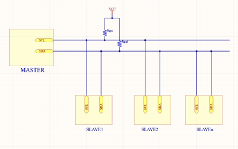
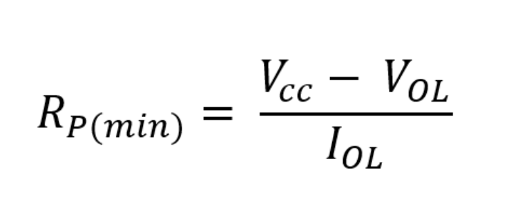
An open-drain communication standard necessitates the use of a pull-up resistor. This allows ICs with different supply voltages to connect to the same bus. Value of the pull resistor is a crucial design element. If we use a low resistor, the IC won’t be able to pull the line LOW. If the low-level voltage VOL and sink current IOL are as follows, the minimum allowable pull-up resistance is:
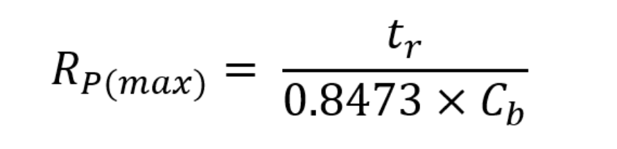
On the other hand, if we select a very high pull-up resistor, it will take a long time to charge the input capacitor. The signal may not therefore reach the logical high before being pushed down. This is especially crucial for high-speed data transfer. If tr is the signal’s rise time and Cb is the bus’s capacitance, then the following formula may be used to calculate the maximum allowable pull-up resistance:
Universal Asynchronous Receiver Transmitter (UART):
Through the UART protocol, two chips are immediately connected. The Tx of one chip is connected to the Rx of another, and vice versa. Only two chips can communicate with one another over a single UART line because this protocol is not scalable. The block diagram for UART communication is as follows:
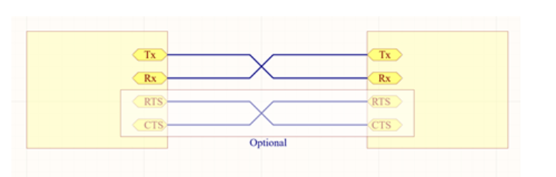
The receiving chip must be informed of the other chip’s transmission pace because no clock is transmitted. To correct for overshoot and ringing, a series resistor should be added to the UART line, just like with SPI. The signals are single-ended, which makes them more noise-sensitive, especially over long distances. Two additional signals, CTS (Clear to Send) and RTS (Request to Send), are sometimes added to the connection to improve its integrity.
We perform a group assignment where we use potentiometers to adjust led intensity. The led is connected to a slave controller board (Aybak board), and the potentiometer is attached to a master controller board (Amin board)
The potentiometer signal is wired to pin A0 on the master board, the led is wired to pin 5 on the slave board, and the final connections are TX on the master board to RX on the slave board and RX on the master board to TX on the slave board.
Files
HERO Shot
Individual Assignment
I want to control the board I designed in Output Devices in a wireless fashion. This is a crucial part of my final project.
For a start, “Bluetooth is a short-range wireless technology standard that is used for exchanging data between fixed and mobile devices over short distances using UHF radio waves in the ISM bands, from 2.402 GHz to 2.48 GHz, and building personal area networks.” Source
Bluetooth HC-05
I will be using the HC-05 module, and in order to understand it fully, it is best to first refer to its manual.
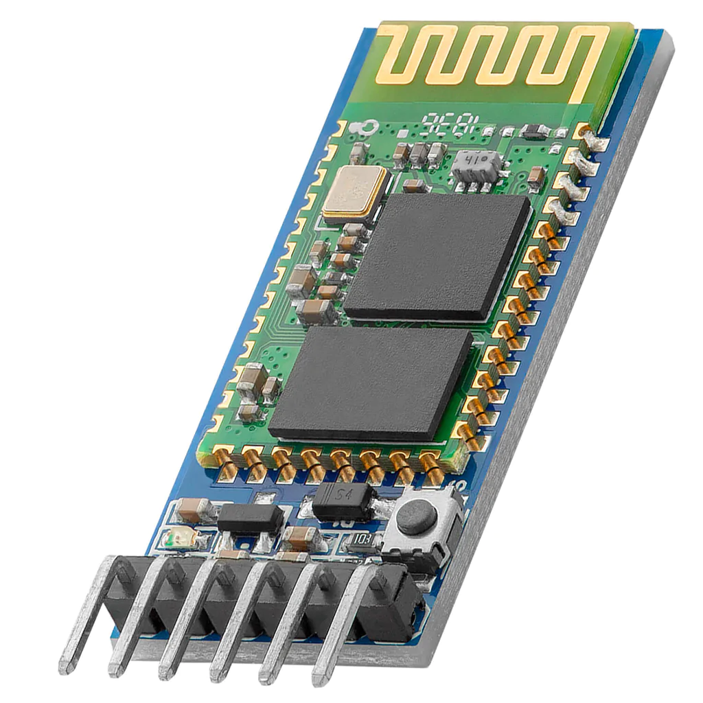
According to the manual, HC-05 has the following pins:
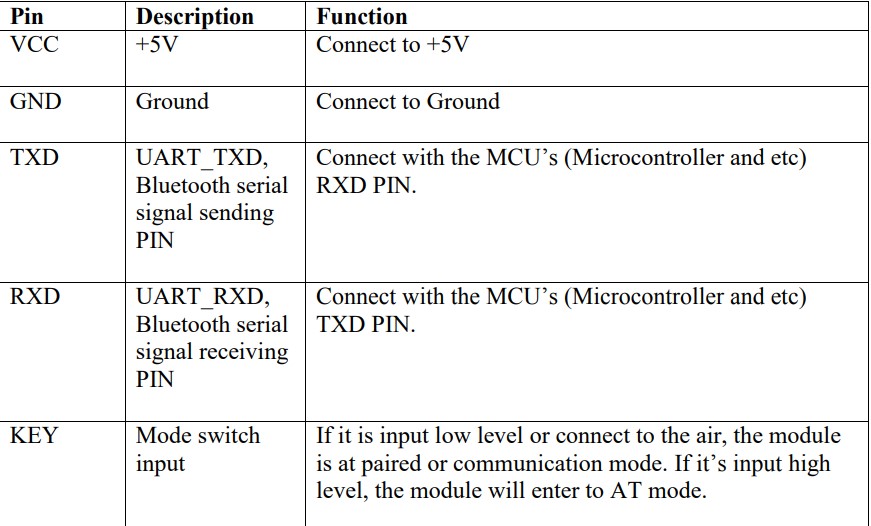
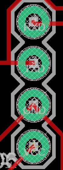
Essentially, to work with this module you need to at least connect 4 pins: GND, VCC, Tx, Rx. I already planned this in my Output Devices, as shown below:
I also connected LEDs to Rx and Tx in order to know when any data is received or sent.
Code
So I basically linked this assignment with the Interface and application programming assignment. The idea is basically to use computer vision (programmed in Python) to do pose estimation of my fingers and then send serial data to the microcontroller, via Bluetooth, to actuate different motors.
So, I used the following Arduino Code:
#include <Servo.h>
int x;

Servo myservo1;
Servo myservo2;
Servo myservo3;
Servo myservo4;

void setup() {
  myservo1.attach(5);
  myservo2.attach(6);
  myservo3.attach(9);
  myservo4.attach(10);
  Serial.begin(9600);
  Serial.setTimeout(1);
}

void loop() {
  while (!Serial.available());
  x = Serial.readString().toInt();
  if (x) {
    if (x == 0) {
      myservo1.write(0);
      myservo2.write(0);
      myservo3.write(0);
      myservo4.write(0);
    }
    if (x == 1) {
      myservo1.write(180);
      myservo2.write(180);
      myservo3.write(180);
      myservo4.write(180);
    }

}
And for the Python code:
cap = cv2.VideoCapture(0)
detector = HandDetector(maxHands = 1, detectionCon = 0.7)
Serial = SerialObject("COM4", 9600, 1)
After that, I started a while loop that reads the input frame from the camera, does pose estimation and finally checks if the index finger is up or down. If it is up, it serially communicates the number “1”. Otherwise, it communicates “0”.
while True:
_, img = cap.read()
img = detector.findHands(img)
LandmarksList, BoundingBox = detector.findPosition(img)
if LandmarksList:
fingers = detector.fingersUp()
if fingers[1] == 1:
Serial.sendData([1])
if fingers[1] == 0:
Serial.sendData([0])
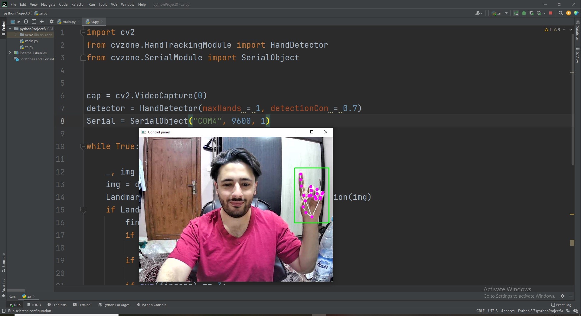
cv2.imshow('Control Panel', img)
cv2.waitKey(1)
Here is how the control panel looks:
HERO Shot
I first tried controlling a servo:
Then, I tried controlling 4 servos, attached to the gripper I’m using in my final project.