Final Project
What Is It?
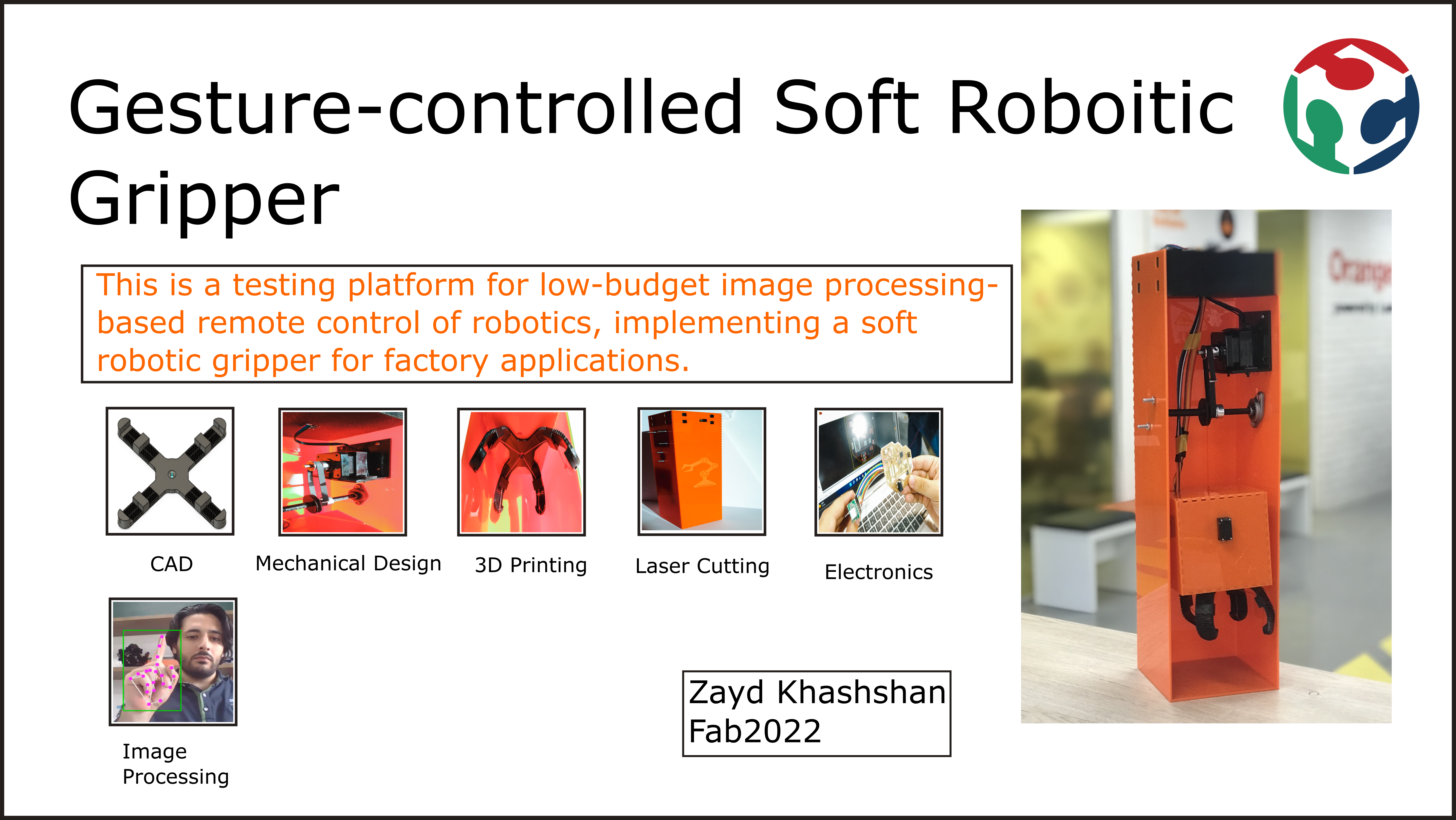
My project is basically a gesture-controlled soft robotic gripper. It is designed to be controlled in a contactless and distant manner via computer vision.
The soft gripper is 3D printed and incorporates the concept of living hinges to make it flexible. Moreover, the fingers are tied by strings. So, when the string is pulled the finger is bent (I.e. when all fingers are bent = gripping position).
The computer vision part does pose estimation of my fingers and detects which fingers are up and which are down. Then, this information is translated into low level control commands for four servo motors that pull down fingers and actuate the gripper.
Bill of Material
| Qty | Description | Price (JOD) | Link |
|---|---|---|---|
| 1 | SMD ATmega328P | 8 | https://mikroelectron.com/Product/ATmega328-TQFP-Made-in-USA/ |
| 5 | SMD resistors | 0.05 | https://mikroelectron.com/Product/1206-SMD-resistor-10K/ |
| 3 | SMD capacitors | 0.05 | https://mikroelectron.com/Product/1206-SMD-Capacitor-16values-20pcs-320pcs-10PF-22UF-Samples-Kit/ |
| 5 | SMD LEDs | 0.05 | Available at lab |
| 1 | Voltage Regulator | 0.6 | https://mikroelectron.com/Product/SMD-Voltage-Regulator-5V-LM1117-5-0-SOT-223-75RC-N06B/ |
| 1 | Power Supply | 5 | https://mikroelectron.com/Product/ADAPTER-12V-2A-POWER-SUPPLY-AC-DC/ |
| 4 | Servo Motor | 7 | https://mikroelectron.com/Product/MG90S-Metal-Gear-Mini-Servo-Motor-180-degree/ |
| 1 | NEMA17 Stepper | 14 | https://mikroelectron.com/Product/Stepper-motor-1-8-per-step-1-7-A-0-36-N-m-NEMA17-17HS4401/ |
| 1 | Stepper Driver | 5 | https://mikroelectron.com/Product/A4988-Stepper-Motor-Driver-Original/ |
| 1 | PLA Spool | 20 | Available at lab |
| 1 | Acrylic | 5 | Available at lab |
Sum = 58.25 JOD
Project Plan
- CAD –> 17 April
- Mechanical Design –> 24 April
- 3D printing –> 1 May
- Laser Cutting –> 8 May
- Electronics Design & Production –> 15 May
- AI Interface System –> 22 May
- Bluetooth Communication –> 29 May
- Documentation, Poster, & Video –> 11 June
CAD & Mechanical Design
I will now go through the parts I designed in this project
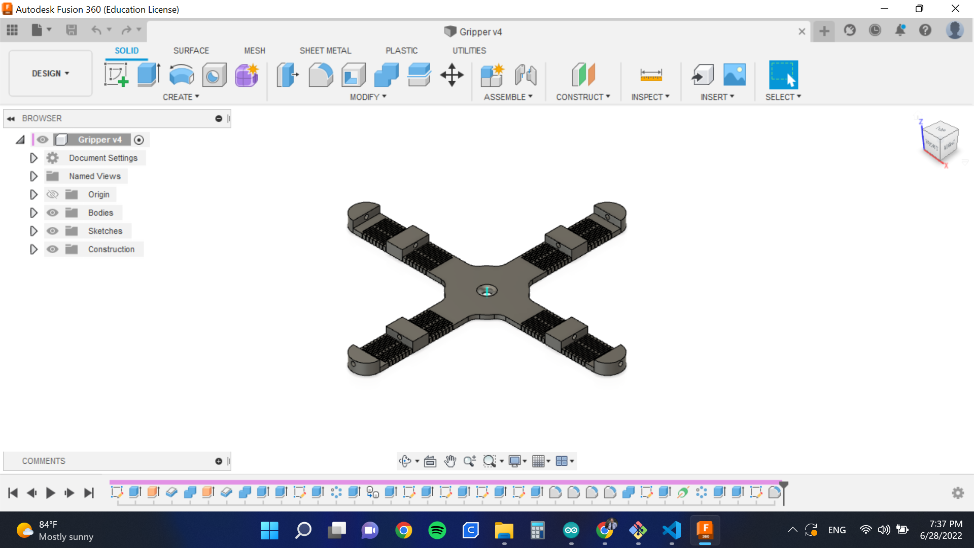
- Gripper: This is a soft 3D-printed gripper. For more information about the design please check my Wild Card assignment.
To download the file, press here
- Gripper Holder: The gripper holder is meant to hold the gripper and 4 servo motors that will actuate the fingers.
To download the file, press here
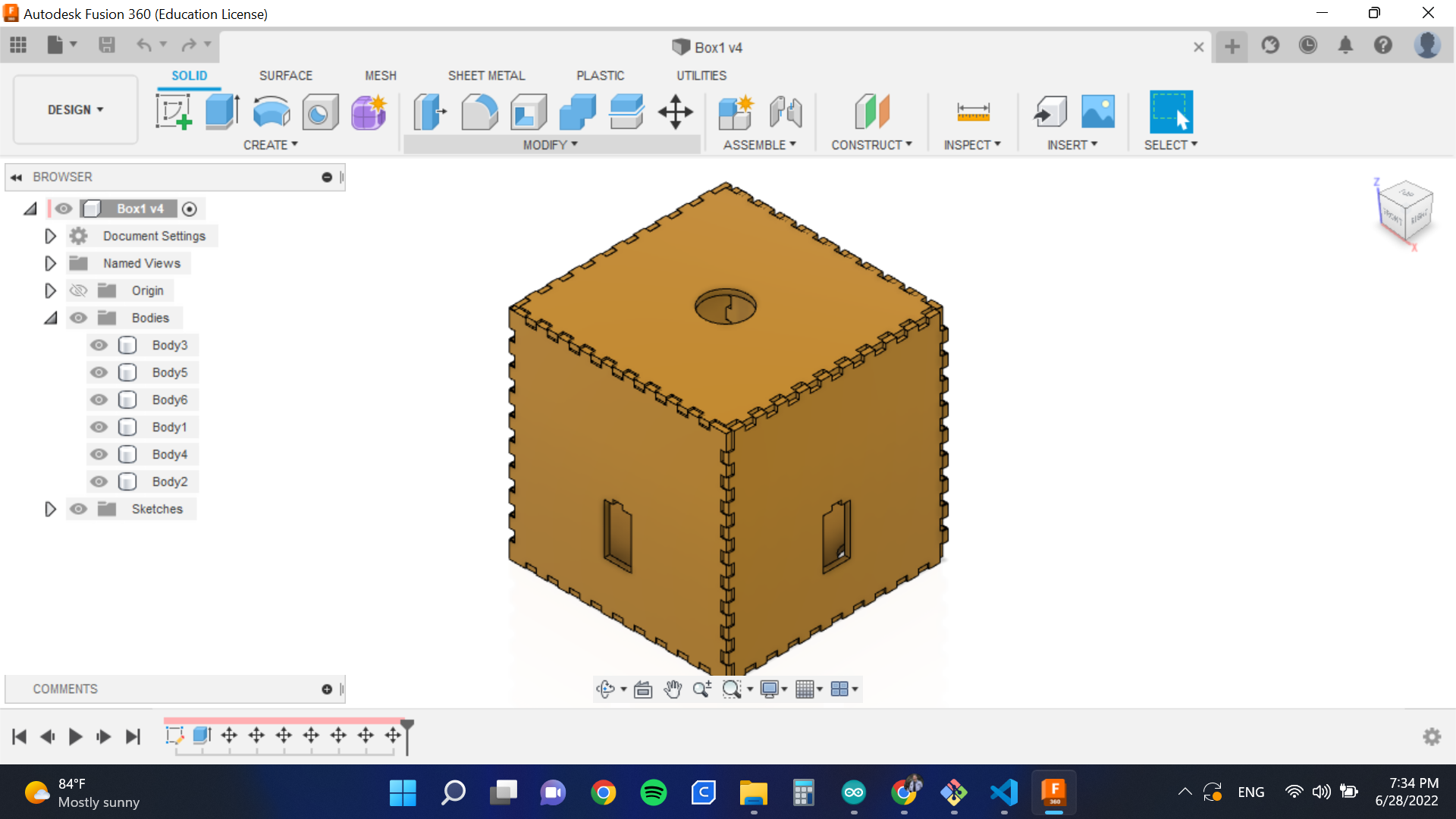
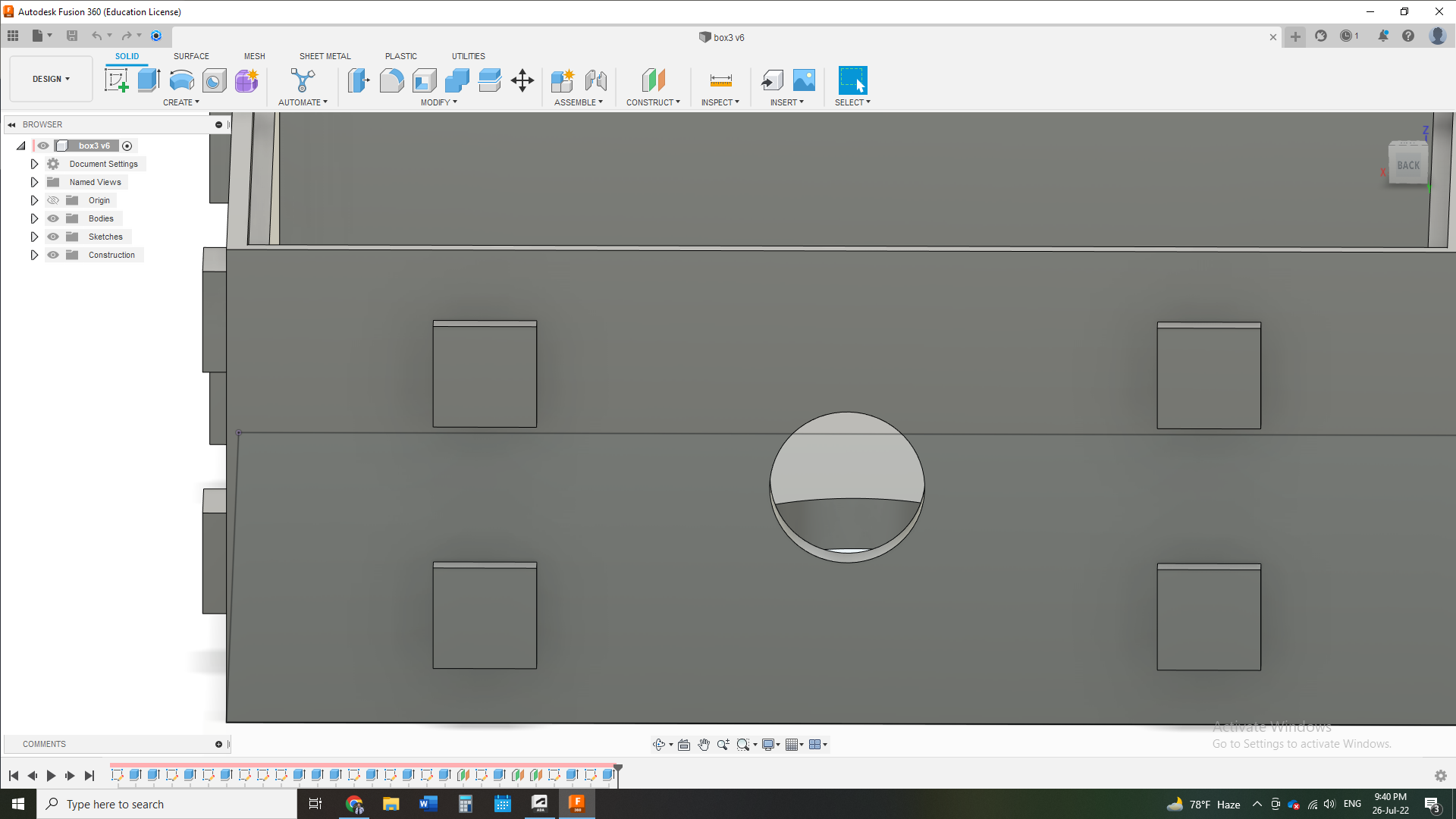
- Outer Case: The outer case is parametrically designed and it is meant to be the outer casing of the project.
To download the file, press here
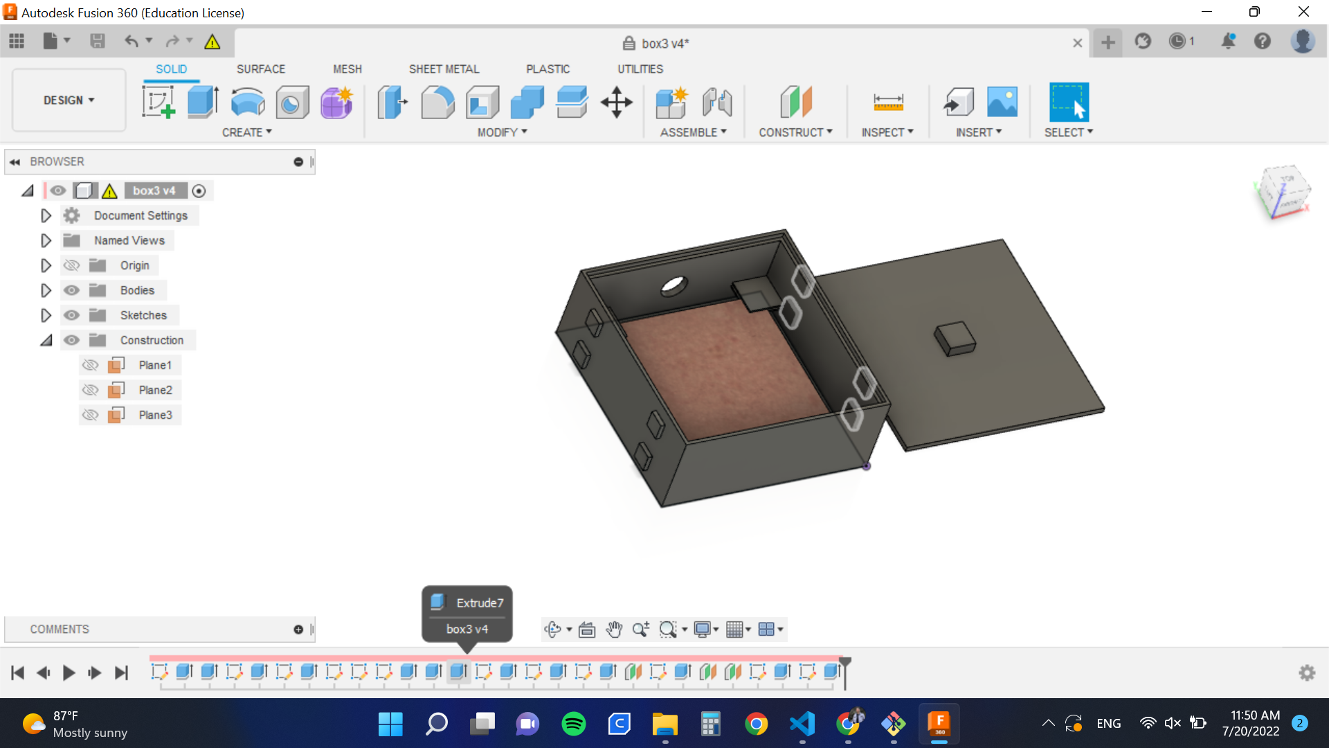
Upper Case Integration
- Upper Case: The upper case serves as a box containing the PCB and is meant for the integration of the project. It has a place for the PCB to sit and not move. This is done by having holders in the corners that fix the PCB from above and below.
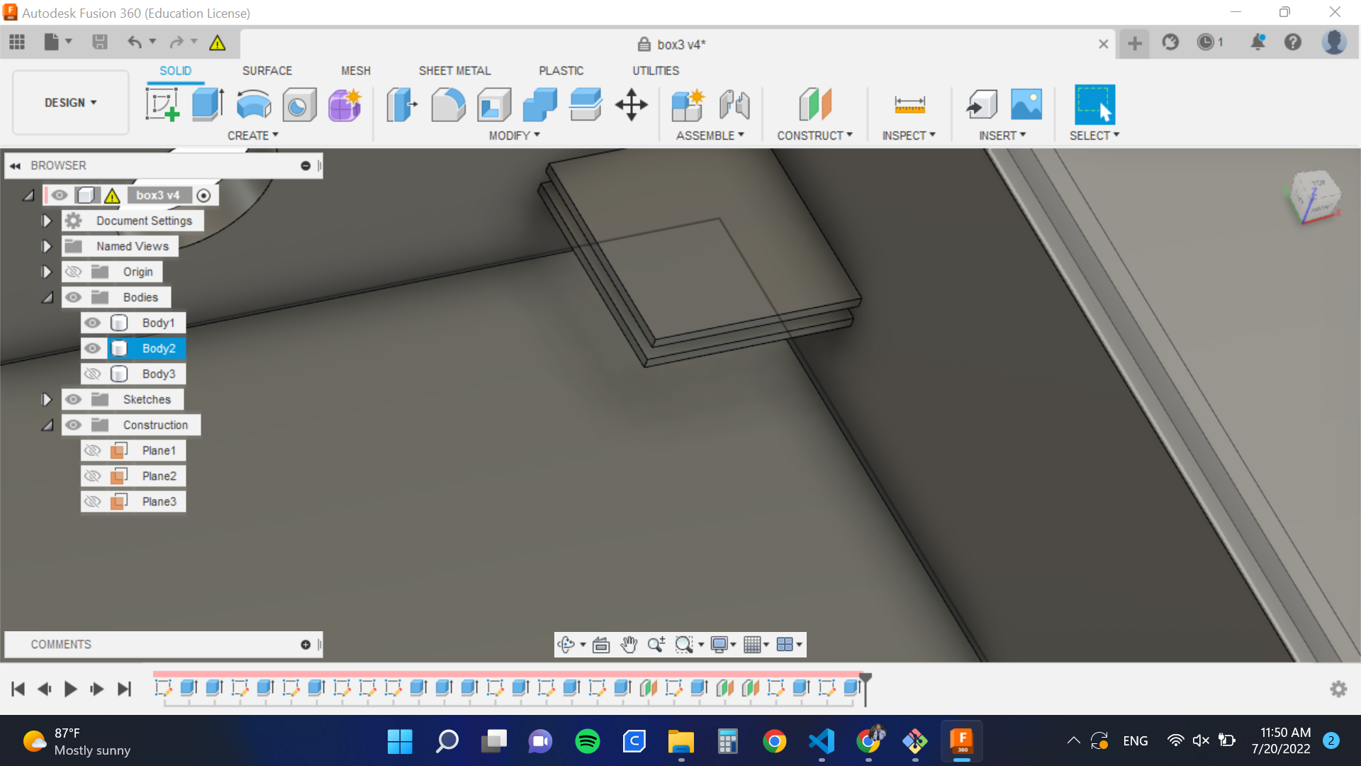
Also, I added a place from where the power cable can be inserted, as shown below:
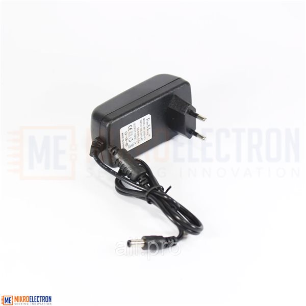
And this is the power cable (It will extend from a 12V adapter) I will use (Please note that the whole system will be powered using this adapted as indicated in the PCB design and production section below):
To download the file, press here
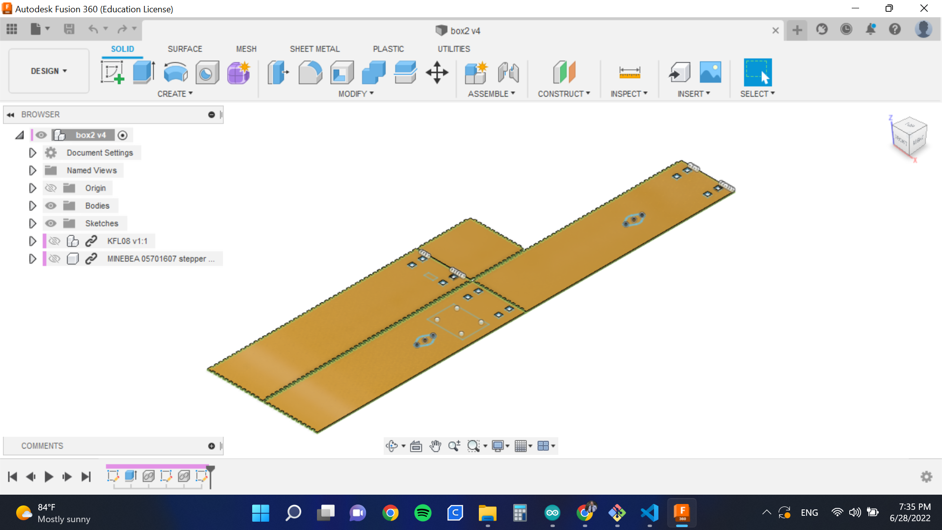
- Stepper Holder: The stepper holder is meant to fix the stepper to one wall of the outer case.
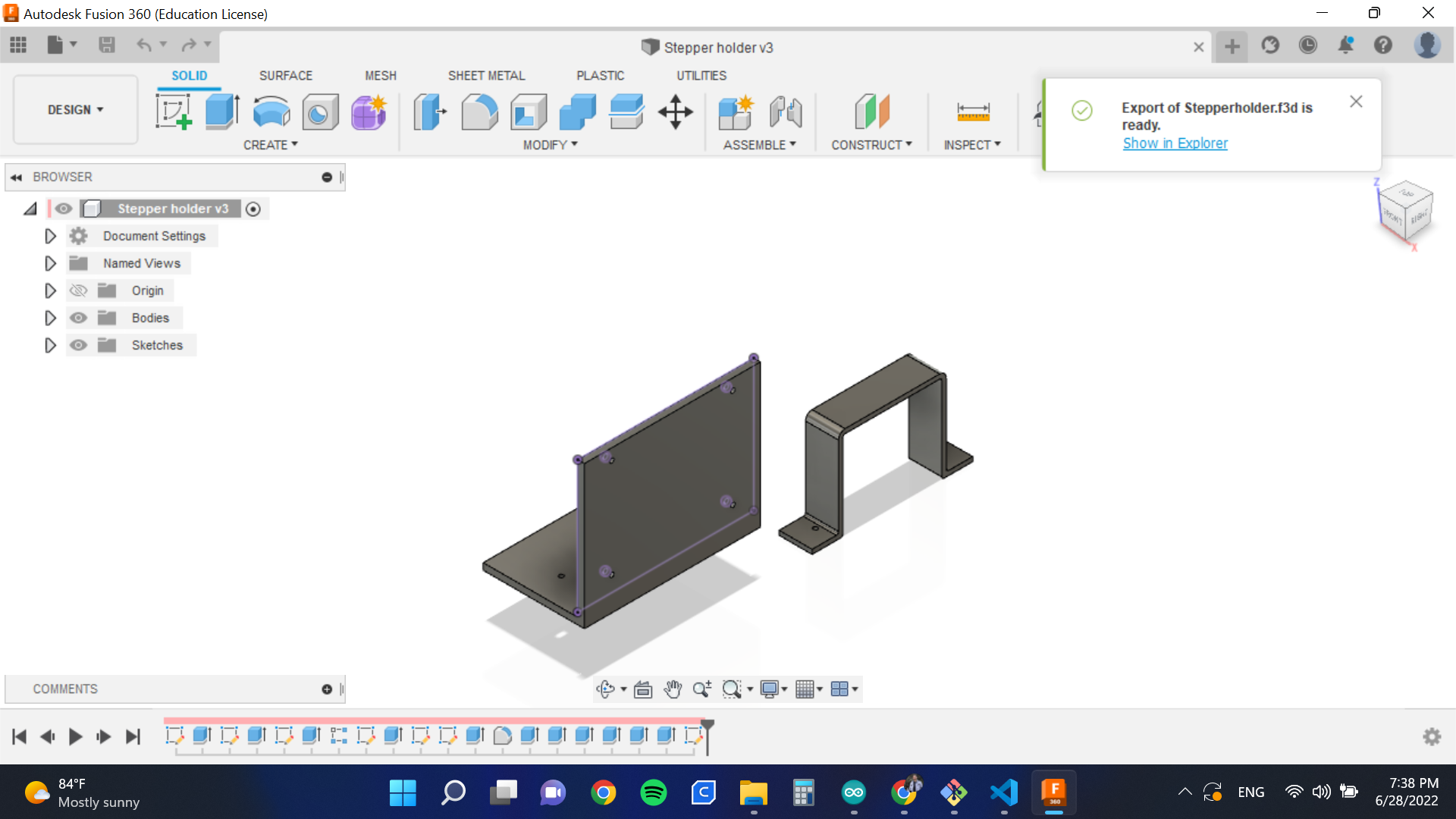
To download the file, press here
- Shaft: The shaft is meant to rotate, moved by the stepper. Its main task is to collect a string tied to the gripper holder.
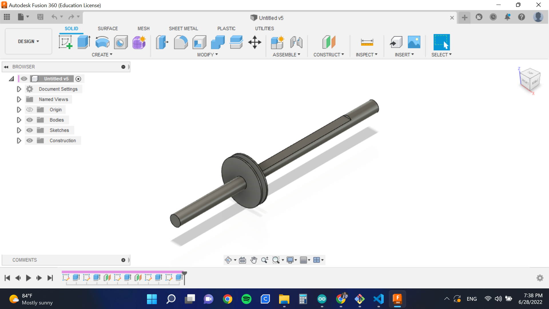
To download the file, press here
PCB Design and Production
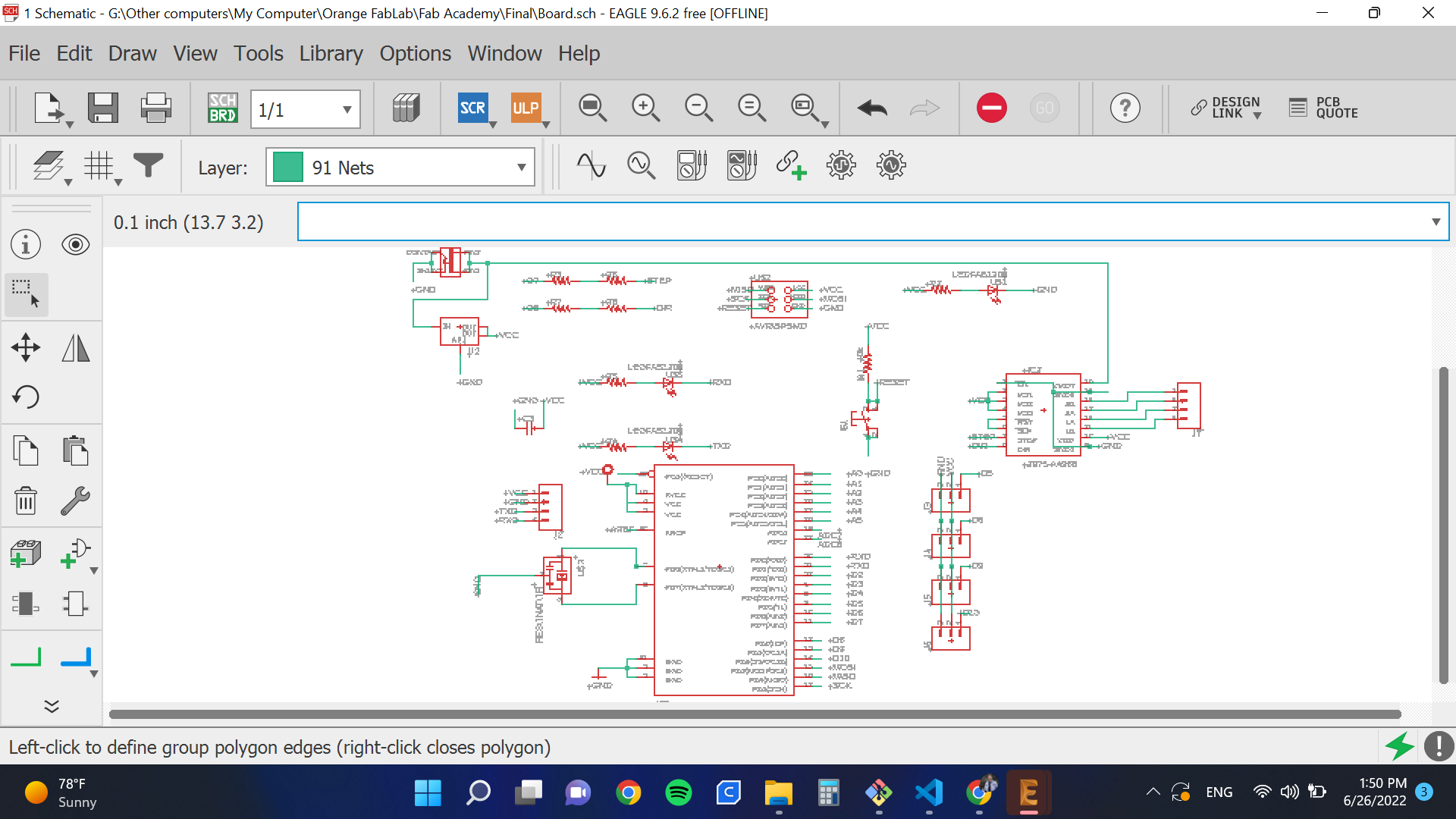
Schematic
I started with the schematic, where I connected all components. As I need a lot of pins, I used ATmega328P microcontroller. An advantage of this is being able to use Arduino libraries. It is worth noting that my friend Aybak helped me a lot in the schematic. He helped me understand multiple concepts including the need for a high resistor to connected with the reset.
Main Features
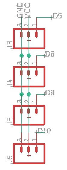
- To connect servos, I used a 3x1 pin header. 2 pins are connected to VCC and ground, respectively, while the third is connected to a signal.
- In order to work with a stepper I made place for its A4998 driver.
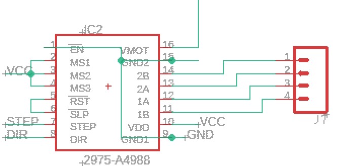
- When I tried to wire everything together, I had some difficult time connecting all signals. So, I used zero ohm resistors to fix the problem.

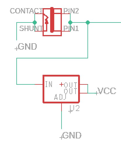
- The stepper motor requires 12V, but other motors and components cannot stand this high voltage. So I used a 12V power supply as the main source of power for the circuit and connected this to the stepper. But, I added a voltage regulator to power other components.
-
I added a place for a bluetooth chip to be connected.
-
The whole system will be powered via an external power supply, so there is a power jack that will have an adapted connected to.
The adapter:
Layout
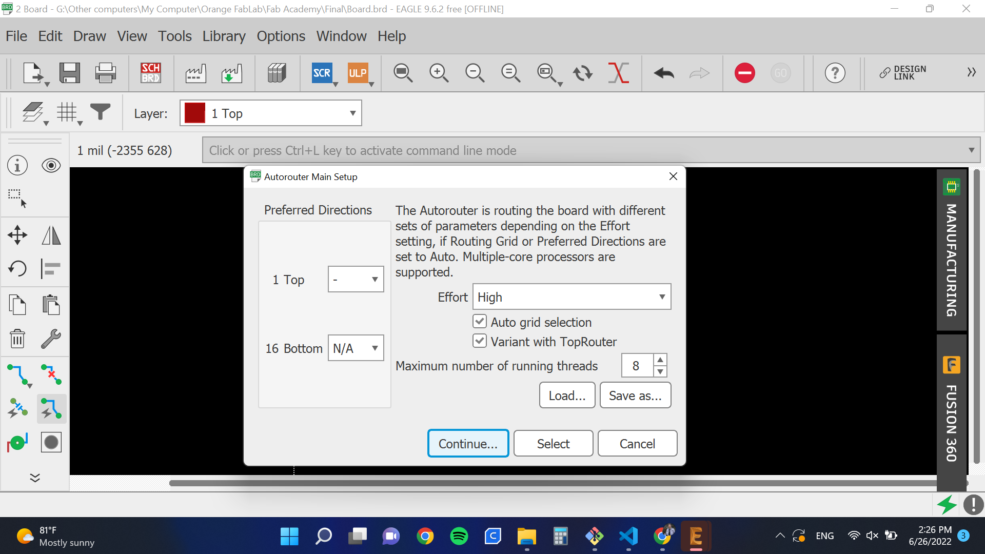
To connect signals, I used Autorouter. But it couldn’t connect everything so I used some zero ohm resistors.
I also edited the outer boundary to look as follows:
CAM
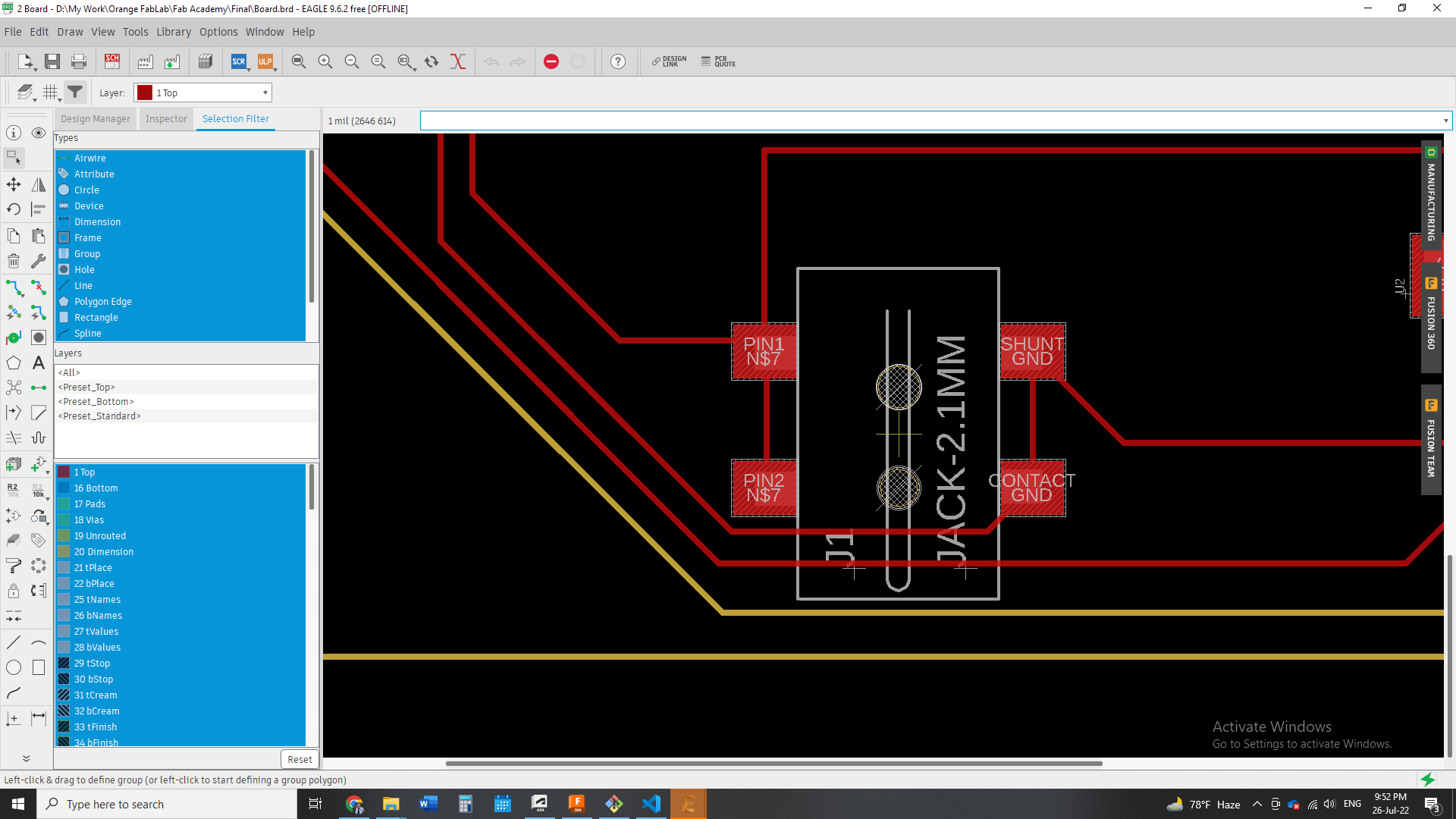
I exported the 2 images, one for the traces and one for the the outline as below. Also, note that I edited the inside colors for the outline picture because Fab Mods needs a difference in colors to detect where to cut.
Then, I transported this to Fab Mods to get the RML files.
Soldering
Then, I soldered the board.
Programming
I wanted to control all motors using serial communication and based on received data. So I uploaded the following code.
#include <Servo.h>
int x;
const int dirPin = 8;
const int stepPin = 7;
const int stepsPerRevolution = 200;

Servo myservo1;
Servo myservo2;
Servo myservo3;
Servo myservo4;

void setup() {
  myservo1.attach(5);
  myservo2.attach(6);
  myservo3.attach(9);
  myservo4.attach(10);


  pinMode(stepPin, OUTPUT);
  pinMode(dirPin, OUTPUT);
  Serial.begin(9600);
  Serial.setTimeout(1);
}

void loop() {
  while (!Serial.available());
  x = Serial.readString().toInt();
  if (x) {
    if (x == 1) {
      myservo1.write(0);
      myservo2.write(0);
      myservo3.write(0);
      myservo4.write(0);
    }
    if (x == 2) {
      myservo1.write(180);
      myservo2.write(180);
      myservo3.write(180);
      myservo4.write(180);
    }
    if (x == 3) {

        digitalWrite(dirPin, HIGH);
        // digitalWrite(dirPin, HIGH);
        digitalWrite(stepPin, HIGH);
        delayMicroseconds(1000);
        digitalWrite(stepPin, LOW);
        delayMicroseconds(100);
    }

    if (x == 4) {

        digitalWrite(dirPin, LOW);
        digitalWrite(stepPin, HIGH);
        delayMicroseconds(1000);
        digitalWrite(stepPin, LOW);
        delayMicroseconds(100);

    }


  }

}
HERO SHOTS
Servo
Stepper
AI Interface System
Computer Vision
I used Python to do pose estimation of my fingers. Mainly, I used CV Zone library, which is based on OpenCV and MediaPipe. I chose this library because it is high level and takes a few lines of code to build a very powerful deep computer vision model. Moreover, it is also connected to a serial communication library. So, CV Zone can do all the job alone.
My idea is basically to that the when a finger is up a signal is serially communicated to the microcontroller to actuate a servo. As the code below indicates, I started by importing the required libraries OpenCV and CV Zone.
import cv2
from cvzone.HandTrackingModule import HandDetector
from cvzone.SerialModule import SerialObject
Then, I created instances of the required objects: a camera, a detector, and a serial communicator. I also chose to have the maximum number of detected hands to be equal to 1.
cap = cv2.VideoCapture(0)
detector = HandDetector(maxHands = 1, detectionCon = 0.7)
Serial = SerialObject("COM4", 9600, 1)
After that, I started a while loop that reads the input frame from the camera, does pose estimation and finally checks if the index finger is up or down. If it is up, it serially communicates the number “1”. Otherwise, it communicates “0”.
while True:

    _, img = cap.read()
    img = detector.findHands(img)
    LandmarksList, BoundingBox = detector.findPosition(img)
    if LandmarksList:
        fingers = detector.fingersUp()
        if fingers[1] == 1:
            Serial.sendData([1])
        if fingers[1] == 0:
            Serial.sendData([0])

    cv2.imshow('Control Panel', img)
    cv2.waitKey(1)
Here is how the control panel looks:
Low-level Control
Now it is time to do the servo control code. I will use the same board I designed in “Output Devices”, whose microcontroller is ATmega328P. The code is as simple as shown below. What it does is basically reading serial data and actuating four servos based on it.
#include <Servo.h>
int x;

Servo myservo1;
Servo myservo2;
Servo myservo3;
Servo myservo4;

void setup() {
  myservo1.attach(5);
  myservo2.attach(6);
  myservo3.attach(9);
  myservo4.attach(10);
  Serial.begin(9600);
  Serial.setTimeout(1);
}

void loop() {
  while (!Serial.available());
  x = Serial.readString().toInt();
  if (x) {
    if (x == 0) {
      myservo1.write(0);
      myservo2.write(0);
      myservo3.write(0);
      myservo4.write(0);
    }
    if (x == 1) {
      myservo1.write(180);
      myservo2.write(180);
      myservo3.write(180);
      myservo4.write(180);
    }

}
HERO SHOT
Communication
For a start, “Bluetooth is a short-range wireless technology standard that is used for exchanging data between fixed and mobile devices over short distances using UHF radio waves in the ISM bands, from 2.402 GHz to 2.48 GHz, and building personal area networks.” Source
Bluetooth HC-05
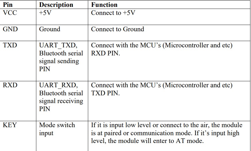
I will be using the HC-05 module, and in order to understand it fully, it is best to first refer to its manual.
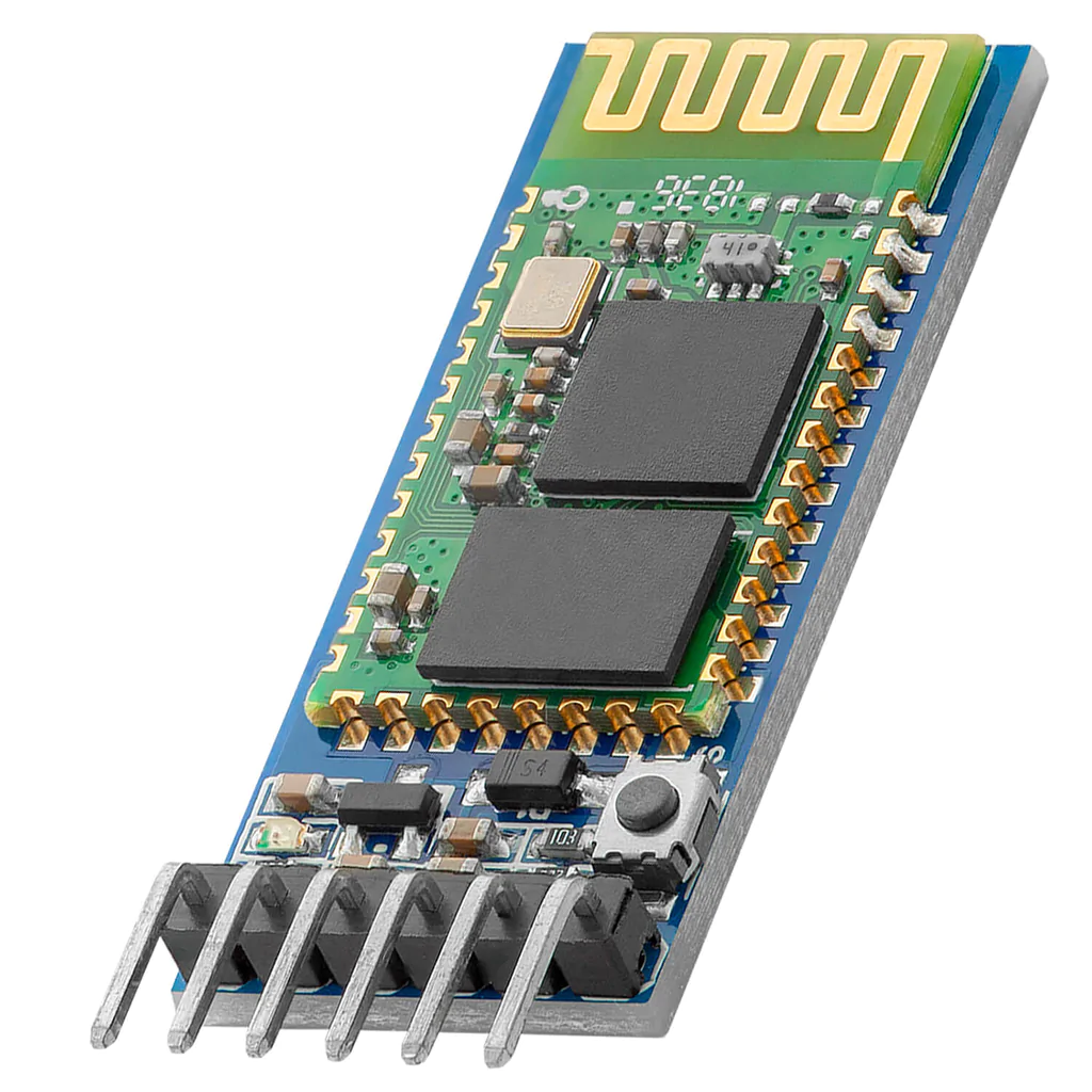
According to the manual, HC-05 has the following pins:
Essentially, to work with this module you need to at least connect 4 pins: GND, VCC, Tx, Rx. I already planned this in my Output Devices, as shown below:
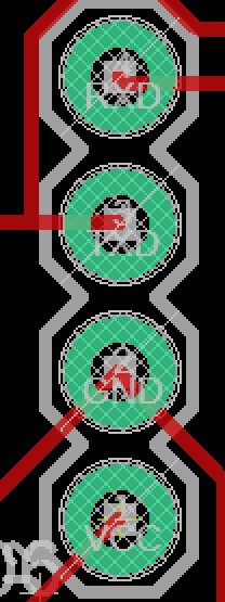
I also connected LEDs to Rx and Tx in order to know when any data is received or sent.
Code
So I basically linked this assignment with the Interface and application programming assignment. The idea is basically to use computer vision (programmed in Python) to do pose estimation of my fingers and then send serial data to the microcontroller, via Bluetooth, to actuate different motors.
So, I used the following Arduino Code:
#include <Servo.h>
int x;

Servo myservo1;
Servo myservo2;
Servo myservo3;
Servo myservo4;

void setup() {
  myservo1.attach(5);
  myservo2.attach(6);
  myservo3.attach(9);
  myservo4.attach(10);
  Serial.begin(9600);
  Serial.setTimeout(1);
}

void loop() {
  while (!Serial.available());
  x = Serial.readString().toInt();
  if (x) {
    if (x == 0) {
      myservo1.write(0);
      myservo2.write(0);
      myservo3.write(0);
      myservo4.write(0);
    }
    if (x == 1) {
      myservo1.write(180);
      myservo2.write(180);
      myservo3.write(180);
      myservo4.write(180);
    }

}
And for the Python code:
cap = cv2.VideoCapture(0)
detector = HandDetector(maxHands = 1, detectionCon = 0.7)
Serial = SerialObject("COM4", 9600, 1)
After that, I started a while loop that reads the input frame from the camera, does pose estimation and finally checks if the index finger is up or down. If it is up, it serially communicates the number “1”. Otherwise, it communicates “0”.
while True:

    _, img = cap.read()
    img = detector.findHands(img)
    LandmarksList, BoundingBox = detector.findPosition(img)
    if LandmarksList:
        fingers = detector.fingersUp()
        if fingers[1] == 1:
            Serial.sendData([1])
        if fingers[1] == 0:
            Serial.sendData([0])

    cv2.imshow('Control Panel', img)
    cv2.waitKey(1)
Here is how the control panel looks:
HERO Shot
I first tried controlling a servo:
Then, I tried controlling 4 servos, attached to the gripper I’m using in my final project.
Recommendations and Future Work
I plan to work on two parallel tracks in future.
First, I will develop the project to be 3-axis, and change the means of communication to 5G. Then, I will use it in our Orange 5G lab to showcase the benefits of using 5G and how data transmission (video stream) is seamless via 5G.
On the other hand, I will contact factories who work with soft materials, like eggs, and customize a gripper for their needs.