5. Electronics production
In this week, and for the first time, I got to experiment producing printed circuit boards.
Group Assignment
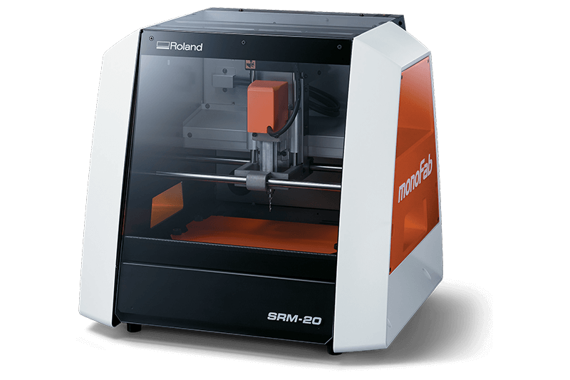
The milling machine we used this week is the Roland SRM-20. Below, I’ll take you through the process of making two line tests, one for traces and the other for outlines.
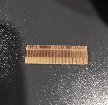
Traces
This test is important because it helps in choosing the appropriate milling parameters. In order to complete this task we used the below image, which we got from Lorena Delgado.
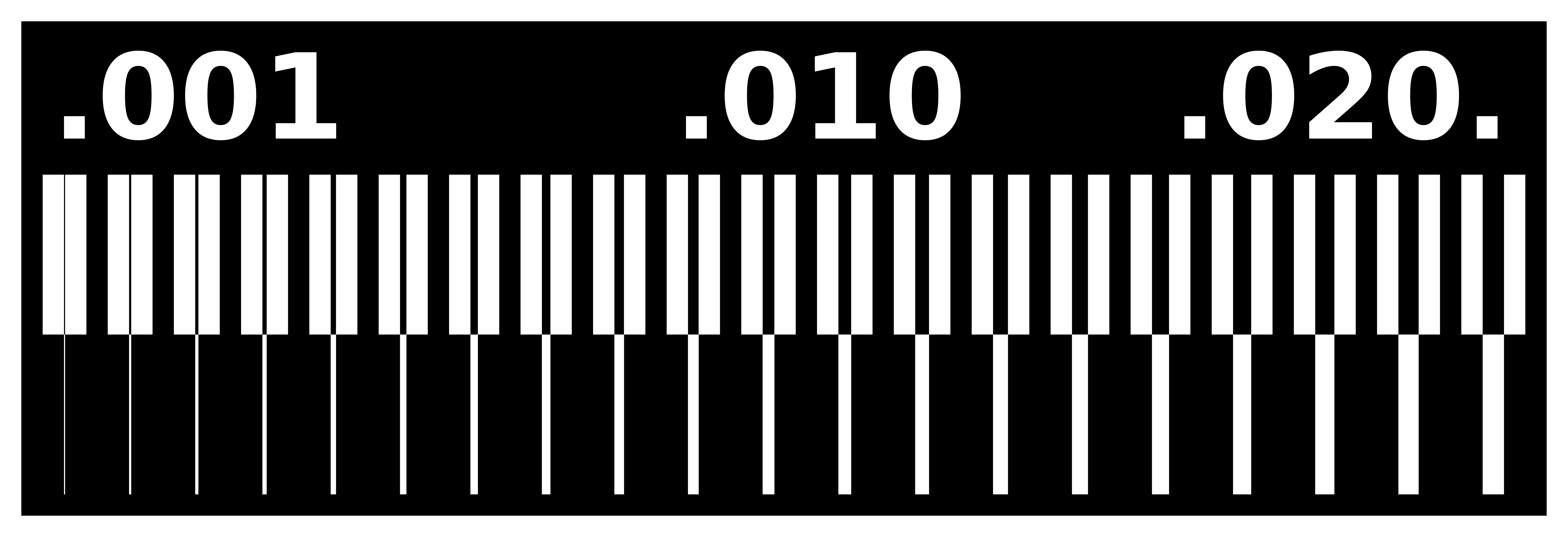
In order to prepare the file for milling, we used Fab Modules.
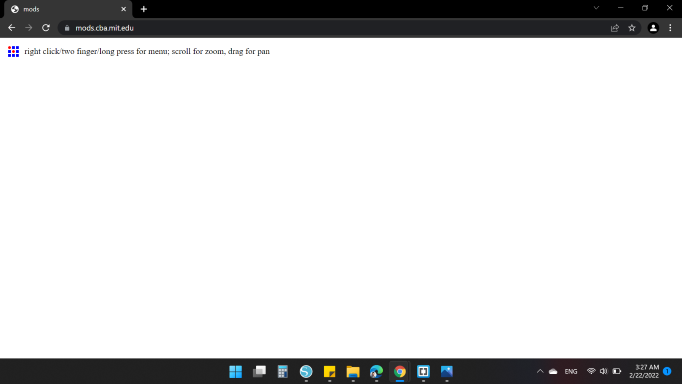
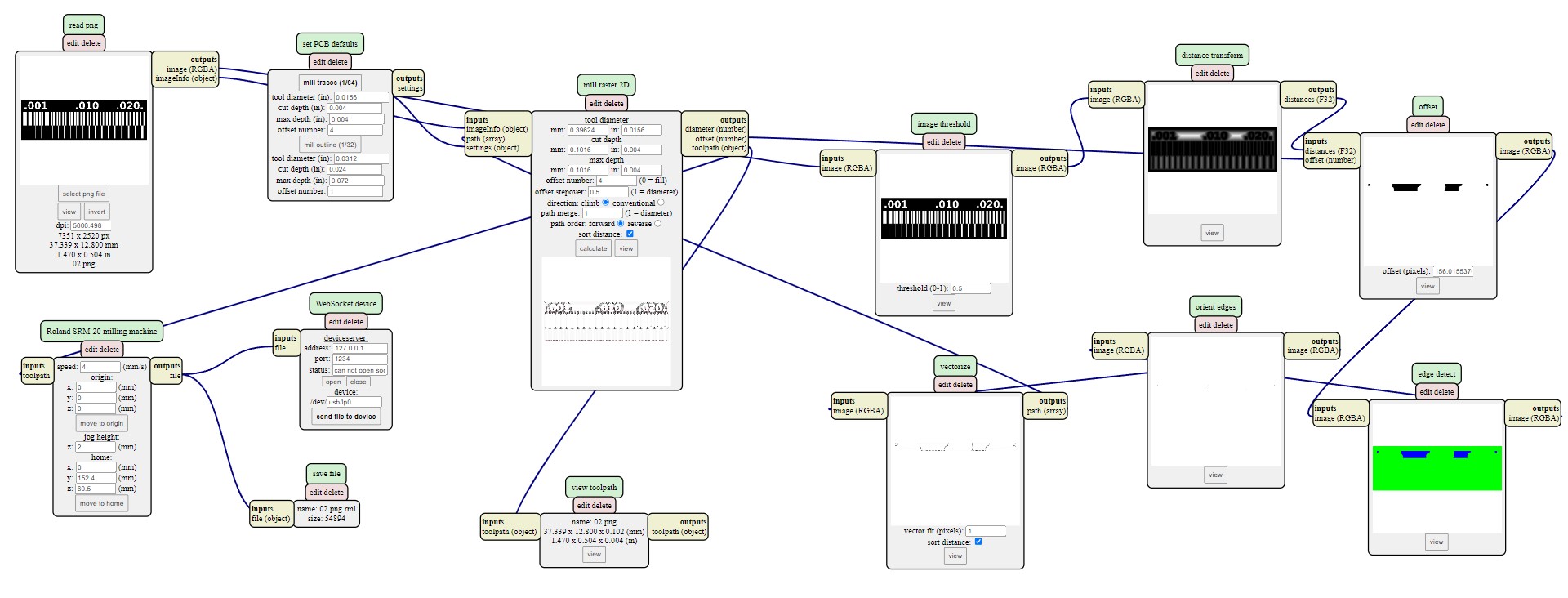
Then we did the following steps:
- We uploaded the png file.
- We chose the mill traces to be 1/64 inch.
- We set the tool diameter = 0.0156 inch, and the cut depth = max depth = 0.004 inch.
- We set the speed to be equal to 4 mm/s.
- We saved the file in rml format.
Outlines
For the outlines we followed almost the same steps, but we changed the mill tool to be 1/32 inch.
Operating the SRM-20
There are a couple of steps required for operating a PCB milling machine:
1. Fixing the FRM1 board to the plate using adhesive tape.
2. Adjusting the elevation of the end mill carefully.
3. Calibrating the (0,0,0) point. (I wonder why this isn’t automated yet.)
4. Uploading the file and starting the machine.

The final result looked as below
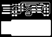
Individual Assignment
For the individual assignment, I decided to make am AVR Programmer. I found the following tutorial to be very useful! In the tutorial, I found the the traces and exterior images, shown below.
For the CAM process, I followed the same process aforementioned. So, I created the following (.rml) files:
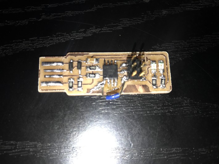
Soldering
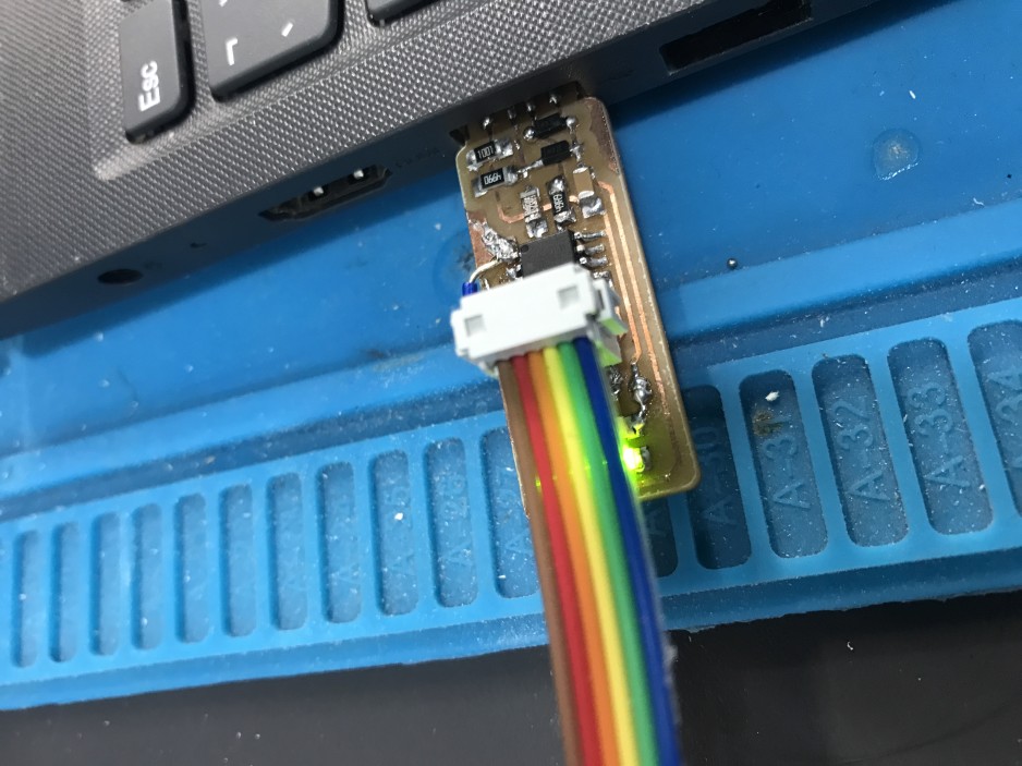
Now it is time to solder the components to the PCB! I’m kinda new to soldering, so you can imagine how frustrating this was. But, at the end I felt so satisfied to have my programmer ready!

And here is the final shot! While soldering, I faced a problem that one of the traces came out. So, I soldered a wire to connect the two ends.
Programming
I decided to use Ubuntu to program the ISP programmer. The following steps are followed to do so:
-
Download “Atmel AVR Toolchain for Windows” ZIP file. Then, extract it.
-
Edit the “make” file and specify the programmer’s name (I chose “usbtiny”)
-
Install the “avrdude”. Then, enter
sudo apt install avrdude gcc-avr avr-libc make
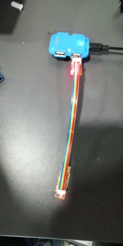
- Connect an old programmer to your programmer and make sure that you connect the pins the right way.
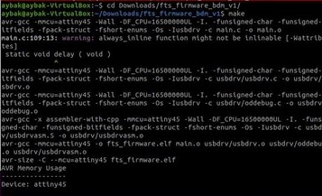
makeThis will build the hex file that will get programmed onto the ATtiny45. When the command completes, you should now have a file called fts_firmware.hex.butt before execute this command go to the fts_firmware_bdm_v1 file using cd command v
-
make flashThis will erase the target chip, and program its flash memory with the contents of the .hex file you built before -
make fusesThis will set up all of the fuses except the one that disables the reset pin

make rstdisblThis does the same thing as the make fuses command, but this time it’s going to include that reset disable bit as well.

HERO SHOT
To make sure my programmer is working, I used it to program an Arduino. I uploaded the blink code.